• Notice for iPhone users: DO NOT use the image size reduction option when uploading photos to the forum. This causes portrait images to post as landscape. We have added a warning to the image insert pop-up as well.

Help with Dual 70 Amp Relay Module

83CJ-8

Trying to catch up
Gold Member
Silver Member
City
Lewes
State
DE
I'm trying to explain this the best I can. I need your help identifying the screw terminals on the Leash Electronics Dual 70 Amp Relay Module, A+, A-, B-, B+. I've sent an email a week ago and have not received a reply, there's no phone number, customer service, or tech support. How are these screw terminals labeled in relation to pins 85 and 86 on the relays?
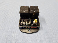
20240119_090312.jpg
I want to wire to a Dakota Digital Electronic Fan Controller PAC-2800BT using this YT video
(starting on the video at 4:52 min.) They have terminal 86 from both relays spliced together and powered by a 12-volt constant. Terminals 85 from the relays connect to the Fan High and Fan Low on the controller.
 
Last edited:
On a standard relay #85 is the coil voltage negative terminal, #86 is coil voltage positive terminal.

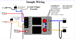
On the Leash dual relay you have the terminals from left(blue) to right(red) would be 86, 85 for left relay coil and 85,86 for right relay coil.
The Batt + would be your power source that supplies both relay common contacts and the outputs would be the the corresponding outputs controlled by the respective relays.

This is a diagram that may help. The "C's" identify the polarity of the relay coils.

relay.png
 
On the Leash dual relay you have the terminals from left(blue) to right(red) would be 86, 85 for left relay coil and 85,86 for right relay coil.
Got it "Thank You" That's how I had it drawn from the beginning, A+=86, A-=85, B-=85, B+=86
I printed out that sample diagram but It was the ground from the C- terminal that had me second-guessing myself.

A+ & B+ terminals are connected to a single wire of 12volt constant to supply power to the relays and A- & B- out to Fan High and Fan Low. Another thing is, that I've never dealt with relays where the terminals were labeled A B, or C.

Edit: I corrected my typo.
 
Last edited:
Got it "Thank You" That's how I had it drawn from the beginning, A+=86, A-=85, B-=85, B+=85
I printed out that sample diagram but It was the ground from the C- terminal that had me second-guessing myself.

A+ & B+ terminals are connected to a single wire of 12volt constant to supply power to the relays and A- & B- out to Fan High and Fan Low. Another thing is, that I've never dealt with relays where the terminals were labeled A B, or C.
Sent you a PM
 
Back
Top