• Notice for iPhone users: DO NOT use the image size reduction option when uploading photos to the forum. This causes portrait images to post as landscape. We have added a warning to the image insert pop-up as well.

Cleaning up Wiring After Nutter Bypass- trivia/ help needed

joshvt

Scrambler Enthusiast
Lifetime Member
City
charlotte
State
nc
I finally got around to doing the nutter bypass. I now have MC2100 and all unnecessary vaccum lines, etc. removed. I am now working on cleaning up and removing the wiring associated with the computer. Working backwards from the computer plug and diagnostic plugs, I have been tracing and then removing each wire. I am down to the last few and unsure what to do about the remaining wires. Hoping someone can answer these questions:

1. What is the white relay located on the passenger side? it has a white and black wire that splits and goes to the computer and the diagnostic plug. It also has a red wire that goes to the 6 pin connector. And it has a pink wire goes to the small plastic fuse box looking thing. What is this relay for and can I delete it? Picture attached.
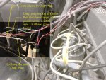
Relay Wires.jpg

2. There is another white relay towards the center of the firewall. I believe it controls the manifold heater and electric choke. I intend to leave this in place. The choke has a second wire coming out of it that goes to the diagnostic plug. can I simply cut the wire to the diagnostic plug off at the choke? Picture attached.
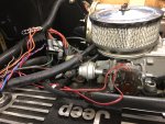
Choke Wires.jpg

3. There is green wire that runs from the ignition box (same plug as the orange and purple wires used for the nutter) to the diagnostic plug. This a white wire branches off before the diagnostic plug and goes to the plug at the coil. When I unplug this wire at the coil, the engine will not start. It starts fine when the coil plug is plugged in. I am assuming I can remove the section of wire to the diagnostic plug and make a clean spice from green to white?
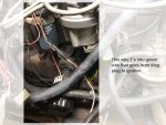
Coil Wire.jpg

4. Should the 6 pin connector remain? The manifold heater/ choke relay appears to be powered from this, but it looks like the other pins can be removed?

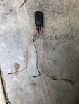
5. Can the black fuse box looking thing be removed/ what does it do? It clipped one wire that traced to the computer. the remaining wires go to the 6 pin connector and the relay mentioned above. Picture attached
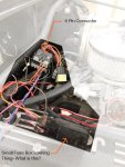
6 pin connector.jpg

I appreciate any help.
 
What year Jeep is this?

IIRC, there is a red wire from the choke circuit that runs back to the diagnostic plug. It's only function was so that you could check for voltage at the choke at the diagnostic port.

There are quite a few other circuits that do the same thing, i.e. they have a wire that runs back to the diagnostic port for the sole purpose of checking for voltage of that circuit at the diagnostic port.

I did the opposite of you, one time, tracing out all the wires when I swapped in a BBD Feedback harness from a 1984 into my 1983. IIRC, there was only one wire color difference.

Not sure on that black fuse looking thing, I have not ran across one of those yet.

Not sure on the white relay on the passenger side.

The relay on the DS does feed that intake heater and a few other things. IIRC, it gets power from the 6 pin connector. There are a few wires that can be removed from the 6 pin connector, looks like you did already.

On that ignition wire, you should be able to spice it like you mentioned.
 
Thanks for responding- Understanding electrical systems is not my strenghth so this is helpful. My scrambler is a n '85

You confirmed a few of my assumptions (choke wire, ignition wire splice and manifold heater relay).

After searching many forums, I think the other relay is for the idle/ sol vac which as far as I understand served to maintain a constant idle when varying loads kicked in at idle (a/c, etc.). I have removed the sol vac device so I am thinking I can remove this relay as well- it has wires going to the 6 pin connector and the black box. Planning to remove one wire at a time making sure the jeep starts and everything works after each snip.

I haven't yet found an explanation for the back fuse box looking thing, although I have found a few people saying the backup lights were somehow wired through the computer harness and I am wondering if this has something to do with the backup lights.

I should have some time to mess with it this weekend and hopefully figure the rest of this out and get the wiring removal wrapped up.
 
Thanks for responding- Understanding electrical systems is not my strenghth so this is helpful. My scrambler is a n '85

You confirmed a few of my assumptions (choke wire, ignition wire splice and manifold heater relay).

After searching many forums, I think the other relay is for the idle/ sol vac which as far as I understand served to maintain a constant idle when varying loads kicked in at idle (a/c, etc.). I have removed the sol vac device so I am thinking I can remove this relay as well- it has wires going to the 6 pin connector and the black box. Planning to remove one wire at a time making sure the jeep starts and everything works after each snip.

I haven't yet found an explanation for the back fuse box looking thing, although I have found a few people saying the backup lights were somehow wired through the computer harness and I am wondering if this has something to do with the backup lights.

I should have some time to mess with it this weekend and hopefully figure the rest of this out and get the wiring removal wrapped up.
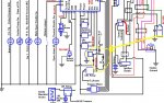
Here's a wiring diagram for the computer that should help with tracing some of the items:
http://home.sprynet.com/~dale02/wire-sml.htm

If you scroll down to "Table of Contents" you can learn more than you ever wanted to know about the emission system.

Never heard the B/U light - computer harness wiring. Off to look at my wiring diagram.
 
Thanks. I have been through the “adventures under the hood” website in detail- it’s interesting. Have looked at the wiring diagram before attempting to figure some of this stuff out. I don’t see the mystery black fuse box looking thing or the 6 pin connector?
 
Thanks. I have been through the “adventures under the hood” website in detail- it’s interesting. Have looked at the wiring diagram before attempting to figure some of this stuff out. I don’t see the mystery black fuse box looking thing or the 6 pin connector?
It's hard to tell from your pic which color wires go where in relation to the black box.
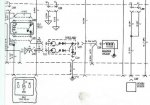
I believe the black box is the diode assembly for the computer controlled emission system.

Anyway, the attachments are from the diagram from the link, and a part of my '83 owners manual.
You should be able to trace from the diode assembly out to the other components.
The colors may not be the same for yours but the wiring should be similar.diode.JPGdiode schematic.JPG
 
Black box and idle relay eliminated. Coil wire branch to diagnostics plug eliminated as well. Jeep starts and everything works. Woohoo. The diode assembly (pic attached) connected to the idle relay, the 6 pin connector and a couple other wires that i cut earlier on. More wires than were are shown on the diagram. Tomorrow I will clean up the firewall, and get everything back in the loom and tidied up- glad to be done with this. Thanks for the help
0F53CCA7-DB0D-4D8D-9B88-982E766B8BAF.jpeg
 
Back
Top