• Notice for iPhone users: DO NOT use the image size reduction option when uploading photos to the forum. This causes portrait images to post as landscape. We have added a warning to the image insert pop-up as well.

Chevy 5.3 wiring

Ron84cj

Engine nerd
Lifetime Member
City
West Bend
State
WI
So I have been modifying my harness and for the most part I have most of it done. I got rid of all the unnecessary items like egr, rear 02 sensors, auto trans stuff etc. I am now to the point where I can wire in my fuses and relays. I have been doing a ton of reading on this whole wiring project and I can't really find which which wires I can all splice in together and what size fuses I need. I'm assuming all of the injectors can go to one. Does the pcm have to be on its own or can I run the maf and 02 sensors to the same one? I want to simplify this as much as possible and from what I've seen elsewhere people only run like 4 to 6 fuses. I hope this makes sense. I really struggle with wiring.
 
It's WAY easier to just buy a new harness that uses NEW wire which will also allow you to mount the ECU inside the Jeep...
 
It's way easier and way more expensive. My harness was in great shape and I already went through it. It's not terribly hard just really time consuming. I just need to figure out my fuse block situation. I know the orange wire is constant and the pink wires are keyed. Here is my list. Do I need to run them separately or can I group some together? And if so, which ones and what size fuses?
Pin. Color.
B8. Orn. Pcm
C4. Pnk. Maf
C10. Pnk. Inj 1,3
C11. Pnk. Pcm
C12. Pnk. Inj 2,4
D8. Pnk. 02 sensors
D10. Pnk. Inj 5,7
E6. Pnk. Coils 2,4,6,8
E7. Pnk. Inj 6,8
E12. Pnk. Coils 1,3,5,7
F2. Pnk. Pcm
 
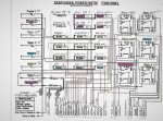
Here's what I ended up with. Hope you can read this. I modified a Delphi First responder panel to cover not only the engine but all the electrical.

wiring scan (2).jpg

Basically split the injectors/coils into 2 fuses, left bank/right bank, then ECM B+, ECM IGN, TAC, O2's, and so on. I had a lot of available fuses so I split it up as much as I could- I figured that way diagnosis would be easier should the need arise. I also use the ignition switch as primarily a power switch for relays. All relays are fused before the relay and provide power to the starter, fuel pump, and lockers. Others provide power top a bank of fuses, while battery constant passes through a maxi-fuse on to sets of mini fuses. So everything is pretty much double fused. The only high-amp item that runs through the ignition switch is the aftermarket HVAC blower. I also rely heavily on LED lighting for everything but the headlamps. That being said, I have installed several other harnesses in street rods that have been terminated with around 3 fuses and 1 relay for the fuel pump. I guess it depends on how you prefer it. With more fuses, a blown fuse pretty much leads you to the problem. With fewer fuses, a blown fuse means you lose everything and have to start diagnosis from there.
 
Last edited:
That's what I am after, but I can't hardly read it. Would you be willing to scan it for me and email me? Sorry, I'm really not trying to be a pain. I really appreciate the help.
 
I scanned it, tweaked the clarity as much as I could. I figured there might be others that would want to see. If you want me to EMail, just PM your info.

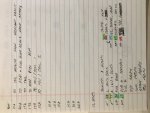
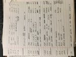
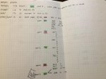
Here's some of my chicken-scratch notes for circuit design...

IMG_5404.jpg

IMG_5405.jpg

IMG_5407.jpg
 
Last edited:
The ones I've done are very similar to Randy's

The one I'm doing right now I broke everything up the same as it was in the truck. It was a lot of research through the schematics, but now I con use them for troubleshooting later if needed. I just wrote the new relay and fuse numbers on the prints.
 
Back
Top