• Notice for iPhone users: DO NOT use the image size reduction option when uploading photos to the forum. This causes portrait images to post as landscape. We have added a warning to the image insert pop-up as well.

Retitled: 83 Scrambler resto-mod finally gaining momentum

God I hope I get sent to the springs next duty station. Germany is interesting but not where I want to be in life right now. Besides... I'm sure you need another Scrambler to park next to. :)
 
God I hope I get sent to the springs next duty station. Germany is interesting but not where I want to be in life right now. Besides... I'm sure you need another Scrambler to park next to. :)

take advantage of your time in Germany... I've been trying to get there (unsuccessfully) for 20 years, and have only managed on TDY trip. It's only going to get harder to get there (my brothers were all stationed in Germany on their first tour in the Army, back when there were 2 Corps HQ and ten (!) Army divisions there, now we're hanging on to a few Brigades). You've got forever to work on Jeeps/cars... living in Europe on the Army's dime is a rare chance to see the world.

I love CO and would retire here (if I can find work when the time comes), but I'd still like to get a EUCOM/AFRICOM tour in before I hang it up. There's nothing particularly special about Ft Carson (other than the view), but living in CO is great.
 
Finally getting around to working on my wiring harness merge.. the Scrambler has been doing nothing for a year but collecting dust and flat-spotting tires while I moved, worked, bought a house, sold a house, started on an MBA prorgam at night school... excuses excuses. Now I'm (again) under some time pressure to get it working... and trust me, after trying to figure out corporate bond coupon rates and yield-to-markets.. the wiring swap is a welcome/alternate challenge.

So.. I'm standing by on a fellow forum member to email me the factory wiring diagram for the 94 YJ that I used as a donor. In the meantime I re-read all the collected web-pages and notes I have stored over the last few nights to get re-freshed on "five wires to fire" and, away we go...

As a start point: I installed a Painless harness on my 8 about 6-7 years ago and, as it has never been road-worthy since then, the wiring harness is still clean and labeled but... not necessarily the same as the original CJ harness so, a FSM does me little good on the CJ side.

I have questions.. please read on...
 
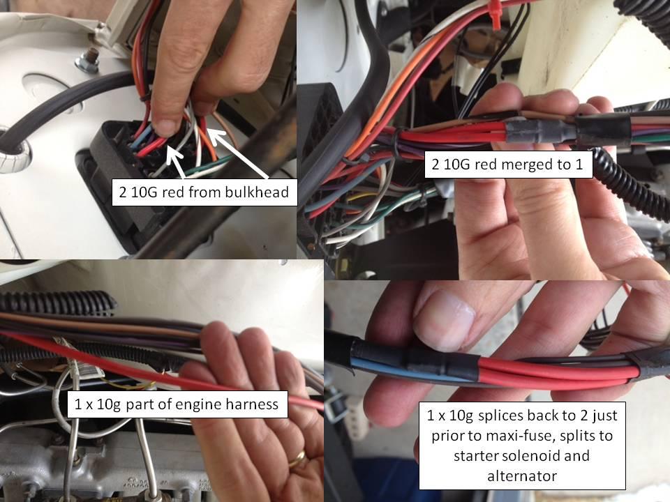
As I'm waiting on the YJ FSM references, I started by taking the counduit off the CJ/Painless harness and identifying which wires I think I need. First up, and most obvious: the main power (10G Red) to the CJ bulkhead:

cj10gredengineharnessrouting_zpsbd11b78f-1.jpg


as you can see, the Painless harness has 2 10G red wires coming out of the bulkhead. They quickly merge into one, and are later spliced back into two on the PS of the engine bay.. one goes to the (now missing) CJ starter solenoid, the other to the alternator, and there was a maxi-fuse in-line there somewhere. I think that I'm cutting this single 10G just outside of the CJ bulkhead and splicing the YJ 10G red wire from the "fuseblock" fuse at the YJ PDC (pics follow).

XXXX EDITED POST XXXX
I'd previously posted a photo of the WRONG lead from the PDC to the YJ bulkhead connector. I"ve since discovered the correct YJ power source and will document in a new post.
 
Last edited:
Is this the same as "crank"?

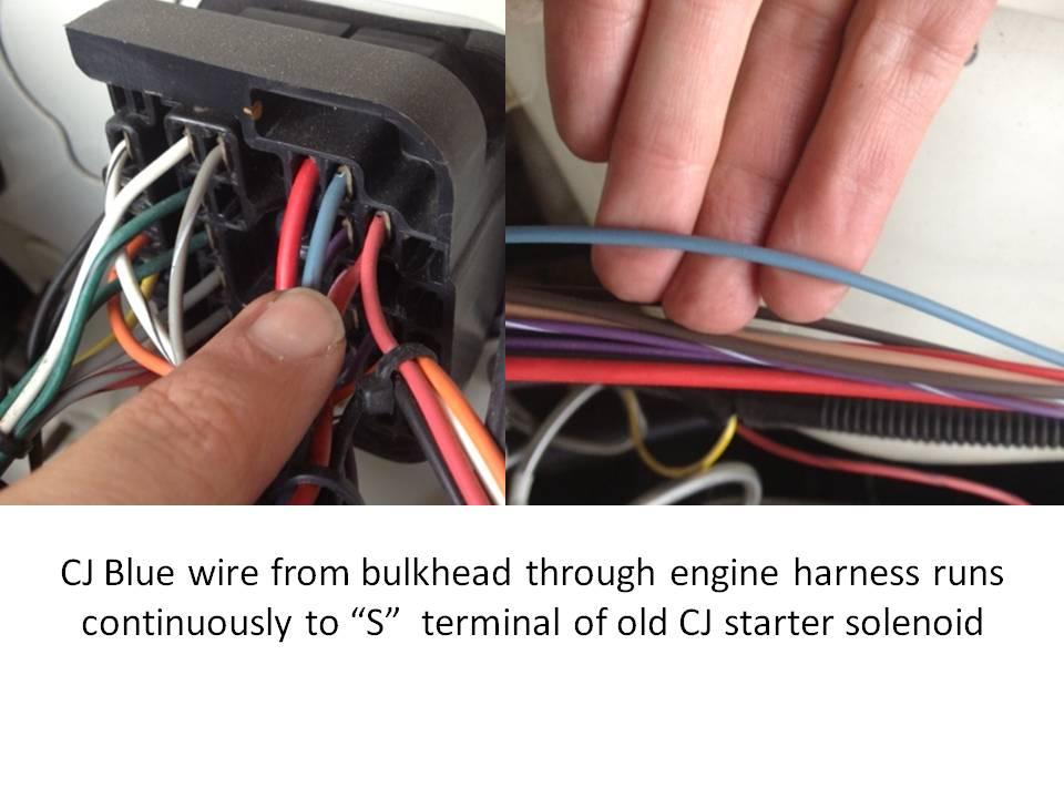
For the next "wire to fire", I have the CJ blue 16G out of the bulkhead which eventually ran to the "S" terminal of the old CJ starter solenoid.

CJBlueSwire_zps34425002-1.jpg


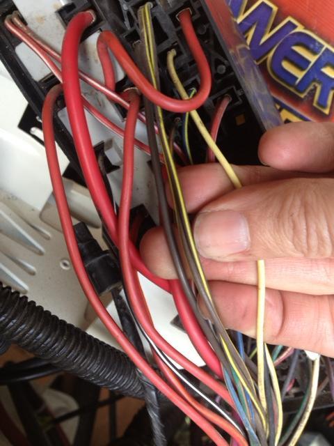
I think this is getting spliced to one of the wires from the YJ PDC "starter" relay. If I'm reading the relay right, the power IN ot the relay (signal in) is the yellow 18G to post #85. There are two grey/yellow 18G running into post #86 of the relay, and the grey 16G wire out of the relay at post #87 runs directly to the starter.

I'm holding the four wires in this pic: single yellow, double gray/yellow, single gray to starter.
yjstarterrelay_zps53bcf632-1.jpg
 
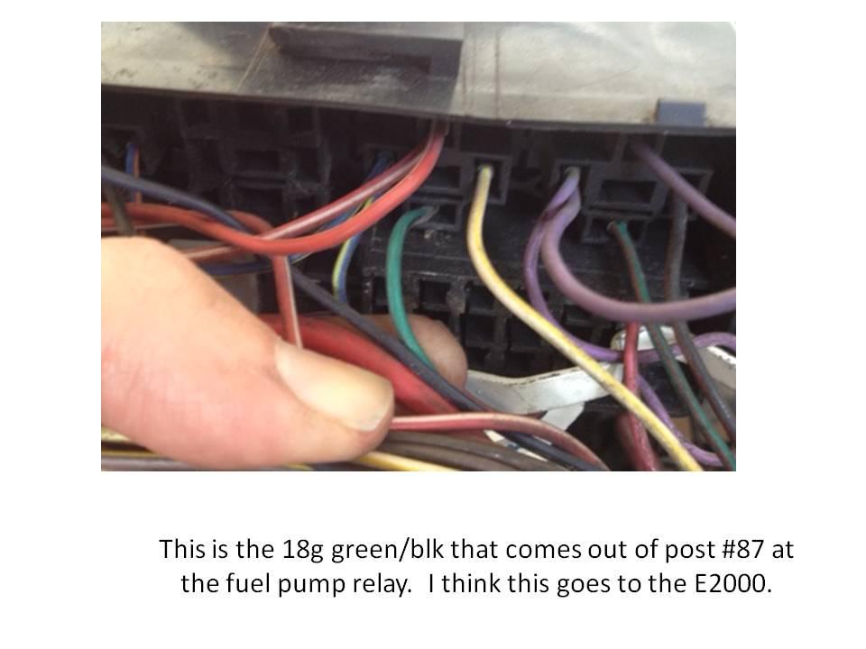
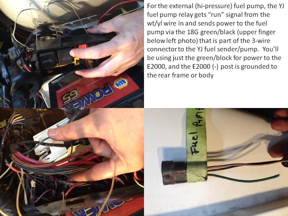
Fuel pump: I think I'm running this green/black 18G from the PDC "fuel pump" relay back to the E2000 + terminal.
It's the wire at the center of the pic, in front of my index finger:

yjfuelpumprelaytoE2000_zpsdb037596-1.jpg
 
XXX EDITED POST AS OF 2/24 WITH SOME INFO UPDATES XXXX:

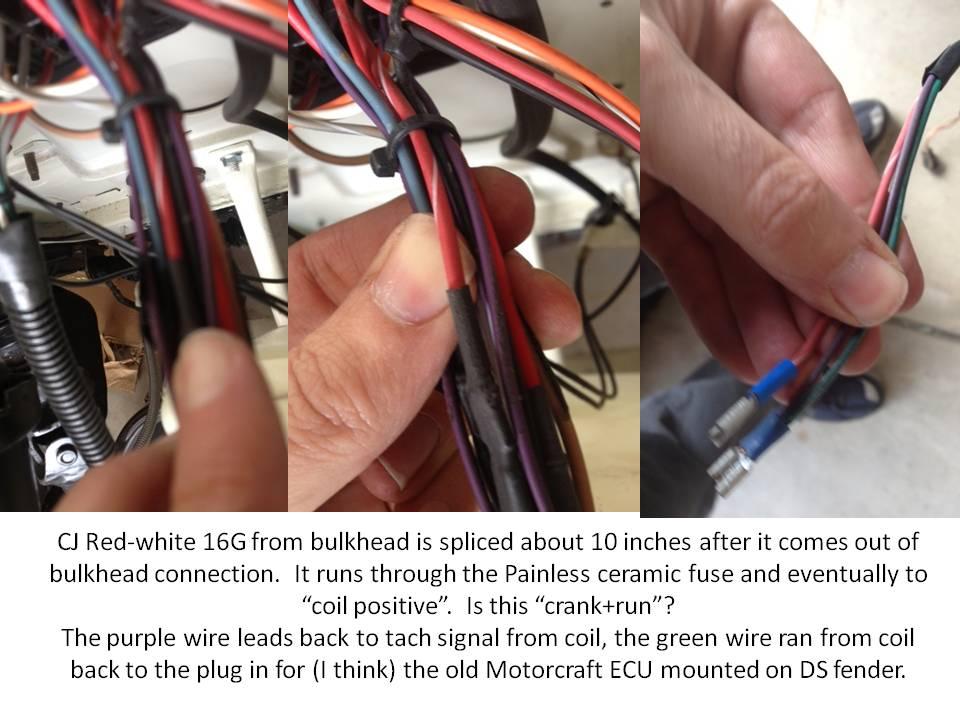
This red/white is "crank/run" from the CJ bulkhead.

The red/white 16G out of the CJ bulk head used to run to the positive side of the CJ coil.

cjrewhitetocoilpositive_zps6ce6a77c-1.jpg


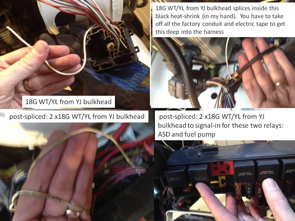
This CJ red/white wire will splice with the 18G wt/yl from the YJ bulkhead. This single wt/yl will eventually splice: one goes signal in to the fuel pump relay, one goes to the automatic shut-down relay, both of which are in the PDC. Pics to follow.
 
Last edited:
Updated as of 24 Feb, the "five wires" solution is:

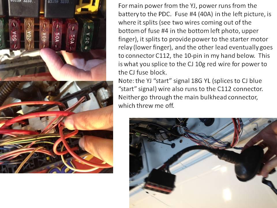
1. Main power (10G red at CJ bulkhead to "fuseblock power" red10G from YJ PDC (terminates at connector C112, which is a medium sized connector that mounts in the driver's footwell, pics follow).
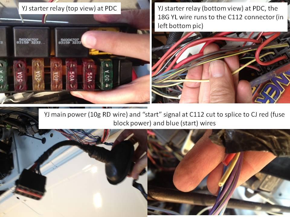
2. Ingition/crank (16G blue wire at CJ bulkhead to starter relay on PDC for YJ harness, 18G yellow, which also terminates at connector C112, pics follow)
3. Ignition/run (16G red/white from CJ bulkhead to unknown wire from YJ harness, connects to the single 18G WT/YL from the YJ bulkhead connector which later splices into at least two leads: one goes to the Auto-shutdown signal in, the other goes to the fuel pump relay signal in)
4. Fuel pump relay (18G green/blck from YJ PDC to + side of E2000)
5. The fifth is... neutral safety? My donor was a YJ auto with the TF trans so I need to figure out the grounding (or possible switching) required to allow it to run.

Others I still need to figure out: VSS (I have the HESCO adapter on the front dampener).
 
Last edited:
Looking good!
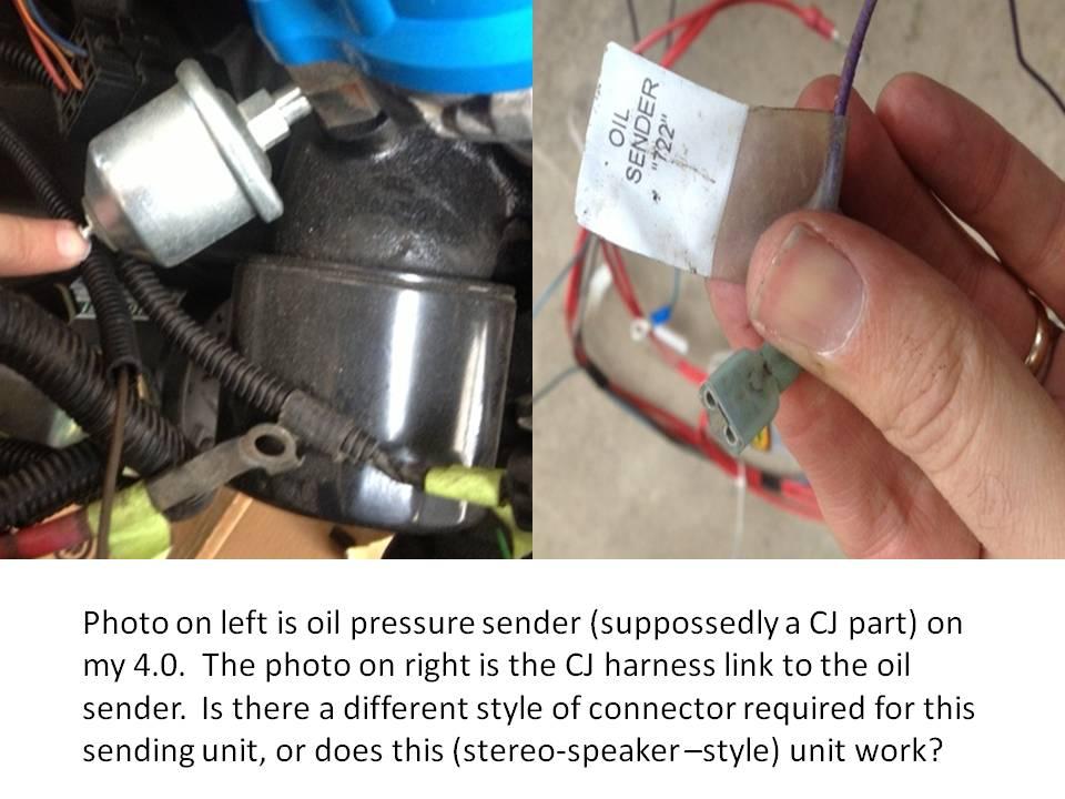
Oil pressure connector should slide straight on that switch, but will never fit super tight and can rotate for some reason. So i would copper slip(hope its called that in the states!) it to make sure it cant get moisture behind it.

As for Item 5 above it may be different on yours but on my TF the neutral safety switch is connected to the ground on the starter solenoid and if you have to buy one (which i did) its a different part number and starter solenoid to the manual gear boxed Jeeps.

So on the auto the ground runs up from the safety switch to a ground connector on the starter solenoid and on mine that ground connector on the starter solenoid is isolated from the frame to allow it to work only in park and neutral .:crazy:
 
This type connector would work better and you maybe able to find at a local auto store to save shipping. When I removed the unused wiring from the CJ engine harness there was a double one of that type and it fit my jeepster brake switch perfect. It had the female spade type on it before and was not a good connection. You may be able to use that if you have it.

http://www.repairconnector.com/products/GM-Single-Wire-Coolant-Temperature-Sender-Connector.html
http://www.americanautowire.com/shop/connector-housing-temperature-sender-con
http://www.ebay.com/itm/PICO-WIRING...CI%2BUA%2BFICS&otn=21&pmod=400338009077&ps=54
http://www.summitracing.com/parts/pco-5665pt/overview/

I swapped a CJ oil pressure sender onto the YJ block. See question below:

CJOILPRESSURESENDERWIRE_zpsc9487851-1.jpg
 
Others I still need to figure out: VSS (I have the HESCO adapter on the front dampener).

The VSS is mounted to your transfer and the CPS is on the damper, you may need to lenghten the cps wire.
The VSS, You need to get one with the electrical and mechanical hook up if you plan on using the CJ speedo. One from a 91 YJ will work, and from a late 80's Dodge Dakota.
I used the late model dodge dakota as it was the cheapest.

Found a little more notes for you that might help you see below for fuel pump in 4th comment and #4 comment

1st, Label all the engine related connectors, including the VSS.
2nd, Remove all the flex-loom and electrical tape. A large portion of the harness will simply "fall out" as the headlight, horn, heater and all non-engine related wiring shares the flex-loom but is not integrated into the F.I. portion.
2nd, Some non-engine related systems are hard wired to the PDC, (reason for labeling) those can be removed later once the engine is running. There are a few points where engine and non-engine systems are connected so don't cut yet, we'll get to that later.
3rd. The flow of power goes like this. Battery to PDC, PDC to Ign. Switch. Your battery cable provides power to the PDC, a 12g Red/white power feed runs to the bulkhead connector. This ties into your existing CJ 10g Red that fees the Ign. switch.
Two feeds come back out of the switch, the original blue (start) and red (run) from the CJ that powered the Duraspark module and solenoid. These two get spliced into the donor harness for the same purpose.
4th You must find the 12V power wire from the fuel pump relay and splice that into the fuel pump feed.
Start with that and we'll progress from there once you have everything identified.
1) CJ cavity AX (Light Blue) Start out to ZJ Wire A41 16ga Yellow/Darkblue (PDC Engine starter motor relay) (cavity 26 YJ PDC circuit A41 yellow ignition switch output (start))
2) CJ cavity BW (Red/White) ignition on power feed out to ZJ Wire A21 12ga Darkblue/Gray (provides ignition on power to the PDC) (cavity 6 YJ PDC circuit G50 white/yellow fused ignition switch output)
3) CJ cavity EY (Red) hot battery feed in to ZJ Wire A2 10ga Pink/Black (always hot power from the PDC to the ignition)
(may also have used A1 12ga Red/White, but I decided to use a larger gauge power feed wire) (A1 circuit red wire feeds into a 40amp maxi fuse marked ignition system then doubles over to the starter relay)
4) ZJ A64 14ga Orange/Darkblue switched power feed to electric fuel pump.
This comes from the PDC fuel pump relay. Does not map to any CJ circuits. (Cavity 9 YJ PDC circuit A141, 16g DG/BK fuel pump relay output)
5) Battery + to PDC wire A0 6ga Red --> This is the existing ZJ wiring. (same)
6) Battery - to ground. wire Z0 6ga black --> this is the existing ZJ wiring. (same)
7) Ground the Park/Neutral sense wire (T41 20ga black/white - middle wire of connector C171 at the transmission) (same)
8) PCM MIL wire (G3 20ga black/pink CAV 32 Connector C141) will be used for a 'Check Engine' light (same)
9)Tach signal cavity 43 gray/light blue G21
 
Last edited:
Found a little more notes for you that might help you see below for fuel pump in 4th comment and #4 comment

4th You must find the 12V power wire from the fuel pump relay and splice that into the fuel pump feed.

4) ZJ A64 14ga Orange/Darkblue switched power feed to electric fuel pump.
This comes from the PDC fuel pump relay. Does not map to any CJ circuits. (Cavity 9 YJ PDC circuit A141, 16g DG/BK fuel pump relay output)

Not sure I understand the first comment. Are there two separate 12v feeds that must be sliced into the dg/blk line to the fuel pump? Is that the "fuel pump feed"? I read this that the 12v is supplied from the YJ PDC, not from the CJ.
 
today's progress and what I've learned from studying wire diagrams and tracing wires:

Here are my notes on fused powered to the CJ fuse block for the YJ harness swap:
YJmainpoweratfuse4_zpsb7cdb55a-1.jpg


Here's the routing of the YJ "start" signal from the CJ:
YJstartsignalyellowrouting_zpsb06fb767-1.jpg


Here's the YJ routing of the YJ "run" signal from the CJ:
18wtylsplicetoASDandfuelpump_zpsa27db942-1.jpg


And here's some more detail on the YJ fuel pump wiring to support the E2000 high pressure fuel pump:
yjfuelpumptoE2000_zps71f2ebec-1.jpg
 
Last edited:
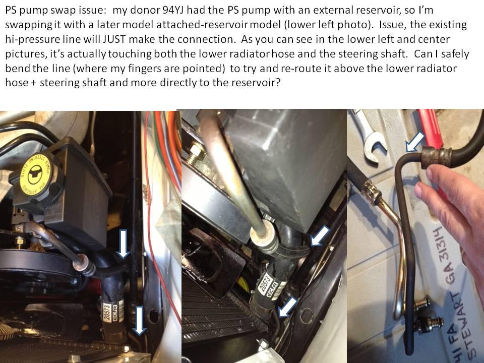
I'm wondering how safe it is to bend the hard part of my original CJ high-pressure line to fix this routing problem. You can see the current routing of the line with the white arrows. I'm trying to get it above/around the lower radiator hose and the steering shaft:

YJPSpumandCJhipressureline_zps103eaa25-1.jpg
 
what's next

I have a "punch list" that's growing by the moment but, as far as the engine swap and getting-it-running, I need to wire the VSS, the CPS, ground the park signal, and a few other small others (CEL signal, etc)

I still need to route the fuel lines in the engine compartment, re-prime the engine oil (did this about 15 months ago, so I want to do it again before I start it), check all the other fluids and go back through and check a bunch of my bolts/torque... etc etc..

I'll document as I go.
 
When I went to Oreilley's for the oil pressure sending unit, I came across the same issue. The blade terminal unit was only one part number (higher or lower-cannot remember). Same specs, different connector. I believe it was from a late 70's CJ 4.2L. Works pefectly.
 
question on the starter...

I'm using the CJ starter/bellhousing/flywheel on the YJ 4.0. The YJ had a multi-pole starter connection, including the large gauge red power lead and the grey signal from the starter relay in the PDC. The CJ starter has only the attachment for the large red power lead.

Do I need the signal from the YJ starter relay? If so, do I simply stack it with the red/power connector to the the 3/8 inch bolt on the CJ starter? Or do I eliminate the brown signal from the YJ relay?
 
Back
Top