Others I still need to figure out: VSS (I have the HESCO adapter on the front dampener).
The VSS is mounted to your transfer and the CPS is on the damper, you may need to lenghten the cps wire.
The VSS, You need to get one with the electrical and mechanical hook up if you plan on using the CJ speedo. One from a 91 YJ will work, and from a late 80's Dodge Dakota.
I used the late model dodge dakota as it was the cheapest.
Found a little more notes for you that might help you see below for fuel pump in 4th comment and #4 comment
1st, Label all the engine related connectors, including the VSS.
2nd, Remove all the flex-loom and electrical tape. A large portion of the harness will simply "fall out" as the headlight, horn, heater and all non-engine related wiring shares the flex-loom but is not integrated into the F.I. portion.
2nd, Some non-engine related systems are hard wired to the PDC, (reason for labeling) those can be removed later once the engine is running. There are a few points where engine and non-engine systems are connected so don't cut yet, we'll get to that later.
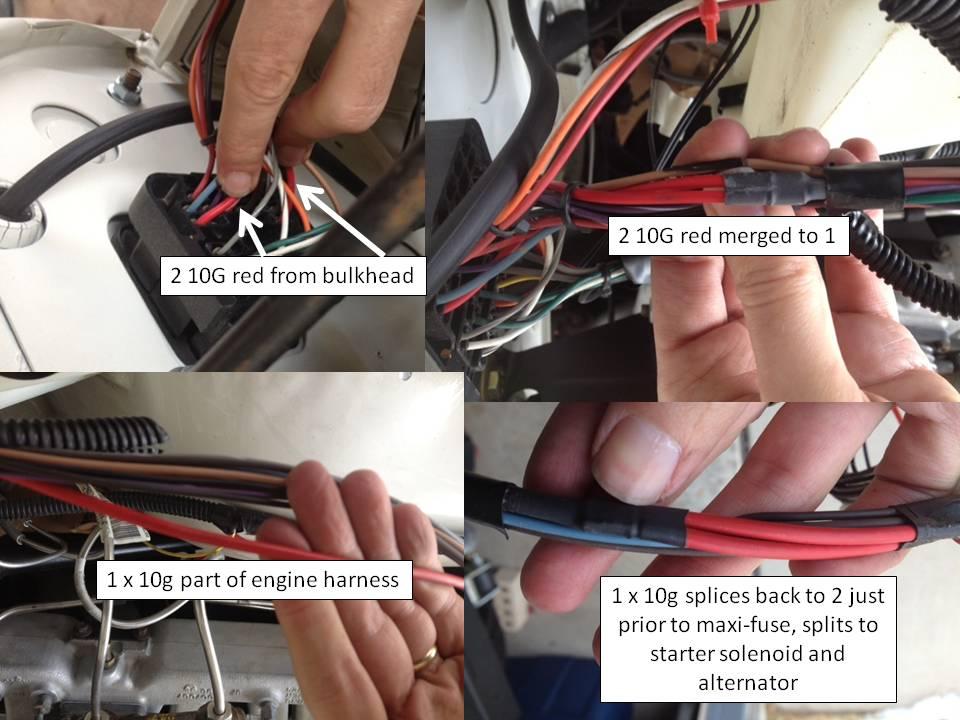
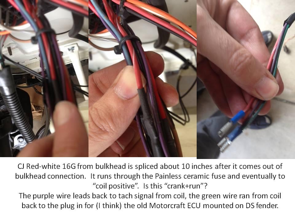
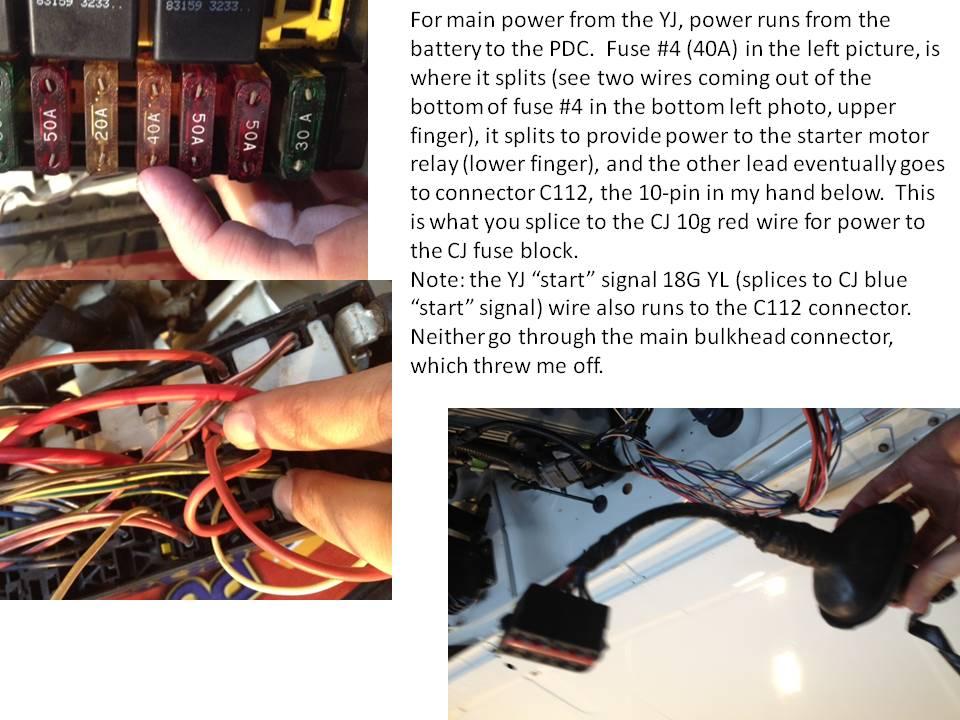
3rd. The flow of power goes like this. Battery to PDC, PDC to Ign. Switch. Your battery cable provides power to the PDC, a 12g Red/white power feed runs to the bulkhead connector. This ties into your existing CJ 10g Red that fees the Ign. switch.
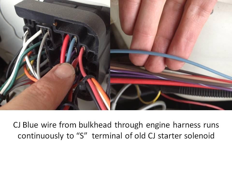
Two feeds come back out of the switch, the original blue (start) and red (run) from the CJ that powered the Duraspark module and solenoid. These two get spliced into the donor harness for the same purpose.
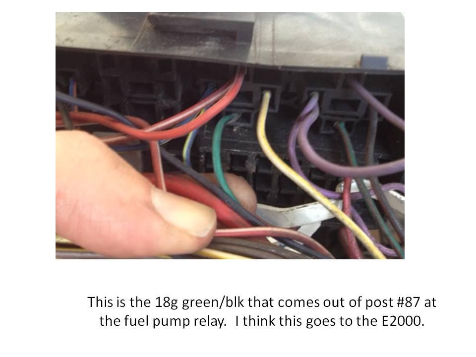
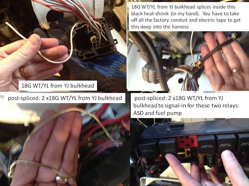
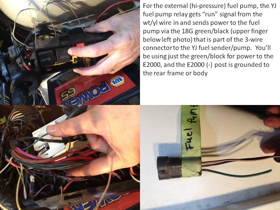
4th You must find the 12V power wire from the fuel pump relay and splice that into the fuel pump feed.
Start with that and we'll progress from there once you have everything identified.
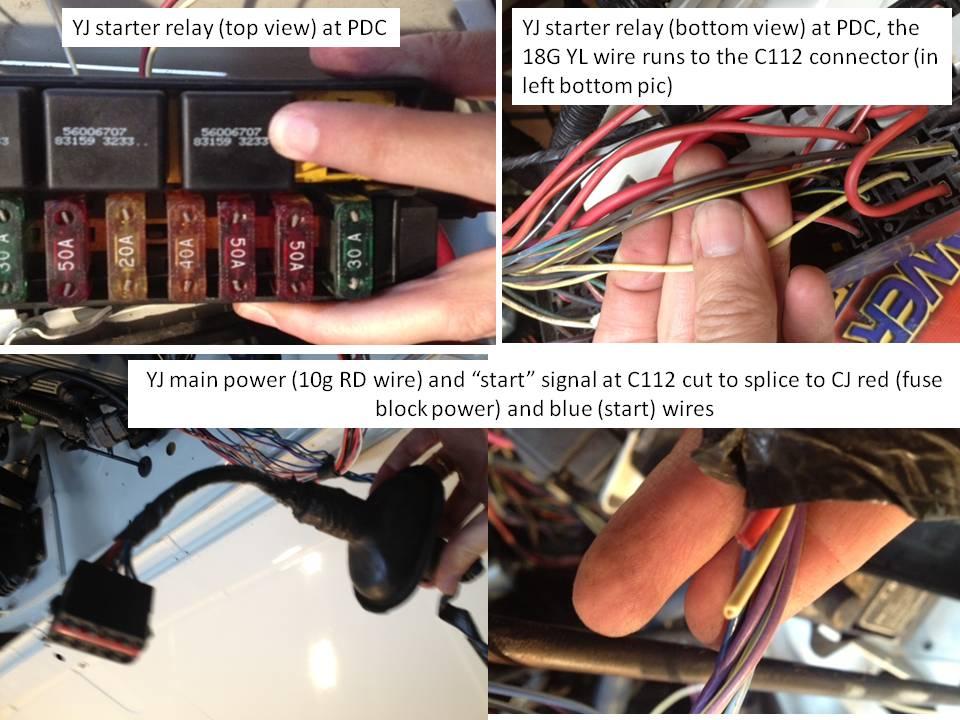
1) CJ cavity AX (Light Blue) Start out to ZJ Wire A41 16ga Yellow/Darkblue (PDC Engine starter motor relay) (cavity 26 YJ PDC circuit A41 yellow ignition switch output (start))
2) CJ cavity BW (Red/White) ignition on power feed out to ZJ Wire A21 12ga Darkblue/Gray (provides ignition on power to the PDC) (cavity 6 YJ PDC circuit G50 white/yellow fused ignition switch output)
3) CJ cavity EY (Red) hot battery feed in to ZJ Wire A2 10ga Pink/Black (always hot power from the PDC to the ignition)
(may also have used A1 12ga Red/White, but I decided to use a larger gauge power feed wire) (A1 circuit red wire feeds into a 40amp maxi fuse marked ignition system then doubles over to the starter relay)
4) ZJ A64 14ga Orange/Darkblue switched power feed to electric fuel pump.
This comes from the PDC fuel pump relay. Does not map to any CJ circuits. (Cavity 9 YJ PDC circuit A141, 16g DG/BK fuel pump relay output)
5) Battery + to PDC wire A0 6ga Red --> This is the existing ZJ wiring. (same)
6) Battery - to ground. wire Z0 6ga black --> this is the existing ZJ wiring. (same)
7) Ground the Park/Neutral sense wire (T41 20ga black/white - middle wire of connector C171 at the transmission) (same)
8) PCM MIL wire (G3 20ga black/pink CAV 32 Connector C141) will be used for a 'Check Engine' light (same)
9)Tach signal cavity 43 gray/light blue G21