Here's the saga of the tranny shifter. One of the things I loved about the AW4 (other than overdrive) is that it's an electronically controlled tranny. Ultimately, I want to have the manumatic shifter for the AW4 that lets you use full auto or manual shifting, something like this:
http://radesignsproducts.com/default.aspx
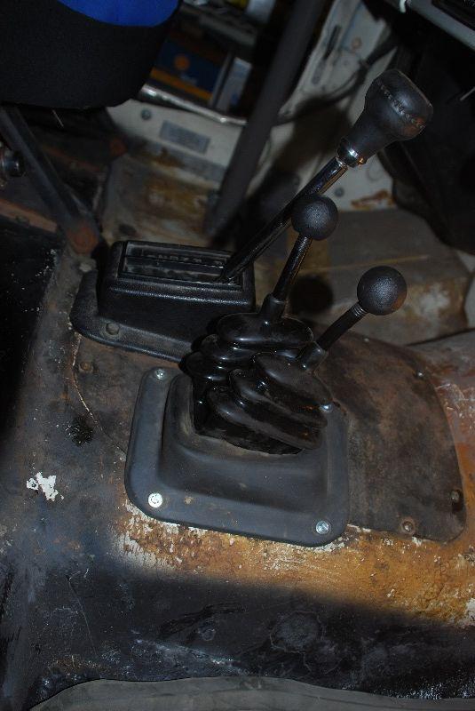
That said, one of the cool (to me) features of the Alaskan Postals is the floor shifter for the 999. Since the steering wheel is on the wrong side, the standard column shifter wouldn't work without some bizarre linakges/bracketry. I really wanted to try to keep the floor shifter, even if it wouldn't shift into all of the gears (because with the manumatic deal, you just use the real shifter to put it in D, and switch to another shifter/buttons/paddles to actually shift between gears in manual mode)
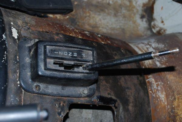
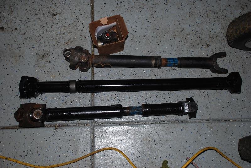
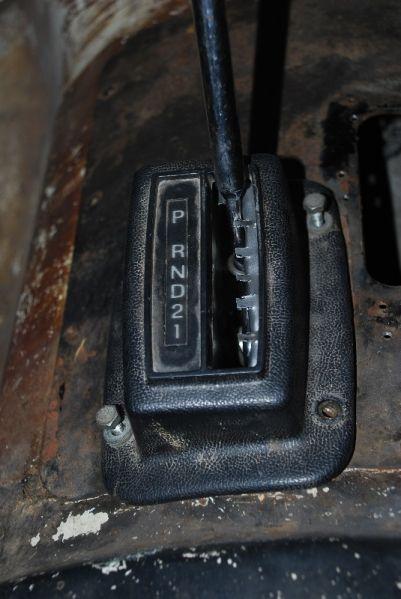
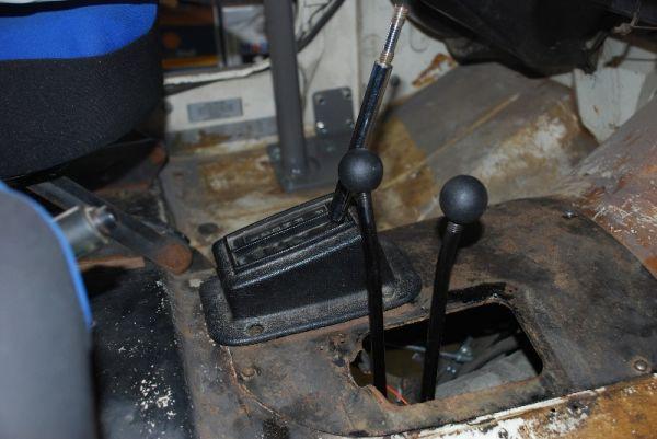
Floor shifter:
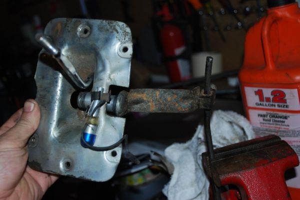
This is the business end:
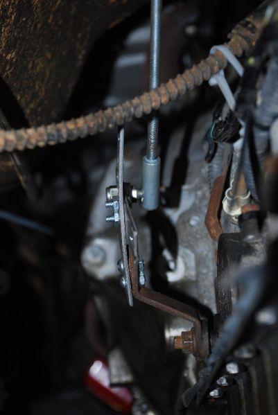
Luckily, the direction that the pivot goes on my floor shifter matches the way the AW4 needs to be shifted. So it's a matter of getting a linkage between the two that's located properly and transmits the force from the shifter in the proper direction to move the tranny shifter arm.
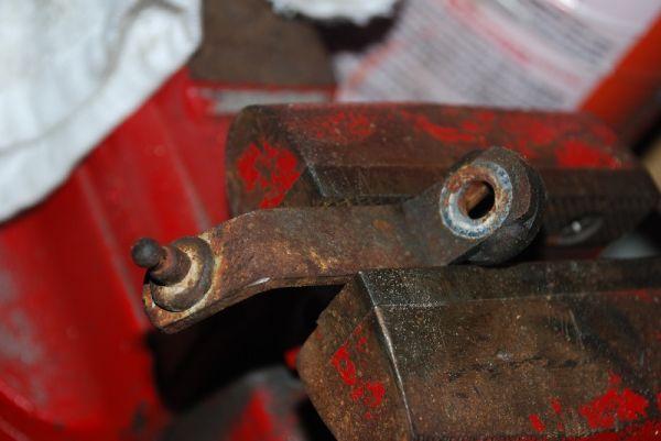
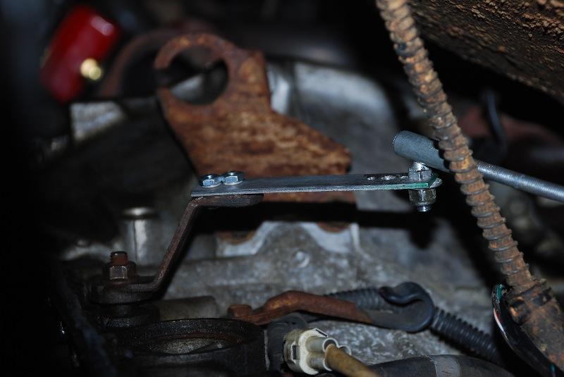
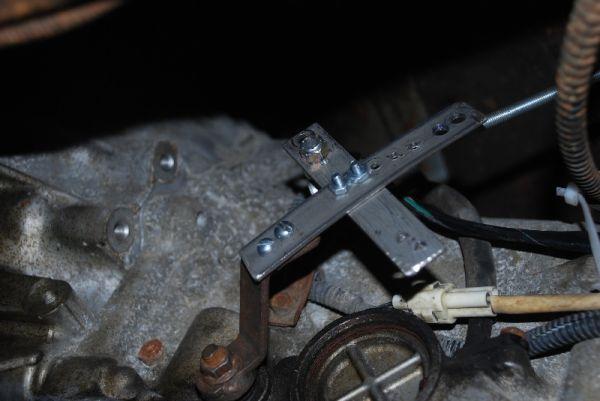
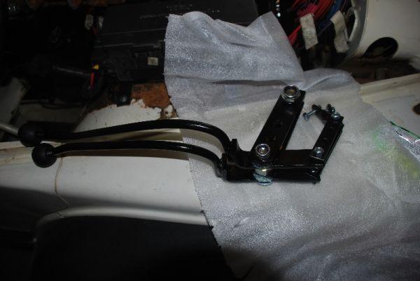
Here's the tranny shifter arm, removed from the tranny.
I eyeballed the amount of throw needed on the shifter arm to match what I was going to have from the floor shifter and cut a piece of flat stock to add to the arm. Had to remove the stock shifter cable ball and drill a couple holes to fit them up. If I ever get this set up just right, I can come back and weld them together. I forgot to take a picture before it was installed. I've since cut a new extension slightly longer and angled more to the front of the Jeep which works better, but still not perfect.
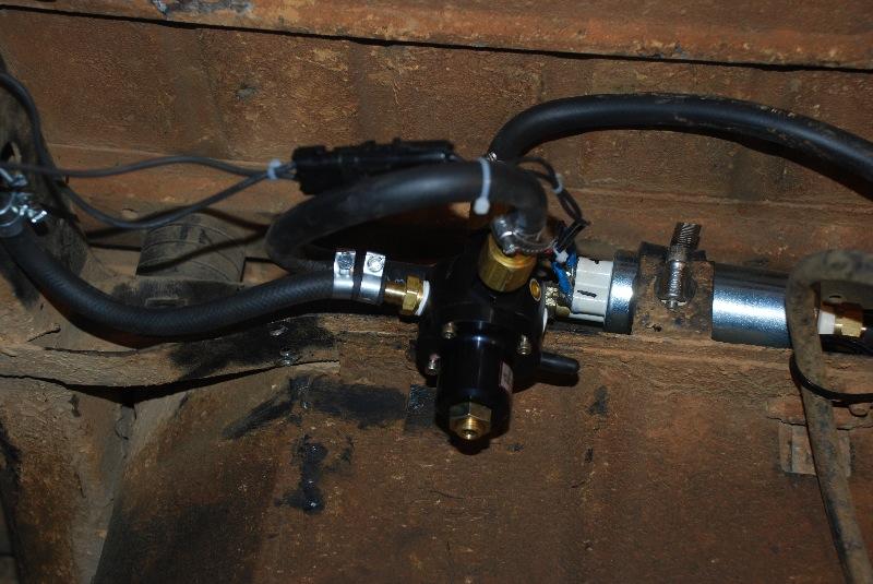
I'm using threaded rod which is a perfect replacement for the shifter rod that was used with the 999, so it clamps right into the shifter end of things. On the tranny end, I found a nice ball/socket connector that threads onto the rod. The ball stud is permanently mounted in the socket, all you do is drill a hole in the arm and bolt it in.
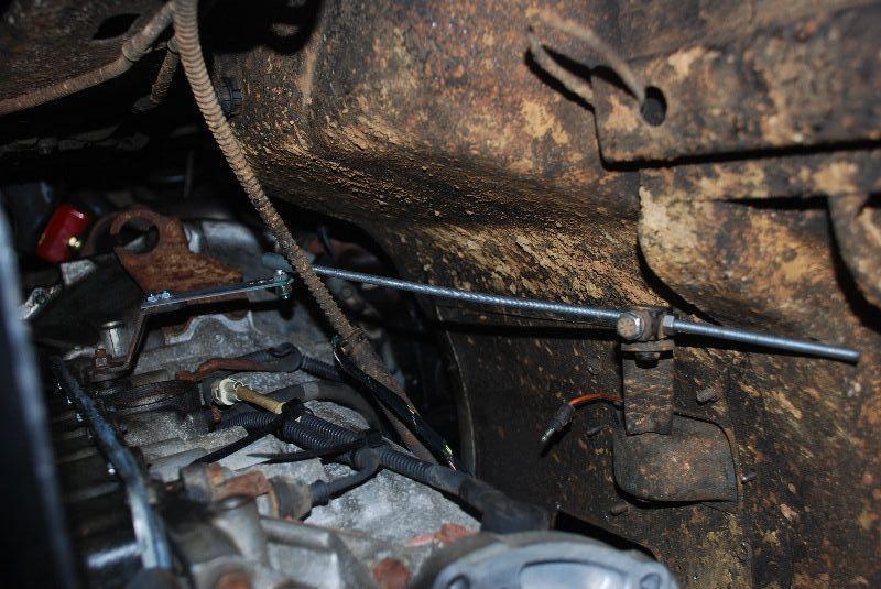
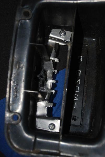
From here it's a matter of playing with the pivot points and rod length to try to match up the tranny shifter positions with the shifter gate. I'm not done trying to work on this (think the tranny ball stud needs to be moved closer to the tranny), but I'm thinking I may have to cut out the gate in my stock shifter cover and make up a new one. I'm thinking some flat plate bolted/JBWelded to the underside of the shifter cover might do the trick. This shifter is utterly simple, with just a spring putting force to the shifter arm to push it to the right. It relies completely on the shifter gate to hold it in place and the gate isn't "deep" enough to really hold it well, so my gate might be a nice improvement.
I also have it where it shifts great from R-N-D-3, but P to R is very difficult because of the angle between the shifter rod and the tranny shifter arm when in P. There's also not enough throw to get it into 1. I need to move the tranny shifter arm ball closer to the tranny so less throw will get it to shift.
so the saga continues...

") ). But I'm dying to get this thing out on the road and then the trail!!! Sucks that we're heading out of town this weekend
). But I'm dying to get this thing out on the road and then the trail!!! Sucks that we're heading out of town this weekend