• Notice for iPhone users: DO NOT use the image size reduction option when uploading photos to the forum. This causes portrait images to post as landscape. We have added a warning to the image insert pop-up as well.

1982 "Vintage Red" CJ-7 Renegade

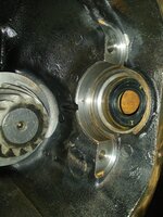
This tool works well for inside seals

This one is less expensive but I have not used…
I looked at both of those, pretty sure I can accomplish the same thing with a seal driver and a piece of all-thread, guess I will find out :fingerscrossed:
 
So, the home made install tool will work, just not as elegant as the dedicated tool for the job.

Instead of "pushing" the seals into place, I "pulled" them into place.

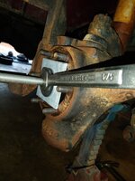
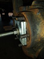
I used a piece of 3' long, 1/2" diameter all-thread. The 3' is a little long for the short side, but a good length for the long side.

Over all shot of the "install tool" in position:

20220217_165149.jpg


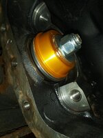
Using a seal driver to pull the seal flush with the end of the tube, step 1:

20220217_165157.jpg

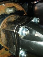
I used two pieces of 1/4" plate that I found at work, I believe they are some sort of sill/header plate washer, to pull against. They fit perfect between the knuckle spindle studs. At first I used one, but then I added the additional plate and washers so that the 3/4" wrench could be rotated almost 360 degrees, clearing the caliper mounting bracket.

20220217_165204.jpg

20220217_170717.jpg

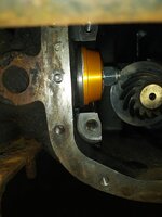
I then broke the tool down, reinstalled it, and finished the process by using an old bearing race to finish pressing the inner seal into place.

20220217_170725.jpg

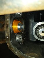
IMO, if you use a socket/piece of tube INSIDE the seal to drive/pull it into position, you will damage the seal. The OD of the metal seal casing is 2-1/8". The old race I used was exactly the same. In the picture above, I am using the orange seal driver to pull the race against the seal, pulling the whole assembly into position.

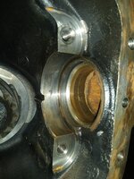
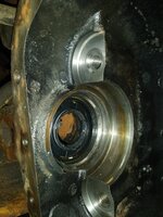
Success, the seal is all the way in, and perfectly "square" in the bore. Note the gap between the back of the race and the cast in place piece of axle housing in the picture below, perfect:

20220217_170742.jpg

I was using a piece of 1/2" all thread to pull the seal into place, You can obtain a whole lot of force with a 1/2" bolt. The "tool" above worked, but it was not like I was spinning that 3/4" wrench with one finger. It takes a lot of force to pull that seal into position. IMO, no way you can successfully beat this seal in with a hammer. The correct tool, or the home made tool above, is the way to go IMO.

Also, by using a "tool", you can adjust the seal depth in the bore. So, if your axle has a bad groove where the seal rides, set the seal shallower so that it rides on a smooth piece of the shaft/seal surface.

The biggest PIA with installing these seals, correct tool or home made tool: When you start the seal, it better be 100% straight. If you start to pull it in crooked, it will not straighten out. You have to stay on your toes, make damn sure that seal is going into the bore square. If not, game over. The seal will be smooshed out of round and ruined.

That is why I only have pictures of one side up - I ruined the second seal. It started a hair crooked, I figured it would straighten up. Nope.

So, I will have ruined two seals to install two seals.

Next time I do this, I will buy the correct tool. BUT, even with the "correct" tool, that seal has to start and stay square. No second chances.
 
Looks like that correct tool is a lot shorter than the 3 foot threaded rod. Whats up with that. I fully understand how yours works I believe. Yours pulls and the other pushes ?
 
Sanded, cleaned, and oiled the bore:

20220218_132458.jpg

Success, 2nd seal installed:

20220218_141144.jpg

The next time I install inner axle oil seals I am going to buy the "proper" tool.

Greased up the lips of the new seals. I would not recommend greasing the shafts, good chance they will pick up some crud going through the axle tubes and ruin the new seals.

20220218_151718.jpg

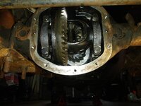
Reinstalled the front differential:

20220218_154352.jpg

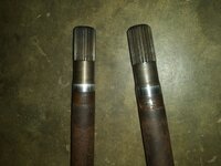
Make sure the axle shafts are clean/smooth wear they ride in the axle seals. If not, you could either adjust the seal depth, or install "speedi-sleeves" over the axle shafts. Or, upgrade to stronger axle shafts.

20220218_154740.jpg

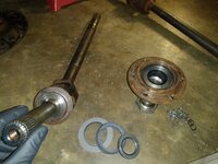
Prepping the stub shafts and spindles before installing the axle shafts:

20220218_155413.jpg

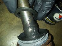
Installed a new rubber inner and outer spindle seal. Place the plastic thrust washer with the chamfer cut toward the u-joint. Add grease like so:

20220218_155614.jpg

Inner spindle seal in place. I put anti-sieze on the spindles where they slide into/against the knuckles.

20220218_155951.jpg

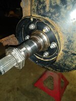
Slide the axle shafts into place, then install the spindles:

20220218_160251.jpg

Install the splash shields, torque the self locking nuts to 35 foot pounds.

20220218_163121.jpg
 
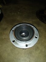
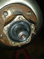
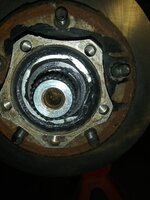
Slide on the rotor hub, take care not to let the outer bearing fall out.

20220218_172154.jpg

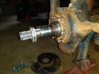
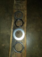
Spindle nuts and washer, install in order from top to bottom:

20220218_173607.jpg

1) Thick thrust washer
2) Inner nut, torque to 50 foot pounds, back off a hair
3) Intermediate washer
4) Outer nut, torque to 50 foot pounds

Installed, bent one portion of the intermediate nut over a flat of the outer nut to prevent it from backing off:

20220218_190018.jpg

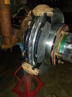
Brake pads and anti-rattle clips:

20220218_193451.jpg

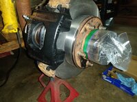
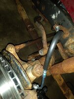
Brake calipers and new rubber brake lines:

20220218_193828.jpg

20220218_203442.jpg

Started cleaning the lock in hubs:

20220218_203505.jpg

Unfortunately for me, the lock in hubs wil have to be completely disassembled and cleaned. The old grease is like thick wax. If I don't completely remove it and re-lube the hubs, I am scared they are going to break. It takes too much force to twist the dials. I haven't found any online " how to guides", and I have a feeling these things are pretty particular on how they reassemble, especially the dials.

Left it like this:

20220218_212417.jpg

Still need to:

Clean/lube/install lock in hubs
Bench bleed/install new master cylinder
Bleed brakes
Add gear oil to both differentials
Add tires
Finish this phase!!!!

That's it for now!!!
 
I haven't found any online " how to guides", and I have a feeling these things are pretty particular on how they reassemble, especially the dials.
Maybe this will help.
Ignore the confusing changing terminology and just follow the steps. It looks fairly straight forward when you see how it comes apart and the logic of how it functions.
 
Standard lockouts? The hardest part is ruining the OEM 4x sticker to get to the screw to disassemble the things :cry:

20200620_203749_resized-jpg.84581
 
Last edited:
Got a bunch of work completed Saturday, I'll let the pictures do the talking for most of this.

Filled both diffs with new gear oil (added LSD additive in the rear):

20220219_095512.jpg

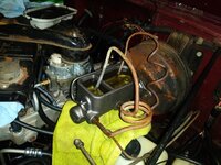
Bench bled and installed the new master cylinder (my old brake lines work perfect for this!!):

20220219_095521.jpg


I also completely disassembled/cleaned/lubed/rebuilt the OEM front lock in hubs.

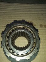
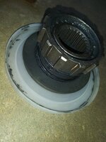
The "inner" portion of the hubs is a no brainer. The pic below shows one completed/one disassembled "inner" portion:

20220219_112657.jpg

In the picture above, two "stacks", left and right.

Left stack:

1) Put gear thing (top piece) into middle grey plastic piece as shown
2) Reinstall thin washer, then retaining clip

Then, Right stack assembles into Left stack:

1) Place big spring on Left stack
2) Place gear on top of spring (note orientation, install as shown)
3) Push gear down with fingers, install clip

Finished with the "inner" portion. Pretty easy, just pay attention to orientation of parts. You can also leave one assembled for reference as you assemble the other one.

The below pictures may be helpful.

The snap ring installed, Right Stack, step #3:

20220219_112704.jpg

Washer and snap ring installed, Left stack, step #2:

20220219_112718.jpg

Orientation of right stack on top of left stack:

20220219_112725.jpg

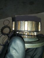
Picture below just shows the retaining clip installed. It also shows how the hubs operate - twist the dial, it forces another spring inward, pushes the two metal gears of the inner hub together, locking the hub/wheel hub to the axle shaft.

20220219_112733.jpg

All the above pictures were taken with the hubs "dry". I lightly greased all the hub parts with the same grease I used on the wheel bearings. Light coat, DO NOT pack the hub components full or they will not function.

20220219_113514.jpg

This concludes the "inner" portion assembly.
 
The "outer" hub portion was the part I was worried about. I had read somewhere (hint, the internet) that this was super big PIA and if you do not install the parts precisely they will not function. Partly true, kind of, not really, no hill for a stepper, I will explain.

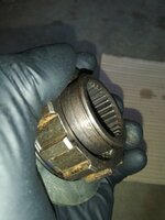
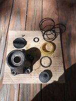
All of the "outer hub parts:
20220219_130202.jpg

Mostly in order in the above picture (the o-ring installs on top of the grey plastic piece pictured bottom right). Those two grey plastic things are the only tricky part, I will explain in a bit.

Put the dial into the hub body, point it to the "2wd" position as shown.
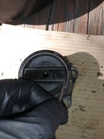
20220219_131948.jpg

Flip the hub over, holding the dial in the "2wd" position, note how the hex points. Note how one of the "points" of the hex is pointing right at the specific end of the dial.
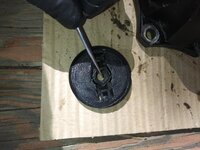
20220219_132003.jpg

On the grey plastic piece that will eventually be installed, it's built in hex MUST line up with the dials hex. You have some wiggle, BUT you don't want to wiggle a lot. It takes some trial in error, I'll explain in a bit. In the picture above, the "point" of the hex is pointing to the portion of the dial that will be pointing at the "2" or the "4" on the hub body. For reassembly, point the dial at the "2" position.

All the parts lightly greased. Note the upside down dial AND the assembled grey portion. These two pieces are the key to the puzzle. Also not my "assemlby tool", a socket on an extension, more on this in a bit.
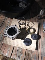
20220219_132438.jpg

The picture below is the most important:
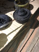
20220219_132447.jpg

This assembly is composes of the two grey pieces - an outer ring and an inner hub. In the "2wd" position, this outer ring is near the top of this hub. I can NOT tell you exactly where, it will take some trial in error. Get it close like the picture above.

This assembled grey piece slides inside the yellow plastic piece. The yellow piece has internal "ridges" that will engage into the grey outer rings slots. You have some "wiggle" here. You want to install the grey piece into the yellow piece, align the yellow pieces outer nubs with the internal slots of the hub body. Then, you can fine tune your hex alignment by screwing that inner grey ring up or down slightly to ensure the hexes line up.
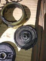
20220219_132451.jpg

It is hard to explain in words, sounds like a PIA, but it is not. When you have the parts in front of you, clean and dry, go through a few trial runs. You will see how it all fits together and operates.

Hub dial on hub body, pointed at 2wd. Spring on to of yellow plastic part (spring has a big and little end, will only go on one way). Note how the hexes line up.
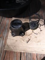
20220219_132547.jpg

When you go to install the plastic/spring assembly into the hub body, kind of PIA. Spring is tight, and you have to compress the entire assembly deeply into hub body. This is where my "tool" comes in handy. Place the assembly on the socket like so:
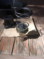
20220219_132623.jpg

Note the hex orientation:

20220219_132636.jpg

Gently slide/line up the hub body with the nubs on the yellow plastic thing, push down, when the inner grey part hex goes into the dials hex, install screw, finished:
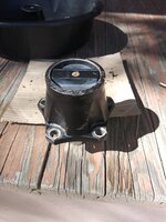
20220219_132740.jpg

Sounds terrible, it is NOT that bad. The only "fiddly" bit - the grey outer ring on the grey hub. Test your hubs. IF the dial does not want to go all the way into 2wd or 4wd, you will need to take it back apart, move the grey ring a little bit up (for better 2wd engagement) or down (for better 4wd engagement). I had to take each hub apart one time for a minor adjustment/reassembly, and they both work perfect. The dial positively "cam" into each position, dial moves easily.

Sounds awful, really not that bad. It took longer to clean all the parts up then it did to figure out how they work/reassemble.

All of the internal hub components were in great shape, the bolt holes in the hub bodies were also still round (not egged or boogered all up). If your OEM hub bodies are trashed, I would not waste time rebuilding them. If the outer aluminum hub body is damaged, especially the 5 mounting holes, probably a waste of time.

 
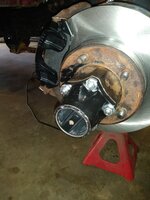
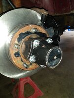
I did not want to just simply bolt the hubs back onto the wheel hubs with the OEM bolts. The bolts always come loose. When the bolts loosen, the lock in hub will start to rock back and forth, "egging" out the mounting holes. Once this happens, they are trashed, and will usually explode at the least opportune time.

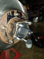
I installed studs on my green Scrambler, did the same thing here:

20220219_144301.jpg

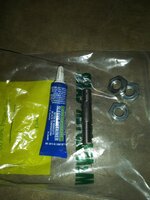
The longer portion on the stud gets threaded into the wheel hub. I used Sleeve Retainer (read Red Loc-Tite on steroids!!!) to secure the studs into the wheel hubs.

One big note - the studs smooth center part has a slightly larger OD then the threaded portion on a 3/8" bolt. This is what you want. These fat centers positively locate the lock in hub on the wheel hub. There is no wiggle room between the studs and the lock in hub body. This keeps the hub from rocking at all. Your lock in hub bodies mounting holes must still be round for this to work. On one of mine, I had to lightly file the 5 mounting holes of one of the lock in hub bodies for it to slide over the studs. This hub had started to "rock", leaving light threads in what is supposed to be a smooth bore. The threads on the OEM bolts will cut threads into the hubs cast aluminum body.

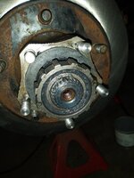
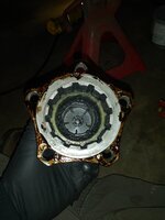
The inner hub portion installed, five studs installed. I used grease to seal the plastic base to the hub body. How this piece locks into the wheel hub, I see no reason for silicone. IF all the OEM parts are still in good shape, grease will seal the fitment. Don't forget the snap ring on the end of the axle shaft that secures this assembly to the axle shaft!!!

20220219_144254.jpg

20220219_144618.jpg

I used aviation sealant to help seal the hub body to the wheel hub. Again, how the hub parts key on to that grey plastic base of the inner hub, no real reason to goop it all up. The inner machined ring of the lock in hub fits onto the plastic base, sealing it up.

20220219_150608.jpg

Tight fit, but it slides over the studs. You do not have to beat it on or pry it off, but it is a tight fit, which is what you want.

20220219_151939.jpg

And I uses self locking nuts to secure the hub body to the studs:

20220219_155744.jpg

20220219_155750.jpg

With the studs keeping the hub bodies from rocking, and the metal self locking nuts positively clamping the lock in hub to the wheel hub, not sure how much stronger you could make the 5 bolt hub assembly?

Fine for up to 31" tires and an OPEN differential. Add a locking diff, larger tires, probably on borrowed time. That being said, I do not think the hubs will come loose from the wheel hub and fail!! They will now only fail due to the inherent weakness of the cast aluminum hub body.
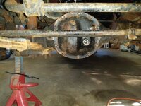
I gravity bled all the brakes. Pumped the peddle, was soft. Had one leak - passenger side rear, metal line to wheel cylinder. I had to use small Vice Grips to tighten this line up a bit, no more leaks. I boogered this fitting up a little removing it with the "correct" line wrench. It is still serviceable, so I'm going to let it slide. AND, if you have to change one metal brake line, this would be the one (short and easy to get to!!!)

This will hopefully conclude my axle/brake work on this project.

I have a few more easy things to fix, then it goes to Baton Rouge, FINALLY!!!!!!!!!!!!!!!!!!!!!!!!!!!!!!!!!!!!!!!!!!!!!!!!!!!!!!!!!!!!!!!!!!!!!!!!!!!

Unfortunately, either the transmission or transfer case decided to start puking fluid all over the garage floor. So one more "major fix", could be easy, could be PIA, will have to investigate.

That's it for now :thumbsup:
 
Probably read the same. Was super paranoid and careful on disassembly only to find that it really wasn't that bad. Like the wheel hub studs. Makes sense and looks good. Have to file it away in the 'to do' list.
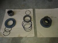
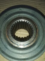
 
I think this was covered the last time, Nobody is currently making a good set of replacement hubs ? I think i searched pretty well what you recommended but came up empty.
 
I think this was covered the last time, Nobody is currently making a good set of replacement hubs ? I think i searched pretty well what you recommended but came up empty.
On my green Scrambler, I found a set of NOS Superwinch hubs on eBay. I ran the 6 bolt version of these over 20 years ago on my '78 CJ7(s). Never broke a set, BUT open differential, 33" tires. I gave them hell back then, too LOL!!!

The Superwinch hub body is steel IIRC, stronger then the cast aluminum pot metal of the OEM hubs. Added bonus - the Superwinch hubs will work with the OEM center caps.

I think Mile Marker still makes hubs for CJ's, and Warn. BUT, neither will work with the OEM center caps, without serious modifications.
 
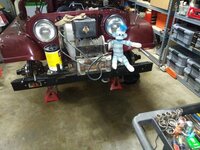
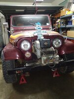
Picked up a hitch hiker on the ride home from Baton Rouge yesterday!!!!!

20220221_175831.jpg

He helped me bleed the brakes. I hosed all the brake fluid off the underside to keep it from stripping paint. Of course, this made a big mess that I did not want to lay in to investigate the transmission/transfer case leak.

Put the tires back on, called it a night!!

20220221_185550.jpg

That's it for now :thumbsup:
 
Picked up a hitch hiker on the ride home from Baton Rouge yesterday!!!!!

View attachment 100738

He helped me bleed the brakes. I hosed all the brake fluid off the underside to keep it from stripping paint. Of course, this made a big mess that I did not want to lay in to investigate the transmission/transfer case leak.

Put the tires back on, called it a night!!

View attachment 100739

That's it for now :thumbsup:
That parts monkey is like the North Star 🐒
 
Back
Top