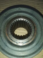
The "outer" hub portion was the part I was worried about. I had read somewhere (hint, the internet) that this was super big PIA and if you do not install the parts precisely they will not function. Partly true, kind of, not really, no hill for a stepper, I will explain.
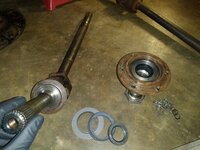
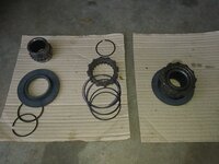
All of the "outer hub parts:
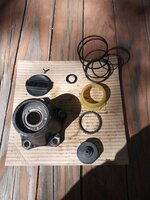
Mostly in order in the above picture (the o-ring installs on top of the grey plastic piece pictured bottom right). Those two grey plastic things are the only tricky part, I will explain in a bit.
Put the dial into the hub body, point it to the "2wd" position as shown.
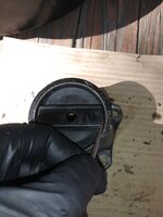
Flip the hub over, holding the dial in the "2wd" position, note how the hex points. Note how one of the "points" of the hex is pointing right at the specific end of the dial.
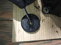
On the grey plastic piece that will eventually be installed, it's built in hex MUST line up with the dials hex. You have some wiggle, BUT you don't want to wiggle a lot. It takes some trial in error, I'll explain in a bit. In the picture above, the "point" of the hex is pointing to the portion of the dial that will be pointing at the "2" or the "4" on the hub body. For reassembly, point the dial at the "2" position.
All the parts lightly greased. Note the upside down dial AND the assembled grey portion. These two pieces are the key to the puzzle. Also not my "assemlby tool", a socket on an extension, more on this in a bit.
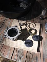
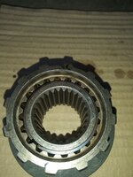
The picture below is the most important:
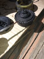
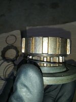
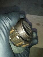
This assembly is composes of the two grey pieces - an outer ring and an inner hub. In the "2wd" position, this outer ring is near the top of this hub. I can NOT tell you exactly where, it will take some trial in error. Get it close like the picture above.
This assembled grey piece slides inside the yellow plastic piece. The yellow piece has internal "ridges" that will engage into the grey outer rings slots. You have some "wiggle" here. You want to install the grey piece into the yellow piece, align the yellow pieces outer nubs with the internal slots of the hub body. Then, you can fine tune your hex alignment by screwing that inner grey ring up or down slightly to ensure the hexes line up.
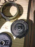
It is hard to explain in words, sounds like a PIA, but it is not. When you have the parts in front of you, clean and dry, go through a few trial runs. You will see how it all fits together and operates.
Hub dial on hub body, pointed at 2wd. Spring on to of yellow plastic part (spring has a big and little end, will only go on one way). Note how the hexes line up.
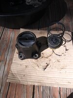
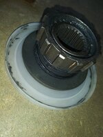
When you go to install the plastic/spring assembly into the hub body, kind of PIA. Spring is tight, and you have to compress the entire assembly deeply into hub body. This is where my "tool" comes in handy. Place the assembly on the socket like so:
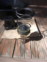
Note the hex orientation:
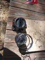
Gently slide/line up the hub body with the nubs on the yellow plastic thing, push down, when the inner grey part hex goes into the dials hex, install screw, finished:
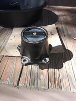
Sounds terrible, it is NOT that bad. The only "fiddly" bit - the grey outer ring on the grey hub. Test your hubs. IF the dial does not want to go all the way into 2wd or 4wd, you will need to take it back apart, move the grey ring a little bit up (for better 2wd engagement) or down (for better 4wd engagement). I had to take each hub apart one time for a minor adjustment/reassembly, and they both work perfect. The dial positively "cam" into each position, dial moves easily.
Sounds awful, really not that bad. It took longer to clean all the parts up then it did to figure out how they work/reassemble.
All of the internal hub components were in great shape, the bolt holes in the hub bodies were also still round (not egged or boogered all up). If your OEM hub bodies are trashed, I would not waste time rebuilding them. If the outer aluminum hub body is damaged, especially the 5 mounting holes, probably a waste of time.