• Notice for iPhone users: DO NOT use the image size reduction option when uploading photos to the forum. This causes portrait images to post as landscape. We have added a warning to the image insert pop-up as well.

1985 4 cylinder Base Model CJ-7

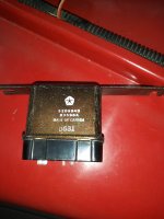
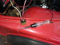
Ok, to the best of my knowledge, and after experimentation, the damaged piece below is indeed the choke relay for the AMC 2.5:

2.jpg

The plug from the wire harness that plugs into the relay:

1.jpg

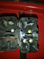
The contacts are dirty/slight corrosion, so I popped each one out, one at a time, and hit them with some sand paper:
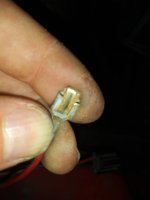
3.jpg

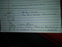
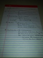
My notes:

5.jpg

On the 258, their is an oil pressure switch that ties into the choke relay. On the AMC 2.5, no oil pressure switch. So, the brown wire from the alternator is what tells the relay to open, an allow battery voltage to flow to the choke. Both accomplish the same thing: IF the engine is not running (either via oil pressure present or alternator spinning/charging), the relay will NOT open. In this way, IF the key is left ON, engine not running, the choke will not be energized, which is what you want.

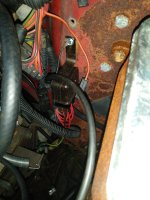
One confusing wire issue: it is a red wire with white strip that runs through the harness all the way to a black plastic plug near the carburetor. On the other side of this connector, the red/white stripe wire changes to a solid blue wire which plugs on the choke.

6.jpg

Made a quick "RedneckRay" jumper wire, choke works for now, BUT it will stay energized anytime the key is left on:
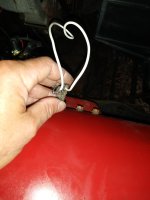
4.jpg

I will install my "replacement" relay once it arrives.

I am curious IF a relay has to have a ground to operate? I am not an expert, but this is a simple 3 wire relay:

1) Red Wire - power with key ON
2) Red/white stripe Wire - to choke
3) Brown Wire - from alternator

So, when #3 shows 12 volts at the relay, it opens and allows #1 to flow down #2 to the choke. Is a ground necessary? I guess I will find out!!!
 
This is the other strange relay device, I still want/need to trace out the wires to see exactly what it does:

7.jpg

8.jpg

Ahh, the good old days, when the Canadians made our doo-hickey's and what-not's!!!!!!!!!!!!!!

9.jpg

My wiring notes:

16.jpg

I have a feeling that the wires coming out of this doo-hickey jump to other doo-hickey's and then maybe to output devices? Not sure, need to research/find a 1985 AMC 2.5 wiring diagram.
 
The new doo-hickey:

10.jpg

11.jpg

Same as the old one, same patent #:

12.jpg

13.jpg

Bent the mounting bracket and installed it with one screw:

14.jpg

15.jpg

I no longer get the weird clicking sound, so that's good. I still need/want to figure out what exactly this does??
 
I am curious IF a relay has to have a ground to operate? I am not an expert, but this is a simple 3 wire relay:

1) Red Wire - power with key ON
2) Red/white stripe Wire - to choke
3) Brown Wire - from alternator

So, when #3 shows 12 volts at the relay, it opens and allows #1 to flow down #2 to the choke. Is a ground necessary? I guess I will find out!!!
The relay coil gets energized from the alternator (brown wire) and needs the ground to the other side of the coil to cause it to close the contact between #1 and #2 to feed to the choke.

choke.PNG
 
This is the other strange relay device, I still want/need to trace out the wires to see exactly what it does:

View attachment 104885

View attachment 104886

Ahh, the good old days, when the Canadians made our doo-hickey's and what-not's!!!!!!!!!!!!!!

View attachment 104887

My wiring notes:

View attachment 104888

I have a feeling that the wires coming out of this doo-hickey jump to other doo-hickey's and then maybe to output devices? Not sure, need to research/find a 1985 AMC 2.5 wiring diagram.
Now that you have a better pic of the wires and connections...
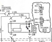
I'm more certain it's the "Anti Diesel Delay Relay".
It looks exactly like the wiring for the 2.5 in the '83 FSM.


Delay.PNG
 
Besides the electric choke not working, which I solved, mostly, the Sol-Vac is no longer functioning, either.

Besides the "odd" choke and anti-diesel delay relay (I say "odd because they do not resemble a "modern" relay", there are four "modern" relays in the wiring harness;

18.jpg

They may or may not have anything to do with the Sol-Vac, so I have been doing research. It has been raining everyday, so I have not had time to do any hand on work, so research.

Printed out the correct wiring diagram:

20220823_170029.jpg

Making notes:

20220823_174740.jpg

20220823_174750.jpg

20220823_174805.jpg

20220823_175837.jpg

20220823_213330.jpg

20220823_214609.jpg

I am "old school", so I tend to write/draw thing out to better understand them. I have been going through the wiring, mainly all six "relays", figuring out how all this stuff works/interconnected.

The Sol-Vac issue may just be a fuse, easy enough to check.
 
The "internet told me this relay will work in place of the the OEM metal relay with separate ground wire" relay was delivered the other day:

20220824_180121.jpg

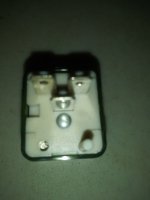
Unlike most relays, there is no pin ID, or schematic printed on this relay:

20220824_180144.jpg

20220824_180156.jpg

I wonder if the big silver round protrusion underneath the lower terminal is supposed to touch a ground?

This is a "common" Standard RY-144 relay. I found this schematic on Amazon, not sure if it is correct:

41P6Z8WQNYL._AC_.jpg

Not sure what all that means? Looks like #1 and #2 are the coil, which is connected all the time, then when #3 is energized it allows the coil to close completing the circuit? Just a guess at this point? I am to "assume" that this relay must ground itself, maybe into a metal relay holder?

The part number I ordered is a choke relay for say a 1981 Corvette. But, when you research this year Corvette, the wiring is much more involved. Yes, this relay is in the choke circuit, BUT the entire choke circuit on these cars also ties into the alternator charging/charging warning light circuit. So, not just specifically a direct choke relay.

Easy enough to plug it into the Jeep's wiring and see if the choke functions. If not, easy enough to cut the OEM wiring connector off, wire in a 4 pin relay, add a ground wire, to make the choke functional.

I am curious as to how this RY-144 relay functions????

Once the rain stops I will do some more hands on work.

That's it for now :wave:
 
You are very patient. That’s just 1 reason I went for a Weber a long time ago. I’ve got some relays also my buddy gave me decades ago I think were from an Audi at the time. :thumbsup:
 
Piddled with this one a little bit today.

Plugged the AC Delco three prong relay into the wire harness:

20220827_162822.jpg

Engine running, choke works:

20220827_162846.jpg

Not sure how this relay works without a ground, but it works.
 
  • Like
Reactions: SKT
Decided to bench test the other four relays that reside in the under hood wiring. Pulled/tested each of them one at a time. Some simple wires and a test light:

20220827_173932.jpg

Two of the four tested bad, and had physical signs of problems:

20220827_174511.jpg

The score sheet:

20220827_173944.jpg

While I had my test rig set up, checked another old relay, it was bad, too. Note the schematic printed on the relay.

20220827_174530.jpg

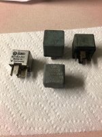
Two of the original relays were bad, a third was slow to respond. I changed out all four just to eliminate any problems. I used these relays:

20220827_174553.jpg

After all of that, the Sol-Vac still does not work. All fuses are good. I have 12 volts at the Sol-Vac connector with engine running. Need to check the wiring diagram, but maybe this Sol-Vac went bad. More testing/studying needed.

The engine is also running poorly. Easy/moderate acceleration is hard to do, bucking and missing. It will backfire out the carburetor while idling if you blip the throttle, sometimes.

Acting like a timing issue, but I think it is a carburetor/accelerator pump issue. Hard acceleration, no problem. Starts and stops fine, no run ons.

Will pull the carburetor off tomorrow and take a look, rebuild/adjust if needed. Then, recheck timing and adjust idle speed(s). And mess with Sol-Vac.

Depending on weather......

That's it for now :poop:
 
This is a "common" Standard RY-144 relay. I found this schematic on Amazon, not sure if it is correct:

41P6Z8WQNYL._AC_.jpg
Have you been able to confirm that this is how the relay operates?
(It has a totally different functionality if it is.)
Engine running, choke works:
Does the power to the choke go away when the engine is off?

Trying to wrap my head around how this is a replacement for the original relay. :shrug:
 
Have you been able to confirm that this is how the relay operates?
(It has a totally different functionality if it is.)

Does the power to the choke go away when the engine is off?

Trying to wrap my head around how this is a replacement for the original relay. :shrug:

It made me scratch my head a bit as well but i think this is how it works🤓

If the schematic for that relay is correct then as that relay makes a circuit when it is de-enrgised then I would hazard an educated guess that the connections are:
1 Alternator signal
2 +12Volt (ignition fed)
3 Choke connection

So turn the ignition on (engine off) and pin 2 gets +12Volts which feeds one side of the relay coil through the diode.
As the alternator is not generating yet but also has power then it is providing a ground signal to the other side of relay coil via pin 1 so it is energised and opens the relay and this cuts the power to pin 3 and turns the choke off.

Once the alternator gets charging the signal on pin 1 turns to +12 Volts and the relay denergises as it now has +12volts on both sides of the relay coil and so the choke gets power via pin 3 as the contact closes again.

Its back to front to a normal relay but would make sense so long as the +12volts on the relay is ignition fed or the choke would always be on and flatten the battery.
 
Have you been able to confirm that this is how the relay operates?
(It has a totally different functionality if it is.)

Does the power to the choke go away when the engine is off?

Trying to wrap my head around how this is a replacement for the original relay. :shrug:
Yep, no power to choke when engine/ignition off :thumbsup:
 
It made me scratch my head a bit as well but i think this is how it works🤓

If the schematic for that relay is correct then as that relay makes a circuit when it is de-enrgised then I would hazard an educated guess that the connections are:
1 Alternator signal
2 +12Volt (ignition fed)
3 Choke connection

So turn the ignition on (engine off) and pin 2 gets +12Volts which feeds one side of the relay coil through the diode.
As the alternator is not generating yet but also has power then it is providing a ground signal to the other side of relay coil via pin 1 so it is energised and opens the relay and this cuts the power to pin 3 and turns the choke off.

Once the alternator gets charging the signal on pin 1 turns to +12 Volts and the relay denergises as it now has +12volts on both sides of the relay coil and so the choke gets power via pin 3 as the contact closes again.

Its back to front to a normal relay but would make sense so long as the +12volts on the relay is ignition fed or the choke would always be on and flatten the battery.
The brown wire off the alternator is fed off the resistor wire, so it has some voltage with key on/engine off. Just to confuse the issue some more :crazy:
 
It made me scratch my head a bit as well but i think this is how it works🤓

If the schematic for that relay is correct then as that relay makes a circuit when it is de-enrgised then I would hazard an educated guess that the connections are:
1 Alternator signal
2 +12Volt (ignition fed)
3 Choke connection

So turn the ignition on (engine off) and pin 2 gets +12Volts which feeds one side of the relay coil through the diode.
As the alternator is not generating yet but also has power then it is providing a ground signal to the other side of relay coil via pin 1 so it is energised and opens the relay and this cuts the power to pin 3 and turns the choke off.

Once the alternator gets charging the signal on pin 1 turns to +12 Volts and the relay denergises as it now has +12volts on both sides of the relay coil and so the choke gets power via pin 3 as the contact closes again.

Its back to front to a normal relay but would make sense so long as the +12volts on the relay is ignition fed or the choke would always be on and flatten the battery.
I've since dug out my printed copy of the FSM and see that terminal #2 is fed from the ignition switch "Run" position.
My concern was the terminal was fed by a constant hot. :o
 
I've since dug out my printed copy of the FSM and see that terminal #2 is fed from the ignition switch "Run" position.
My concern was the terminal was fed by a constant hot. :o
It is still odd:

1) Ignition 12 volt power IN
2) Wire to choke OUT
3) Brown wire from alternator, which is part of the resistor wire circuit, so minor voltage key on, batt volt once engine running

No ground wire anywhere???
 
Back
Top