- City
- Richmond
- State
- TX
I’m at a loss how jumping the neutral safety switch fixed the lack of voltage in the switch circuit, but if it cranked by jumping the NSS the next step is to test if the switch is bad or if the transmission linkage is out of adjustment.
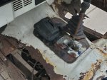
I would start by removing the interior shifter bezel. It should be floor mounted and look like this:

Removing the black bezel will reveal the shifter that looks similar to the part on the left.
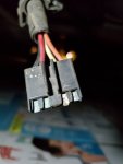
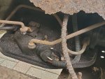
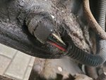
Once that is removed, the gates will not interfere with the transmission shift points. You will need to ”feel” each shit point and when the internal indents catch. Shift into park and test for continuity from a good ground to the black wire from the NSS (or voltage from the positive terminal to the black wire). Shift to neutral (after ensuring the wheels are chocked) and test again. If you don’t get continuity (or voltage) you have a ground issue. Either the NSS is bad (doubtful) or the ground path to the transmission is bad.
Sometimes just wiggling the shifter is enough to get the NSS working. I have to do that occasionally. And sometimes it does not like park, but will start fine in neutral.
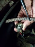
You can test continuity with your meter by using one of the white settings on the right (2000k Is a good one to start with). When testing continuity, you don’t want voltage, so always stay on one side of a circuit (negative to negative or positive to positive), never connect negative to positive. Most meters will beep or buzz when you have good continuity.
I would start by removing the interior shifter bezel. It should be floor mounted and look like this:
Removing the black bezel will reveal the shifter that looks similar to the part on the left.
Once that is removed, the gates will not interfere with the transmission shift points. You will need to ”feel” each shit point and when the internal indents catch. Shift into park and test for continuity from a good ground to the black wire from the NSS (or voltage from the positive terminal to the black wire). Shift to neutral (after ensuring the wheels are chocked) and test again. If you don’t get continuity (or voltage) you have a ground issue. Either the NSS is bad (doubtful) or the ground path to the transmission is bad.
Sometimes just wiggling the shifter is enough to get the NSS working. I have to do that occasionally. And sometimes it does not like park, but will start fine in neutral.
You can test continuity with your meter by using one of the white settings on the right (2000k Is a good one to start with). When testing continuity, you don’t want voltage, so always stay on one side of a circuit (negative to negative or positive to positive), never connect negative to positive. Most meters will beep or buzz when you have good continuity.

 )
)
 :rolleyes:")
")