• Notice for iPhone users: DO NOT use the image size reduction option when uploading photos to the forum. This causes portrait images to post as landscape. We have added a warning to the image insert pop-up as well.

Jeff's Offroad Build

I haven't forgotten about this thread, just waiting on several things:

Totally stainless to deliver all my hardware so I can start assembling some things. :D

Getting my frame back. I had a local jeeper repair some rough spots and re-enforce the rear spring hangers. When I get the frame back I will mount the axles so I can finish off the remaining tasks of upgrading the yokes, replacing the rear pinion seal, and installing the front lockouts. I also had to order a spring plate/u-bolt kit for the dana 60 since the old front axle was a dana 44.

Here are a few pics of my newest parts:

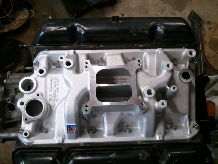
Edelbrock performer intake:
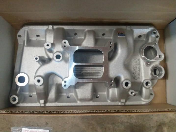
WP_000332-1.jpg


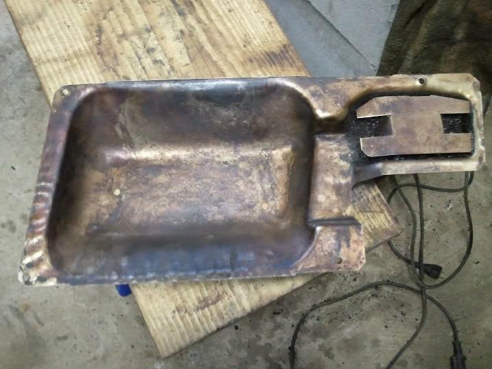
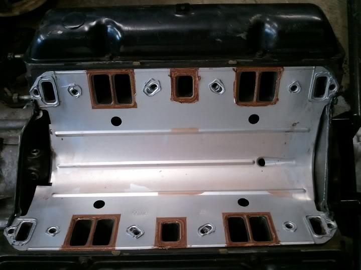
Stock intake heat shield cleaned up:
WP_000333-1.jpg


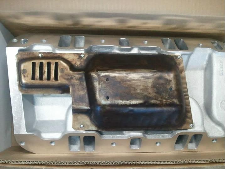
And installed on the new intake:
WP_000335-1.jpg


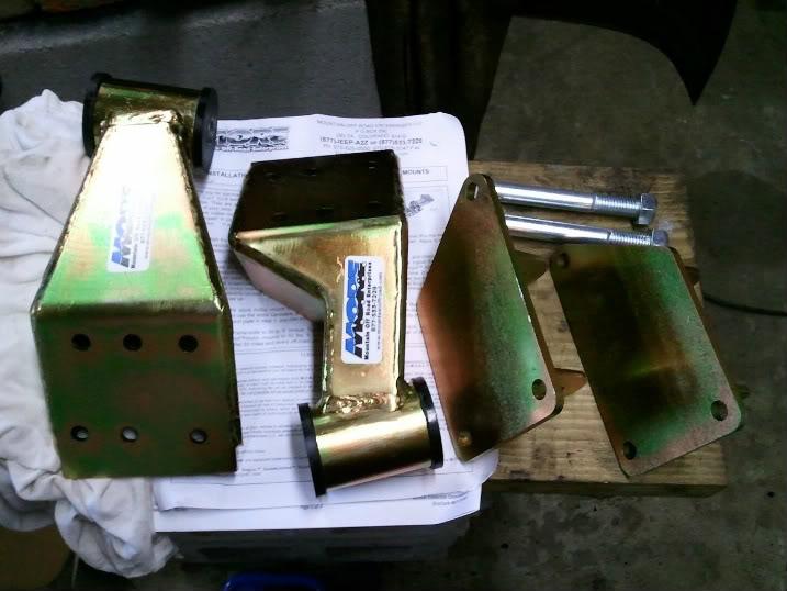
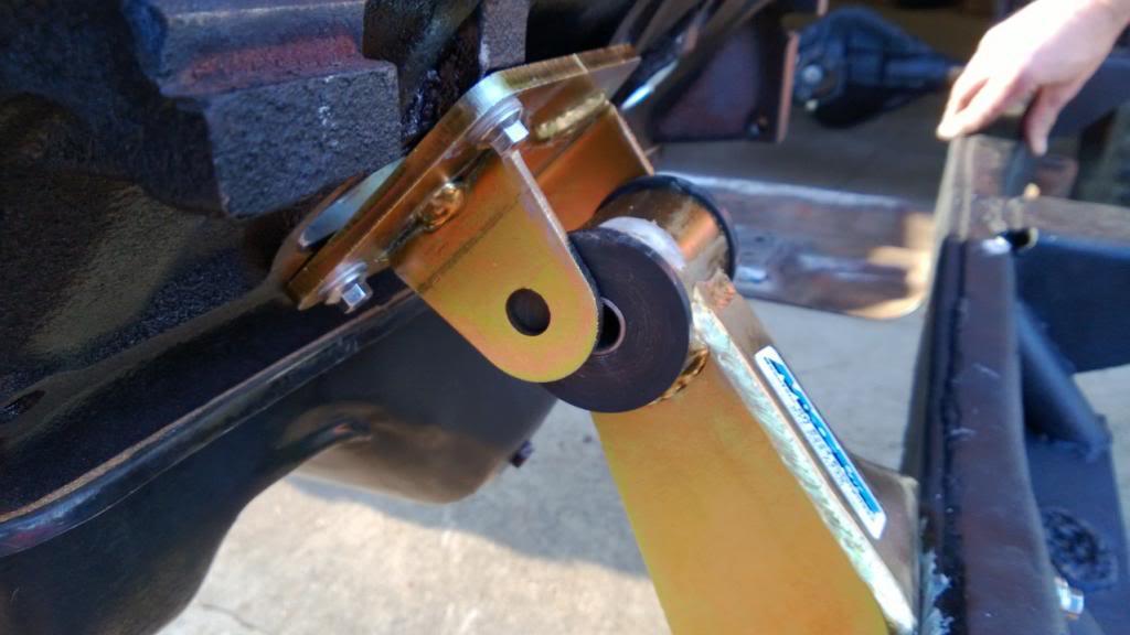
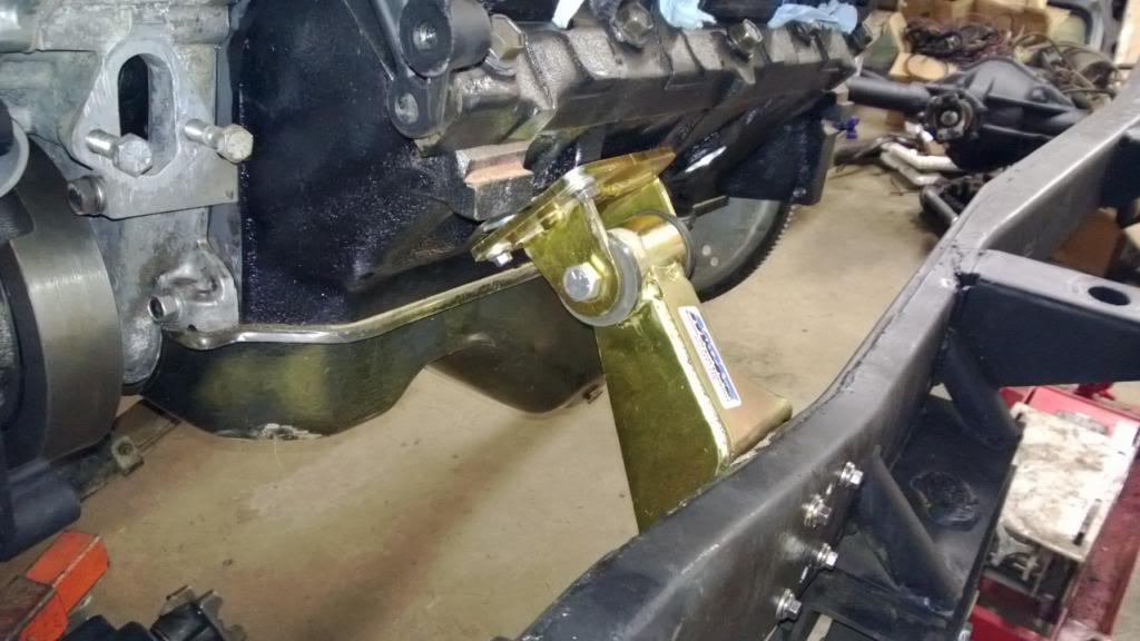
M.O.R.E. bomb proof motor mounts:
WP_000337-1.jpg


Expensive but hopefully worth it. :thumbsup:
 
updates

Received a couple more packages this week.

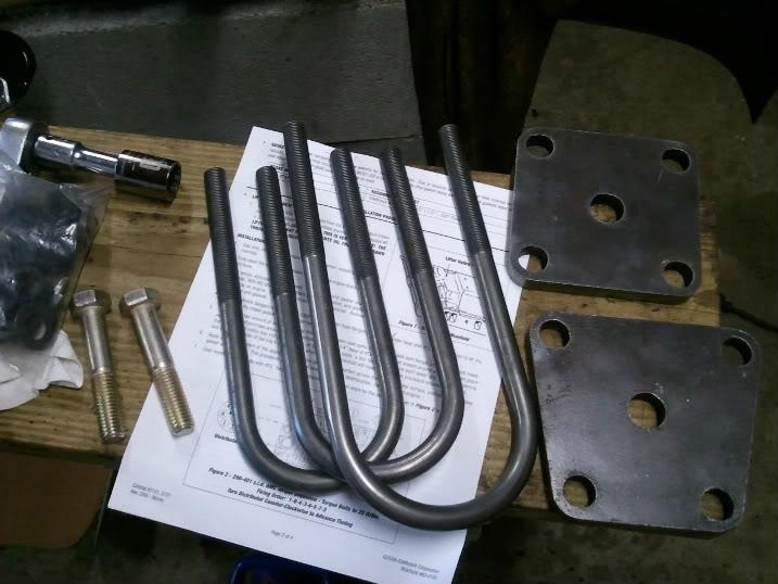
The new u-bolt kit for the dana 60 axle:
WP_000347-1.jpg


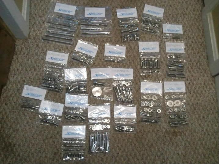
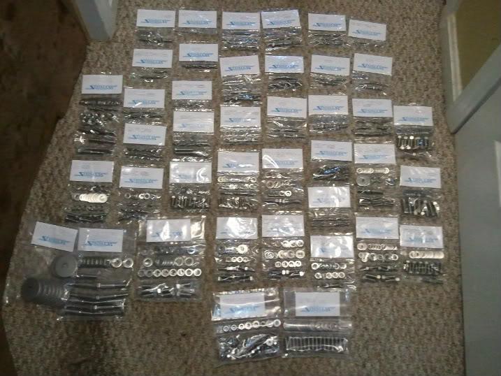
The totally stainless bolt kits:

Engine kits:
WP_000348-1.jpg


Body kits:
WP_000350-1.jpg


I don't know if I'll use all of these kits but it's nice having pretty much every bolt, nut, and screw labeled with it's application.

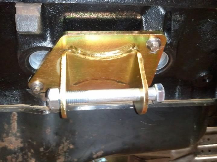
I installed the engine brackets for the motor mounts.

1) First I hand tightened two of the three bolts to hold the bracket in place.
2) Then I coated the third bolt with anti-seize and hand tightened it.
3) Next I removed the other two bolts one at a time to apply anti-seize and tighten them again.

Here's the finished installation:
WP_000352-1.jpg


Repeat for the other side and it's done.


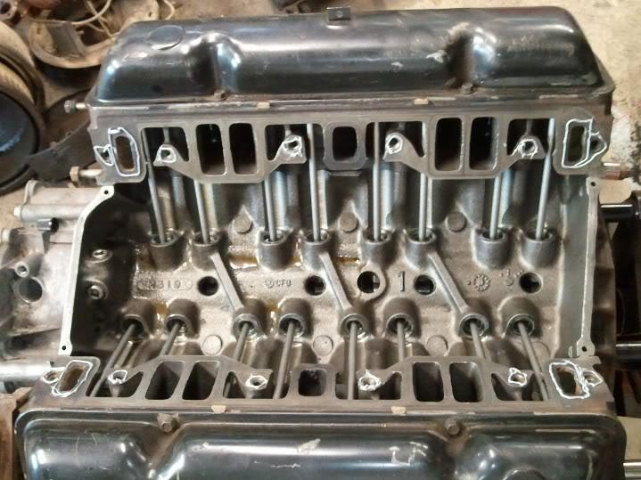
Got the new edelbrock performer intake installed. Here are the steps I took:

1) First I did a test fit without any gasket/sealants to measure the gap for the two end seals. I won't be using the rubber ones but ultra black instead.
2) Applied several coats of copper gasket spray to each of the intake ports on the metal valley pan gasket. Make sure to get both sides. I used lots of tape to catch the over spray around the water ports and bolt holes.
3) Applied ultra grey to each water port and bolt hole on the block.
4) Installed the valley pan gasket.
5) Applied ultra grey to the water ports and bolt holes on the valley pan gasket.
6) Applied ultra black for the end seals based on measurements in step 1.
7) Installed the intake manifold.
8) Applied anti-seize to the bolts since they were stainless steel and torqued them all to 20 ft-lbs.

Here are the pics I managed to get, not very many since this was a messy process:

Ready for the valley pan gasket install:
WP_000354-1.jpg


Ready for the intake install:
WP_000355-1.jpg


Intake installed:
WP_000356-1.jpg


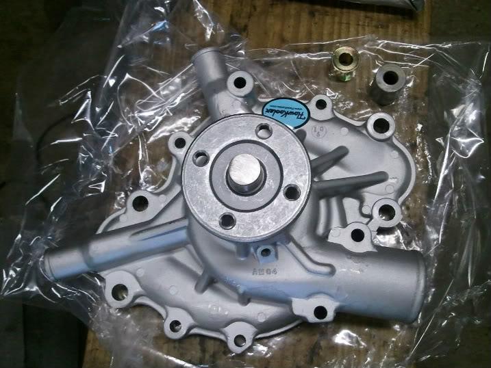
Received my new flowkooler water pump:
WP_000357-1.jpg


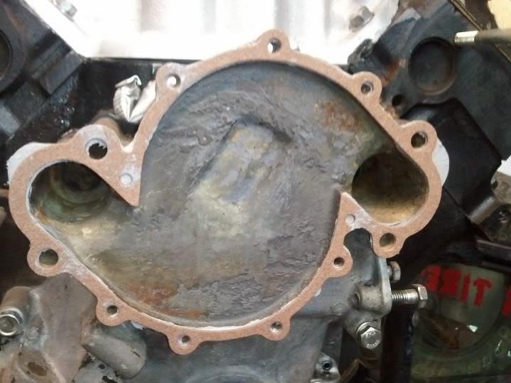
Applied some RTV to the timing cover mating surface and placed the gasket on:
WP_000358-1.jpg


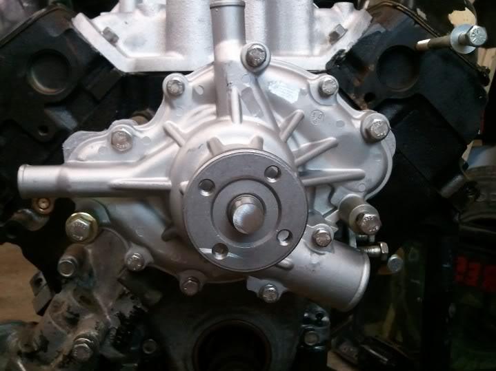
Applied more RTV to the gasket and placed the water pump on:
WP_000359-1.jpg


Used my stainless bolts with anti-seize. I left the four bigger bolts un-torqued until I bolt on all the other engine accessory brackets.
 
Are the engine mounting bolts stainless? I wouldn't use them anywhere there's a high-stress connection, they're weaker than grade 5 bolts. Fine for accessories and things, but not for frame/body bolting, engine mounts, suspension, etc. in my book. Just my :twocents:
 
The engine mount bolts are the high-strength stainless which I thought was equivalent to at least grade 5. I'll call totally stainless and see what they say. Thanks for the tip.
 
Cool, as long as they're something other than run-of-the-mill stainless bolts. Makes sense that they'd be on top of that if they're providing bolts specifically for engine mounting.
 
Many Moons ago, when I was in the Navy. They used a lot of stainless on minesweepers. I was told by an engineer at the Jacksonville Shipyards. The main reason for stainless failure was over torquing. Stretch a bolt and you're asking for failure.
 
So far I've been taking 20-25% less than the specified torque settings when using stainless steel bolts. For instance, on the intake bolts I torqued them to 20 ft-lbs instead of the 30 ft-lbs listed in the manual. I've also been coating all the threads with anti-seize.
 
more info on stainless bolts

I was looking closer at the stainless bolts and the engine mount bolts are actually ARP stainless bolts that should be grade 8. So I think totally stainless has provided the stronger bolts for the right application. I noticed the harmonic balancer bolt is also one of these ARP stainless bolts.

The body mount bolts were the other big ones I was concerned about but those appear to be standard 304 stainless which is less than grade 5. Should I get new, stronger bolts for the body mounts? :shrug:

I didn't get any suspension bolt kits in stainless form since I already have good grade 5 or 8 bolts.
 
I am using stainless in the body of my Postal. They are a pressure not in a shear application. Can't see where they would fail.
 
They're in both single shear and bending. I wouldn't use them.
 
It's been a while since I posted but it's car season so there's less time to work on the jeep!

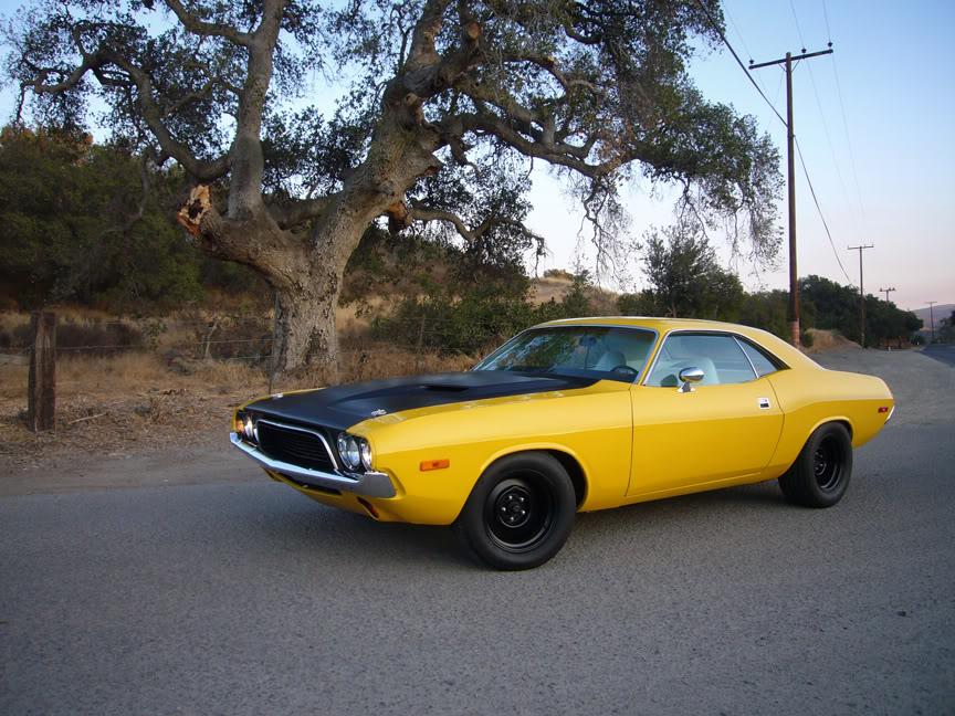
I found a good deal on a 1973 Challenger that I couldn't pass on:

ext2-1.jpg


It's only got a 318 small block but it's complete and ready for driving. I'll be making an RT clone out of it and probably returning it to the factory blue color. And dropping in a 440 big block with a six pack or dual quad carb setup. :cheers:

This will probably push my jeep completion date back a few months but I wanted to pick up a muscle car before the market fully recovered.


Back to the Scrambler.

For the last few weeks I've been sanding, priming, and painting parts so nothing much to document.

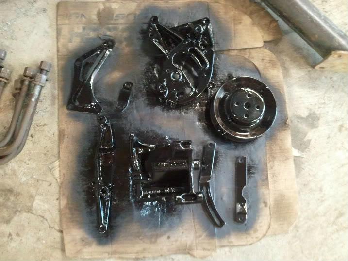
Engine accessories, some probably won't be used:
WP_000363-1.jpg


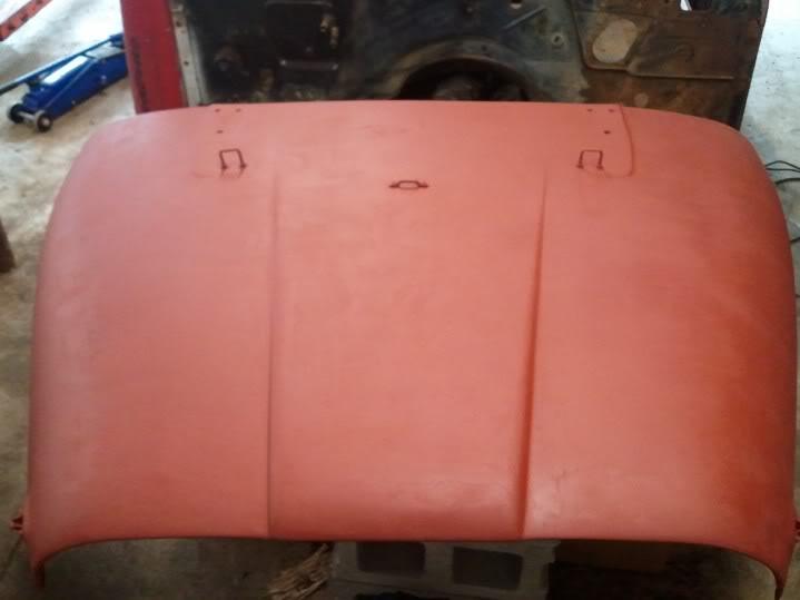
Hood in primer:
WP_000380-1.jpg


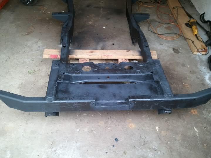
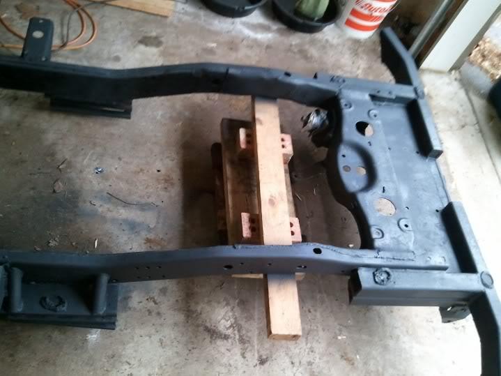
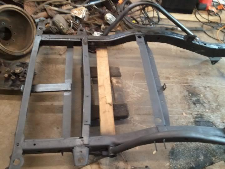
Frame in primer:
WP_000378-1.jpg


WP_000377-1.jpg


WP_000376-1.jpg


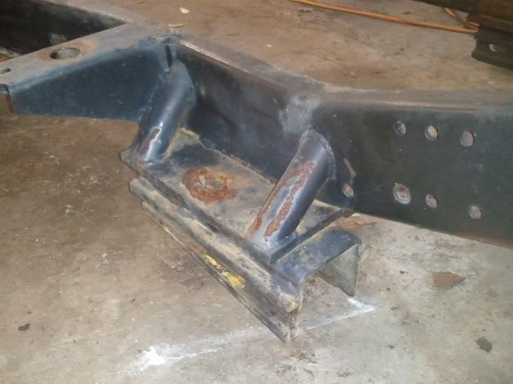
One thing I liked about this frame was the SOA setup. These are before primer and paint.

slider spring hanger:
WP_000371-1.jpg


I'd never heard of slider spring hangers but I'm going to try them out and see how they perform.

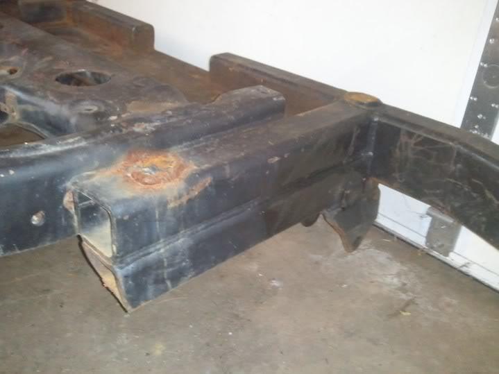
Out-boarded front hangers built in to the bumper:
WP_000372-1.jpg


Winch plate built in to the bumper:
WP_000375-1.jpg


.
 
Test fitted the rear axle today:

WP_000388-1.jpg


The bushings on the springs are good, I just need some center pins and one retainer bolt/sleeve for holding the leaf pack together. I think the shackles are 1 to 1.5 inch longer than stock but I couldn't find my stock CJ7 shackles to compare.

The old 14 bolt I had bolted right in but this one seems to be 1 inch too wide on each side. I'm guessing the PO had rewelded the spring perches or 14 bolts had different spring perch widths. I'll need to reweld the spring perches which is ok since I need to do the shock mounts anyway.


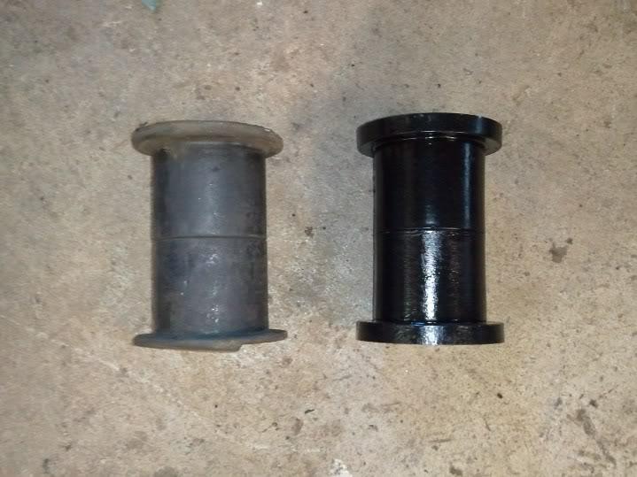
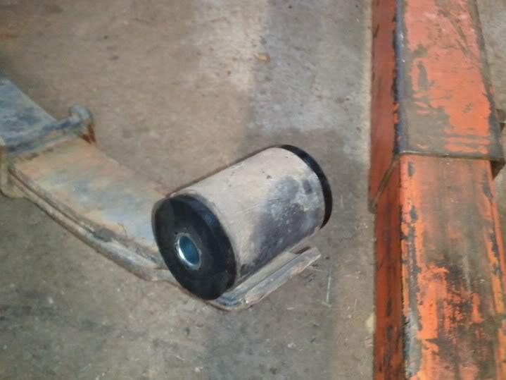
The front axle required a little more work. The bushings needed to be replaced so I pulled the new ones out of my Daystar master bushing set. The front springs I have are actually BDS 3.5 lift YJ springs so I had to use the rear bushings (the front CJ bushings are only 2 inches wide).

New bushing next to old:
WP_000390-1.jpg


Installed in the spring:
WP_000392-1.jpg


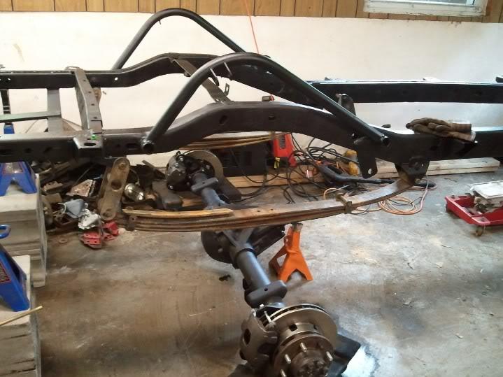
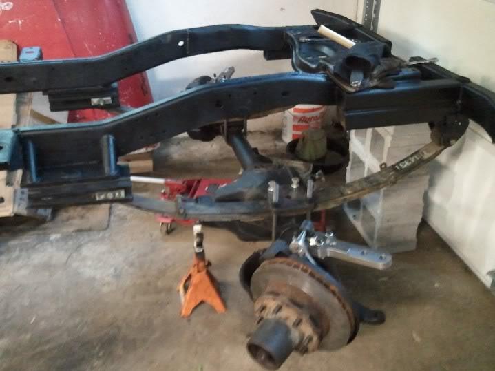
Springs and front axle installed:
WP_000398-1.jpg


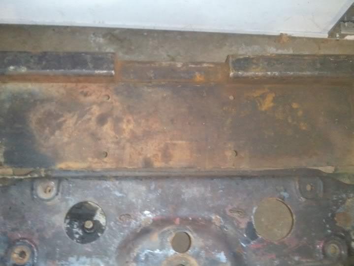
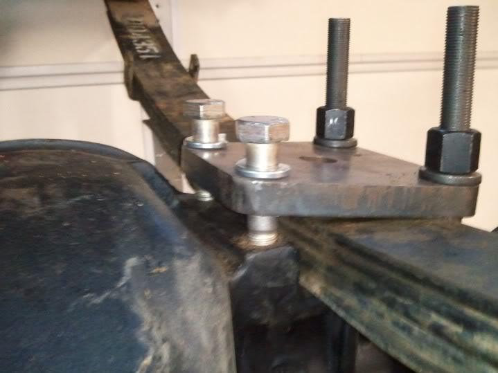
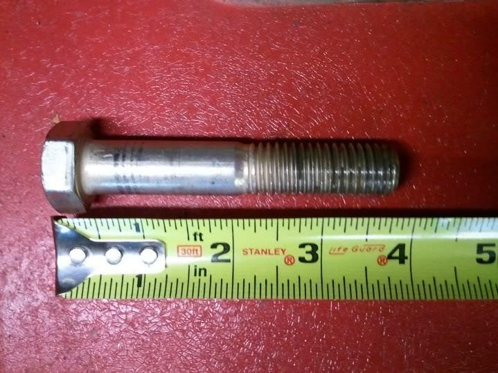
I ran into one small problem though. The spring plate kit I bought for the dana 60 seems to have the wrong size studs for the passenger side spring plate:
WP_000397-1.jpg


WP_000396-1.jpg


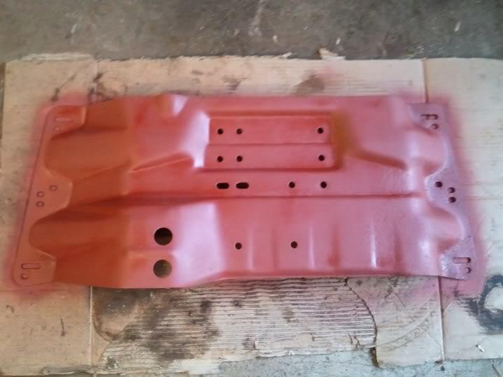
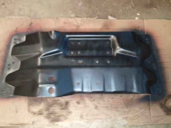
I also primed and painted the t-case skidplate/crossmember:
WP_000399-1.jpg


WP_000402-1.jpg


Since I'll be using an atlas t-case I'll probably end up creating a custom skidplate that doesn't hang as low.

.
 
Last edited:
Nice score on the Challenger! I had a '73 with the 318 and 727 auto. Was a fun car, wish I still had it!
 
I don't have any new pics yet since the chassis is still at the shop but I did order some new parts. :D Once we got the new yokes installed there was a lot of slop in the yoke so I decided to go ahead and rebuild it all and get new gears and lockers while in there.

USA Standard 5.38 thick gears for the 14 bolt
New carrier for the thick gears (reusing the detroit locker though)
Yukon master overhaul kit

USA Standard 5.38 gears for the dana 60
Yukon master overhaul kit
ARB air locker


I was initially planning on running with the 4.56 gears for awhile but they really needed to be overhauled. That pretty much blew through my Atlas savings, time to ask for a raise :rotfl:
 
Long time since last update

Hey guys, it has been a while since I posted so here's an update for anyone interested. I got the frame and axles back with the 5.38 gears and ARB locker in the Dana 60. I figured mounting the drivetrain would be my next task.

I've had my rebuilt AMC 360 sitting on the engine stand for over a year so I wanted to finally get it mounted. Round 1:


WP_20121121_003_zps4281f677-1.jpg


We had the passenger mount bolted up but the driver side was a little off???

After consulting the local 4x4 shop, it turns out the CJ frames tend to expand when no engine is mounted. All we had to do was use a come-along and squeeze the frame a little bit to get the mount lined up. Round 2:

WP_20130111_005_zps0043989e-1.jpg


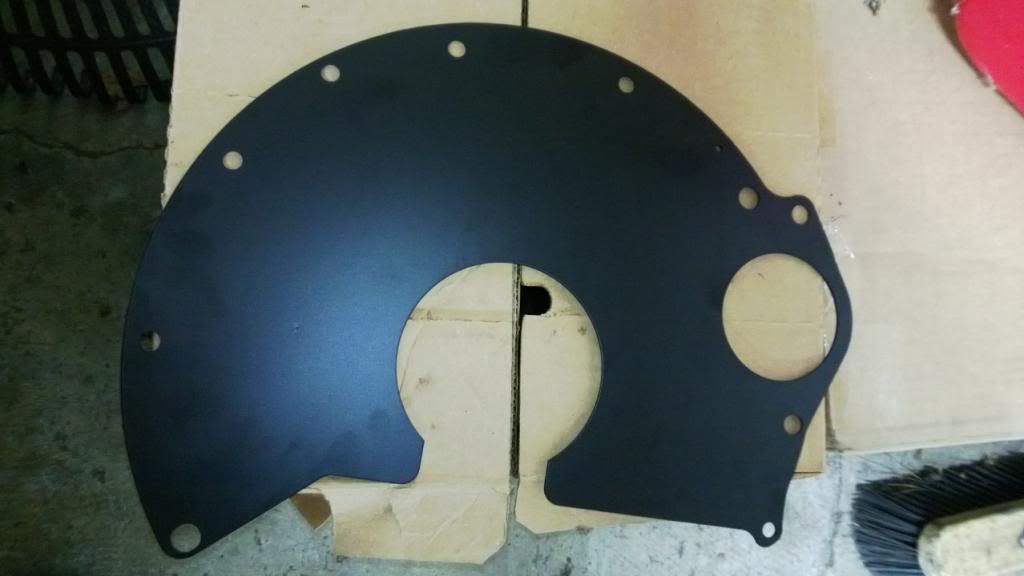
Before I could work on the transmission mounting I had to get some replacement parts:

WP_20130111_001_zps3e986422-1.jpg


WP_20130111_002_zps92dce384-1.jpg


WP_20130111_008_zps84914d2f-1.jpg


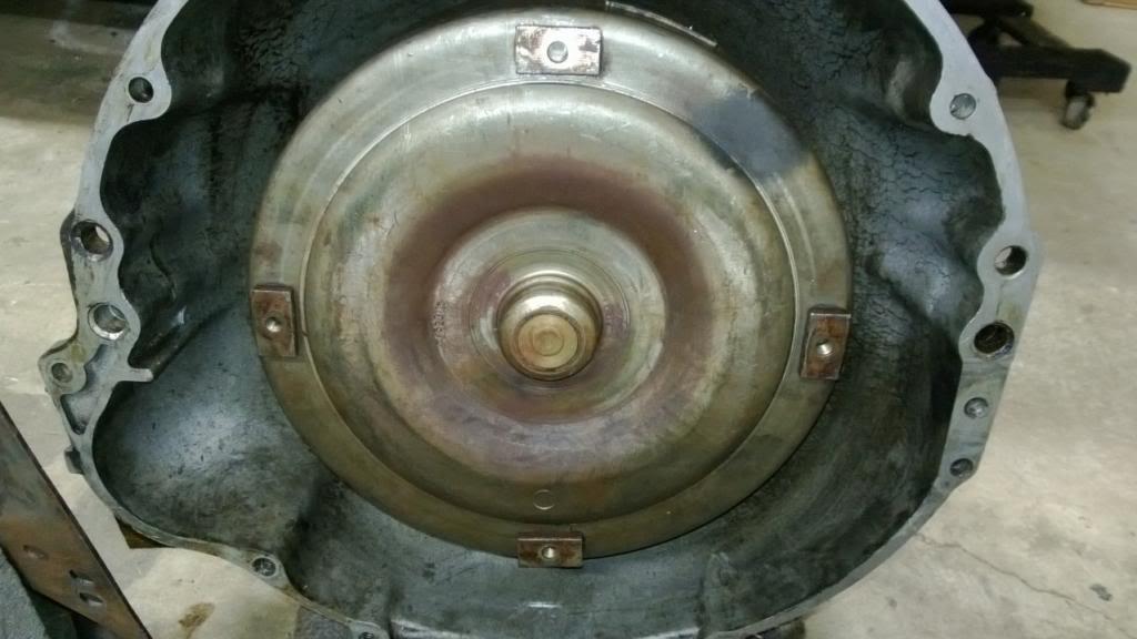
Next I drained the torque converter, refilled it with a quart of new fluid, and twisted it in place:

WP_20130111_004_zps68fdf8c3-1.jpg


I also bought a new transmission pan with a drain plug and replaced the filter, pan gasket, and front pump seal.


Here are a few pics of the transmission being mounted. I mostly followed the manual so nothing too exciting here:

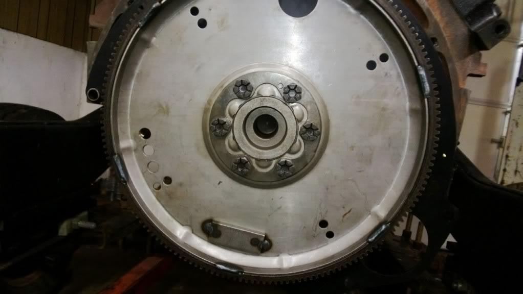
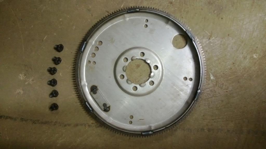
First step was mounting the flexplate on the crankshaft. The manual I have refers to the flexplate as the driveplate:

WP_20130117_001-1.jpg


The bolts were torqued to 105 ft-lbs in three stages, 35, 70, and 105. I also used red Loctite on the threads. Notice the reinforcing ring between the bolts and flexplate. From my research, this helps distribute the force applied to the bolts from the crankshaft which helps prevent flexplate damage.


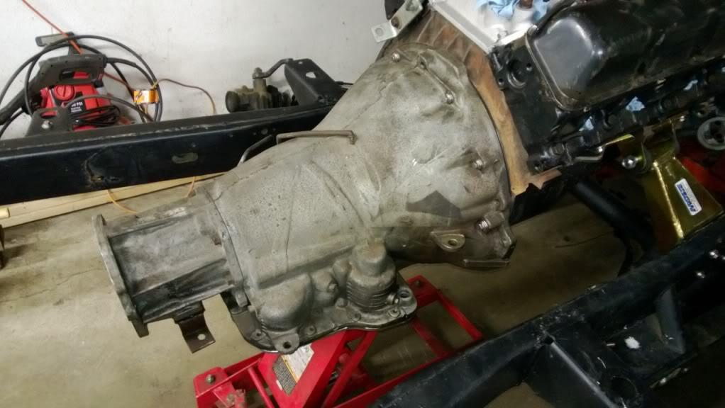
Next comes the actual transmission mounting, it took me a few tries to get it level since the transmission jack plate can be angled differently:

WP_20130117_002-1.jpg


Before mounting the transmission, I lined up the bolt hole I marked (stamped circle in the picture of the torque converter above) with the mark on the flexplate (the three holes on the flexplate). A lot of people mark with spray paint too. This greatly improves the next step because the torque convert to flexplate mounts only line up one way.

The manual lists the torque spec for the bellhousing to engine bolts at 28 ft-lbs.


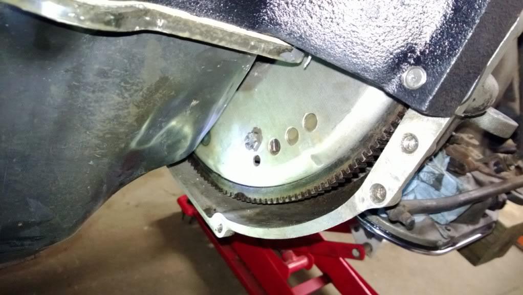
Bolting the flexplate to the torque converter:

WP_20130117_003-1.jpg


The thing to remember on this step is not to tighten the first few bolts because it will cause the last few to not line up correctly. After they are all hand-tightened, rotate around to each one to torque it down. My manual lists the torque spec as 22 ft-lbs.


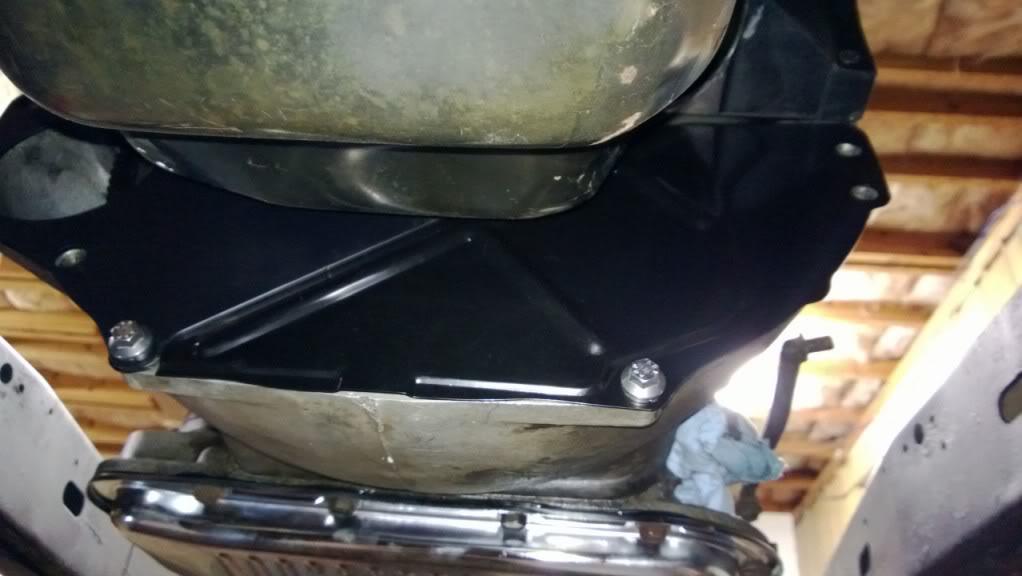
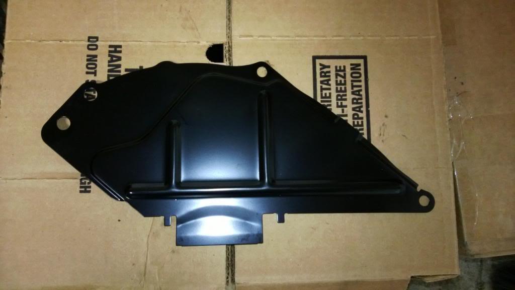
Now bolt on the inspection cover:

WP_20130117_004-1.jpg


My bolt kit only included two bolts for the inspection cover so I'll need to dig up some spares for the other two holes.


Later I will install the new shifter and cooler lines. The factory skidplate is not lining up properly with the holes in my frame but I'll probably just have a custom one made at a later time. For now I've got a chain holding up the backend of the transmission.

I also purchased an Atlas 4-speed transfer case that should arrive in the next couple weeks!

I will also purchase custom drive shafts when the t-case arrives to complete the drivetrain. Next will be brake lines, fuel lines, gas tank, and engine/tranny accessories as time and money permits!
 
a few new pics

The Atlas t-case is still a couple weeks out so I've been trying to decide what to do next. Originally I was going to work on brake and fuel lines since I have the body off. However, I decided to just let the shop fab up all the lines since the axles are not OEM and I did the rear disc brake conversion. They will want the body mounted so they can setup the new master cylinder. They will also need the body mounted to set the rear pinion angle later on.

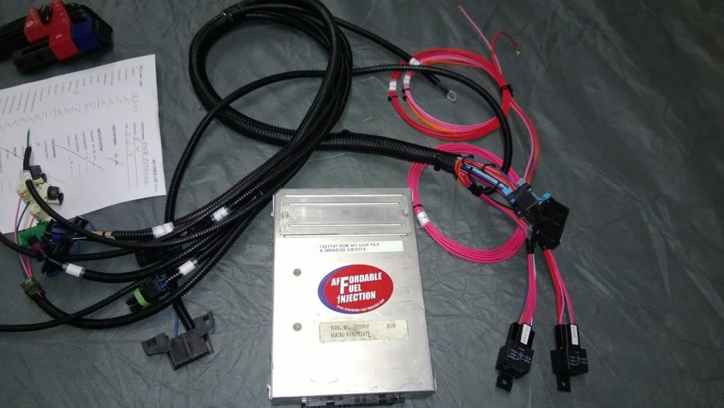
So my immediate plans are to paint and mount the gas tank, mount engine accessories, and then mount the body. I had some money saved up from the holidays so I went a bit of a spending spree! New purchases: Lokar automatic shifter, transmission cooler lines, radiator and hoses, fuel injection kit. The transmission cooler lines were ordered from inline tube which I recommend for any OEM line replacements. The radiator is just an OEM replacement from AutoZone. The fuel injection kit is from Affordable Fuel Injection. It's a cheaper than most other kits so I'm hoping it works out ok. One thing I really like about it is the computer controlled distributor.
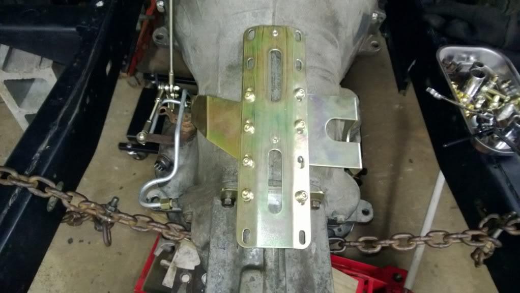
The Lokar shifter was not cheap but I really like the quality and the fact that it doesn't use cables. Here are some pics of the install:

The instructions say to attach the three brackets to the main plate first, but I found it easier to install the brackets on the tranny and then attach the main plate.

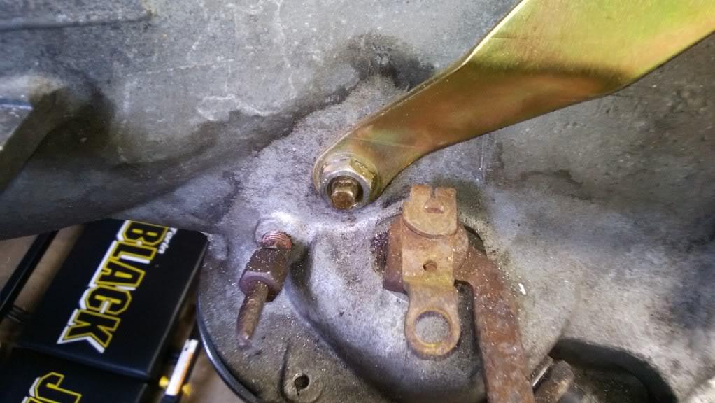
The driver side bracket attaches to the front band adjuster, secured by the lockout nut:
WP_20130127_003_zps5884f5a4-1.jpg


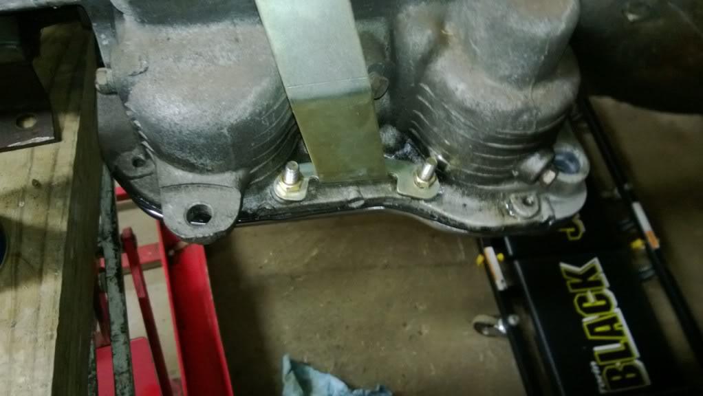
The passenger side bracket attaches to two bolts (supplied by the kit) that go through the tranny pan:
WP_20130126_009_zpsd36fff41-1.jpg


I found it very helpful to use lubricant, WD-40 or Liquid Wrench, etc... on these two bolts because the normal tranny pan bolts don't thread all the way through like these do.


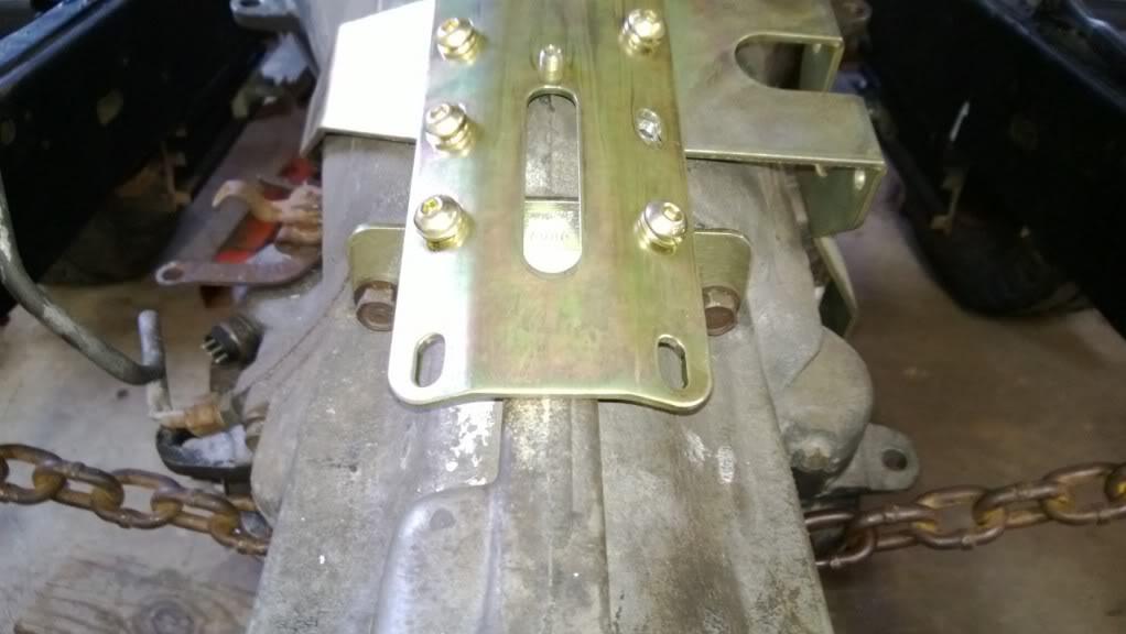
The rear bracket attaches to the tail housing. I didn't get a picture of this but I had to grind the case a little to get the bracket to fit. Here is the main plate attached to all three brackets:
WP_20130127_002_zpsf1cea365-1.jpg


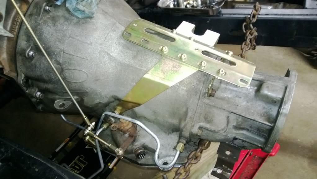
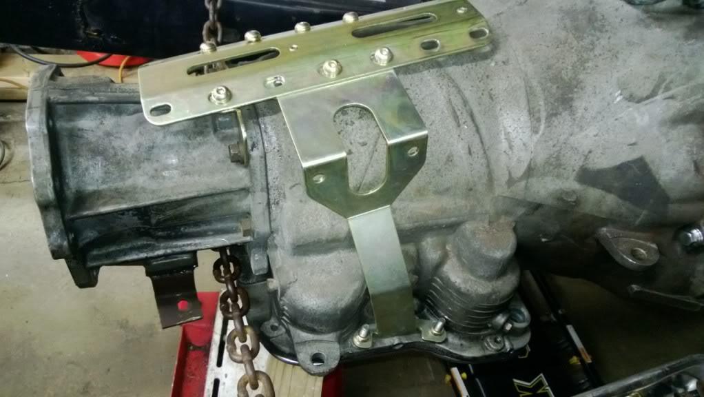
Here are some shots of the main plate installed:
WP_20130201_002_zps06301367-1.jpg


WP_20130201_004_zps6c013e95-1.jpg


WP_20130201_001_zps0b9a3183-1.jpg


I have the kit's linkage arm installed as seen in the pics above but I have yet to finish installing everything since I want to get the body on to make sure the shifter arm doesn't hit anything. I'll post the finished product when I get it done.
 
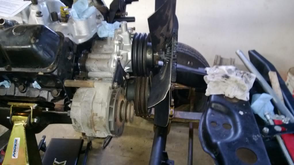
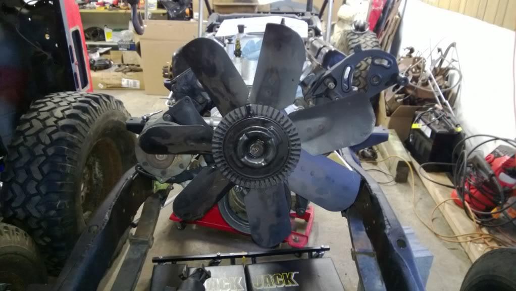
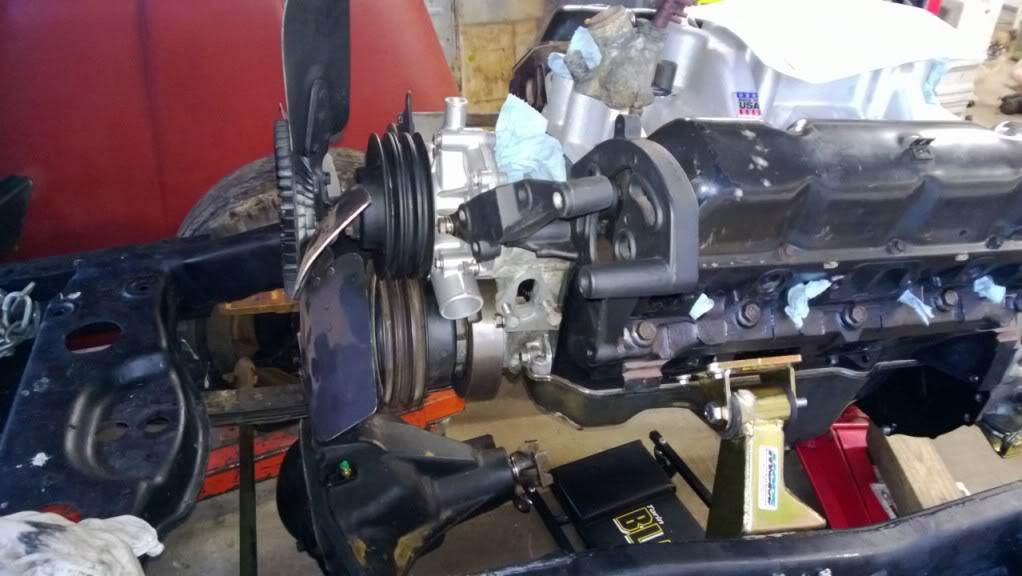
I also installed the crank pulley, water pump pulley, and fan.

WP_20130202_004_zps544532f8-1.jpg


WP_20130202_005_zpsc63ef217-1.jpg


WP_20130202_006_zps948772c4-1.jpg


The alternator and power steering pump brackets are not tightened yet since I need to pickup new belts and get the power steering pump cleaned up and installed.
 
New parts!

Got home from work today and found some boxes of new parts waiting! I'm planning on mounting the body and grill tomorrow so I'm hoping to make some good progress in the next few weeks.

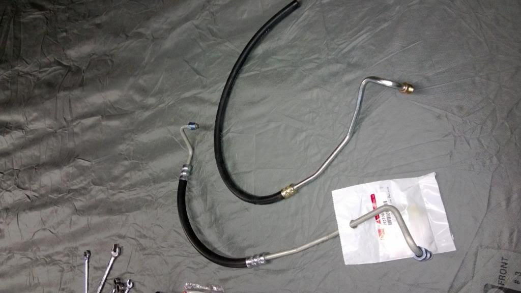
New items: power steering lines:

0659fe1f9d22457fb24e352911a56cc7_zps72ad-1.jpg


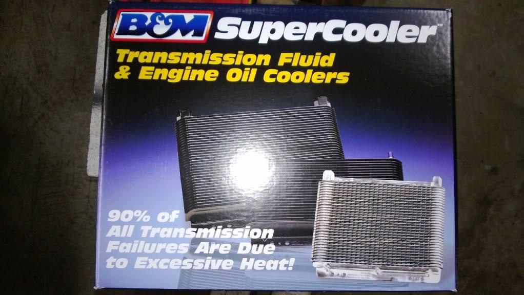
Transmission cooler to help out with the life of the auto tranny:

WP_20130208_002_zpsc4e965ec-1.jpg


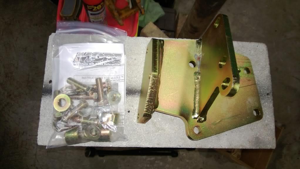
HD steering box bracket from M.O.R.E.:

WP_20130208_003_zpsc0b44ede-1.jpg


I really like the M.O.R.E. engine mounts so I figured this would be another good item to have. Their stuff isn't cheap but it is very good quality.


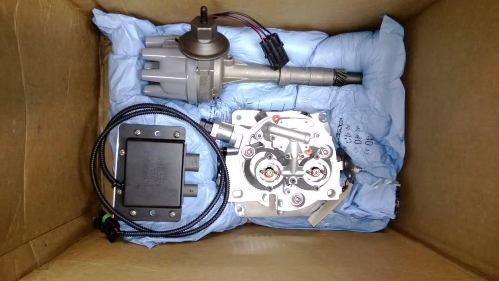
And the new Affordable Fuel Injection kit:
WP_20130208_004_zps0a84974e-1.jpg


WP_20130208_005_zpsb8754075-1.jpg


There is another small box with some of the sensors, fuel filter, electric fuel pump, and cd with installation documentation. I'm really looking forward to getting this installed. :thumbsup:
 
shock towers

I decided to do the Ford F-250 shock tower conversion since it supposedly is a quick way to gain some extra shock travel.

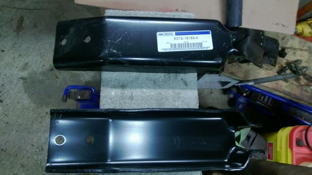
Here are the two shock towers, about $12 a piece from Ford:
WP_20130215_003_zpsc5da4343-1.jpg


The pic shows the part number if anyone needs it: E5TZ-18183-A.


I fitted the Ford tower into the stock location. If you are running stock axles you may have to move the tower but the dana 60 axle I'm I using lines up nicely.

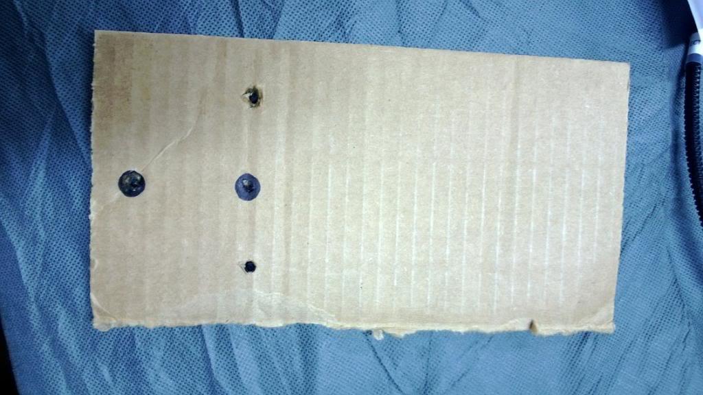
First step was to make a template to mark the location for drilling new holes:
WP_20130215_004_zpsf688293b-1.jpg


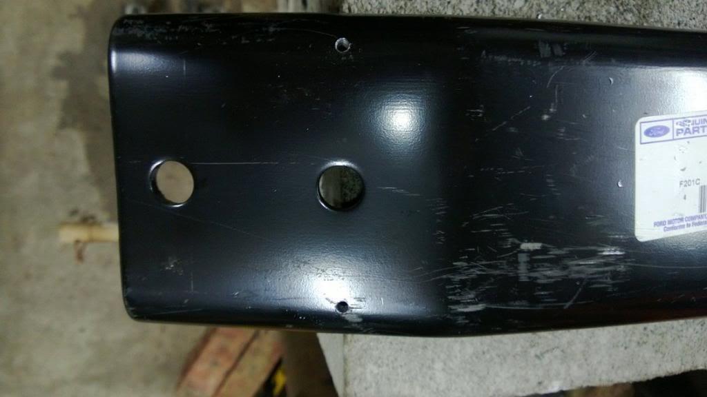
Then I marked the tower and started drilling:
WP_20130215_005_zps5f7c6d49-1.jpg


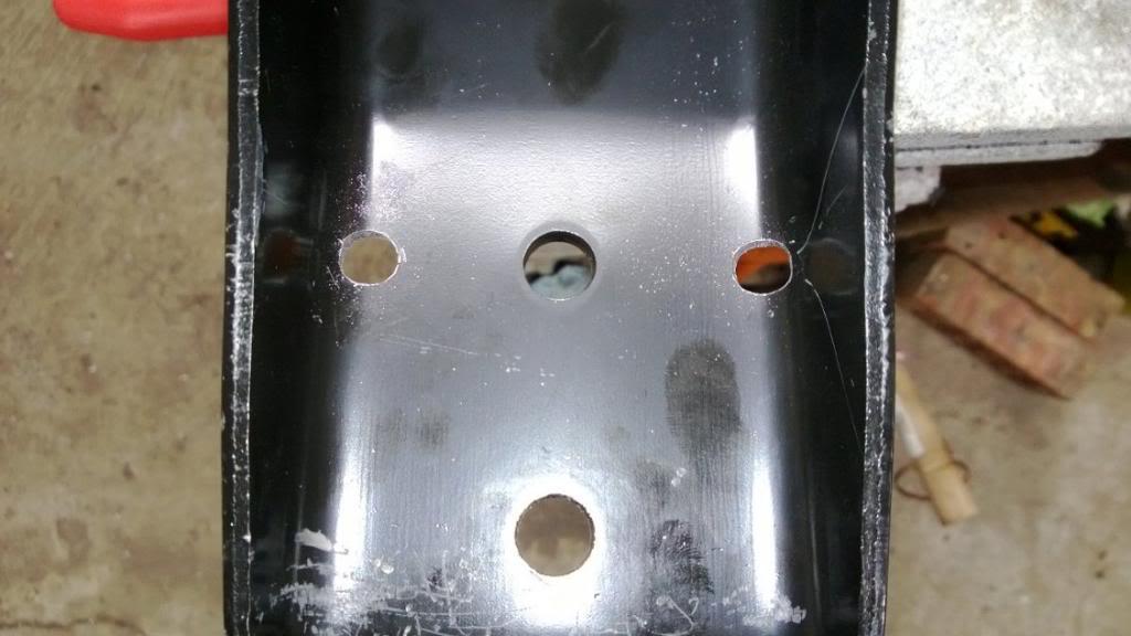
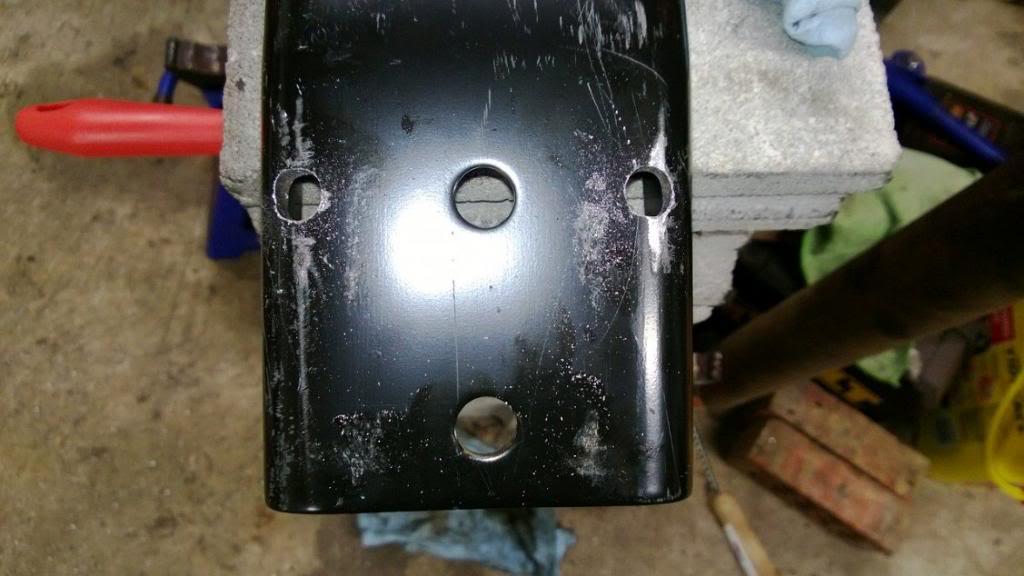
As I suspected from the measurements, and starting to become apparent when I was drilling, the new holes were going to end up a little on the curved part of the tower.

Here are the finished holes, 3/8 in size:

WP_20130216_006_zpsfe196dc6-1.jpg


WP_20130216_005_zps3b444b19-1.jpg


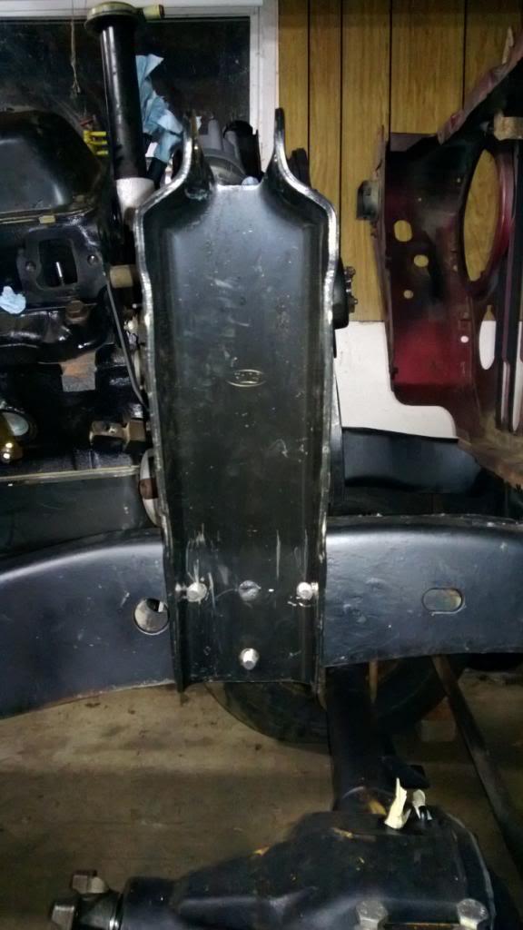
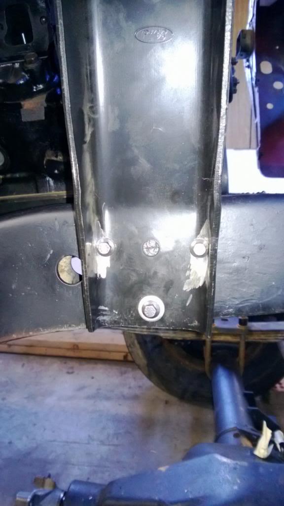
A little grinding and I ended up with plenty of space to fit the bolts and ratchet with socket:

WP_20130216_007_zpsc3355eb6-1.jpg


WP_20130217_001_zps7766e53b-1.jpg


Normally I'm not a big fan of the 3/8 head on these ARP stainless bolts but in this case it was helpful. :)

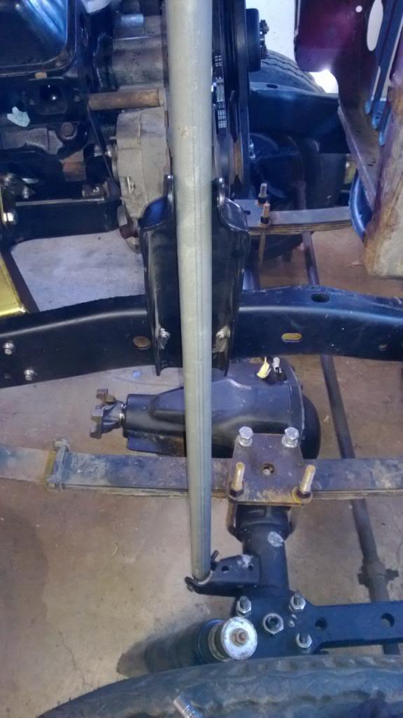
Here's a pic with a pipe where the shock would go since I didn't have a shock long enough to fit:

WP_20130217_002_zpsfafbf3d2-1.jpg


In the bottom of the above pic you can see I had an old shock from my 2008 JK but it was too short!

It's about 28 inches from stud to stud so hopefully I'll get some good shock travel. All-in-all for about $25 I can't complain too much. :)
 
My Atlas II transfer case has arrived at the shop but they are pretty busy right now so I'm waiting to get the Scrambler in. I could install it on my own but I need them to set the pinion angle on the rear axle and weld up the spring perches.

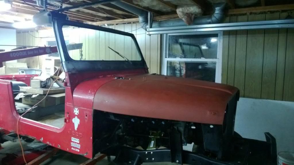
Here is a new pic with windshield and hood installed:

WP_20130301_003_zps4ac13e53-1.jpg


The hood is still in primer until I decide what to paint it. I also installed the throttle body to prepare for fuel lines.

I ordered some Metalcloak flat fenders since I cannot use the YJ fenders with the CJ grill and hood.

I pulled out the wire harness from the 86 CJ7 I had parted out and realized it was in pretty bad shape so I ordered the Painless P/N 10110 harness

I also ordered a Vanco hydroboost system since I need upgrade to power brakes.

I'll be posting walkthroughs of the installs when everything arrives. :thumbsup:
 
Back
Top