FLCJ8
Legacy Registered User
- City
- Palm Bay
- State
- FL
Randy what is the purpose of the crossover pipe when each side goes out the back ?
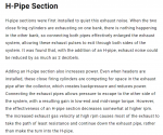


Randy what is the purpose of the crossover pipe when each side goes out the back ?

Randy what is the purpose of the crossover pipe when each side goes out the back ?

 The equalize part I can fathom
Thanks for the response. I would like to see it played out with some clear pipes and maybe some special blue smoke coming out the right bank and a light yellow out the left and see this really happen. Seeing is really believing


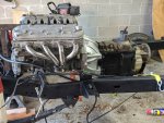
It's an early Dodge nv4500. IRrebuilt with a GM 10 spline input shaft, bearing retainer, and hydraulic throw out. The Dana 300 bolts right up to the Dodge NV 4500 no adapter required.Brentox,
What are you planning to use for the nv4500 to d300? I decided on using the np241c due to the adaptation issues, was just easier. Also allows the jeep to be flat towed for longer distances.
Measuring from the front edge of the frame to the front part of the frame mount, I’m sitting at 30 inches. I attached a couple of pics so you could verify points of reference. Once I was happy I drilled through the mounts in the forward stock bolt holes and ran a couple of bolts through. I’ll finish weld the mounts once the engine is back out. I ended up 1” to the drivers side. I wanted as much driveshaft to pan clearance as possible. I had to modify the drivers side mount bracket a bit to accommodate this position. (welded the slot shut and drilled where needed.) My engine also sat 3/8 low on the drivers side so I fixed that too while I was drilling the new hole. I leveled the trans pan so there is a 5* downward tilt to the whole powertrain. That’s how I’ve always done it and the 5* angle really helps with the rear C/V shaft angles.Hey Randy I've been working on the body for awhile, but now back on drive train. Using Dave's motor mounts as well. Got the 5.3/NV4500 stabbed into place and will be using a Dana 300 xfer case. With "C" clamps I'm biased 13/16th to the drivers side and level front to back. It looks like my mounts are on the frame close to same location as yours. Have you set your final location on mounts yet? If so would you mind sharing where you ended up? Just wanting to see if I'm close or way off. Thanks, Brent.
View attachment 80548
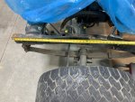 Looking at your pic Brentox, your engine looks a bit further back than mine. Might just be the angle. I use the front edge of the body mount brackets as my limit line, that’s right about where the firewall falls. So I try to be a bit shy of that. I usually like at least an inch between the back of the heads and the firewall.
Thanks so much Randy. I am sitting further back than I would like. Did the first attempt when I didn't have the body on hand to transfer measurements. Now I've got it all back but work got in the way this weekend. Thanks for the 5* info as well. I did think level was optimal, but I thought I'd start there and tune it up. Thanks again for sharing your knowledge.Measuring from the front edge of the frame to the front part of the frame mount, I’m sitting at 30 inches. I attached a couple of pics so you could verify points of reference. Once I was happy I drilled through the mounts in the forward stock bolt holes and ran a couple of bolts through. I’ll finish weld the mounts once the engine is back out. I ended up 1” to the drivers side. I wanted as much driveshaft to pan clearance as possible. I had to modify the drivers side mount bracket a bit to accommodate this position. (welded the slot shut and drilled where needed.) My engine also sat 3/8 low on the drivers side so I fixed that too while I was drilling the new hole. I leveled the trans pan so there is a 5* downward tilt to the whole powertrain. That’s how I’ve always done it and the 5* angle really helps with the rear C/V shaft angles.View attachment 80577View attachment 80578Looking at your pic Brentox, your engine looks a bit further back than mine. Might just be the angle. I use the front edge of the body mount brackets as my limit line, that’s right about where the firewall falls. So I try to be a bit shy of that. I usually like at least an inch between the back of the heads and the firewall.
No problem. Glad to help. I dug through the "archives" (Dang Photobucket) and found a pic of where the engine was sitting in my Copper build. This is the best shot I could find, but I had it even further forward. I think you can see the body mount bracket in relation to the firewall in this pic.Thanks so much Randy. I am sitting further back than I would like. Did the first attempt when I didn't have the body on hand to transfer measurements. Now I've got it all back but work got in the way this weekend. Thanks for the 5* info as well. I did think level was optimal, but I thought I'd start there and tune it up. Thanks again for sharing your knowledge.
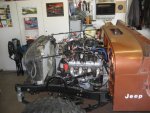
Zoom in- the Bellhouding /block seam is actually just behind or right in line with the spring rear bolt. (I had to do a outboard to fit the axle width). On my current build with the Dave’s mount it looks to be a couple inches in front of the body mount. About 1” behind the spring rear bolt. It’s hard to get things placed correctly with the body off. I remember on Copper I had the body on and off a couple times and ended up shifting the engine to accommodate the fan clutch. But the pic shows the final placement and I had about 1 inch between the fan clutch and the radiator. Here’s a pic currently looking straight down on the pass side- I can take a pic with a straight edge after work to confirmThat,s a great pic. Looks like bell-housing/block are almost in line with that body mount. Really appreciate you sharing the knowledge you have amassed.
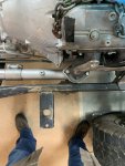
That helps a bunch. I really do appreciate it. Don't mean to be a pain in the A$$.Zoom in- the Bellhouding /block seam is actually just behind or right in line with the spring rear bolt. (I had to do a outboard to fit the axle width). On my current build with the Dave’s mount it looks to be a couple inches in front of the body mount. About 1” behind the spring rear bolt. It’s hard to get things placed correctly with the body off. I remember on Copper I had the body on and off a couple times and ended up shifting the engine to accommodate the fan clutch. But the pic shows the final placement and I had about 1 inch between the fan clutch and the radiator. Here’s a pic currently looking straight down on the pass side- I can take a pic with a straight edge after work to confirm View attachment 80591
That helps a bunch. I really do appreciate it. Don't mean to be a pain in the A$$.
I just don't want to come off like I'm not willing to put in my own work. Hopefully I can return the favor.Please, ask lots of questions! It not only helps you, but all of the others doing a similar swap.
No problem. I enjoy being able to help others out. That’s part of what makes documenting my builds so fulfilling. To be honest, I wish I lived somewhere closer to other Scrambler owners so that we could help each other in our builds.That helps a bunch. I really do appreciate it. Don't mean to be a pain in the A$$.
That's what I'll setup this weekend. Then set the 5* up. I'm trying to avoid any body lift as well. Thanks again for the awesome pics.No problem. I enjoy being able to help others out. That’s part of what makes documenting my builds so fulfilling. To be honest, I wish I lived somewhere closer to other Scrambler owners so that we could help each other in our builds.
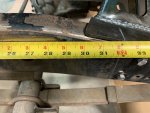
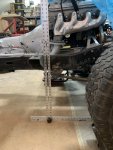
I went out and took another picture with a straight edge. With the mounts in the position I told you in the first post, the back of the engine is 2” in front of the body mount bracket. (The straight edge in the picture is 2” wide. ) That places the back of the block 1 1/2” back of the spring hanger bolt. You should have a little under 2” firewall clearance on the passenger side with this placement. This is with the 5* tilt factored in. I’m thinking that the tilt might not matter as much with a manual trans but I’m worried about tunnel to trans clearance as is. I really don’t want a body lift...
Please ask if you have any more questions.View attachment 80598