• Notice for iPhone users: DO NOT use the image size reduction option when uploading photos to the forum. This causes portrait images to post as landscape. We have added a warning to the image insert pop-up as well.

spankrjs's Biloxi, MS '83 Scrambler

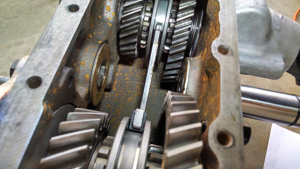
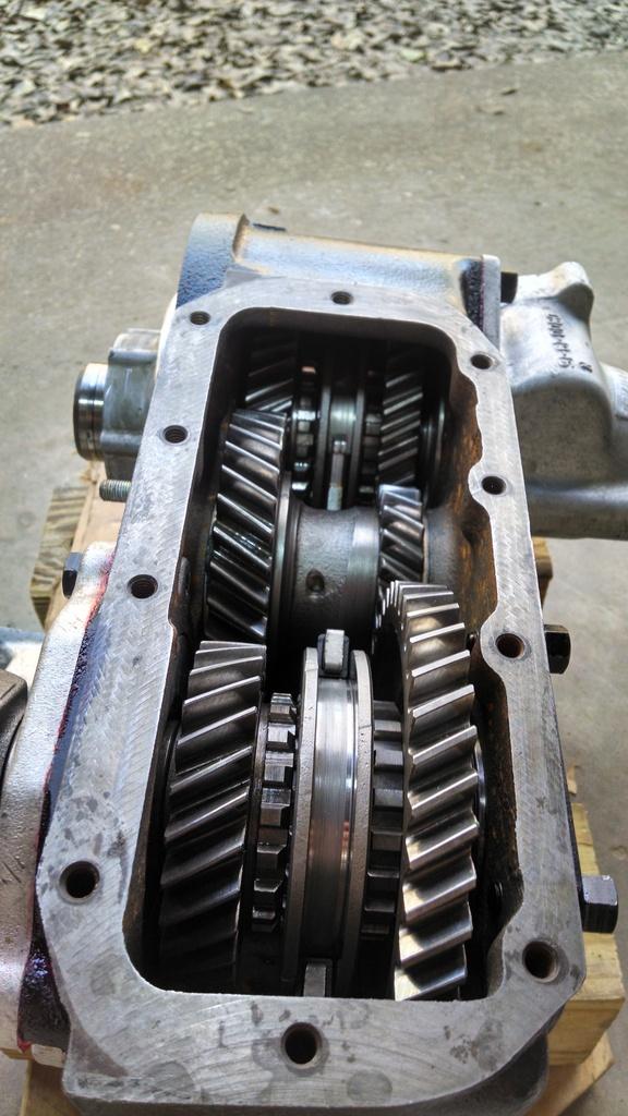
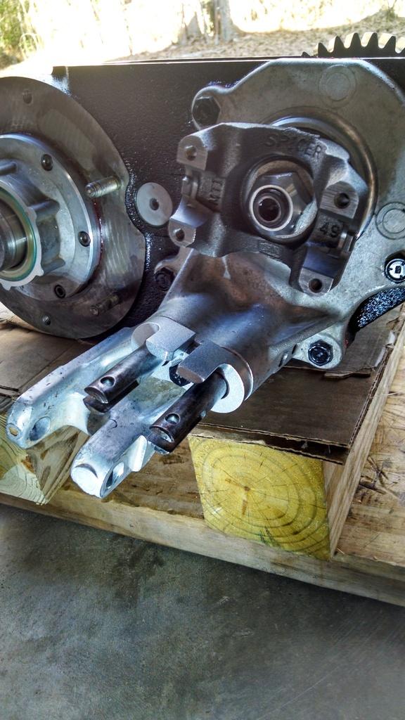
Do you have any pictures about how the shift rod actually plugs in to the transmission?

Not really :shrug:

Once you get the top cover bolted on to the main transmission body, the shifter rod is sticking out the back end of the top housing. There is a hole in the rear case where this rod simply slides through.

IIRC, the rod sticks out of the top cover a certain distance when everything is in neutral. The transmission has to be in neutral for the shifter block spring loaded ball thingy to be installed. If its in neutral, everything slides together pretty easily.

It is hard to explain, I recommend doing a few dry runs before applying sealant :thumbsup:
 
What oil are you going to use in T5 ?

Ah yes, I knew someone would ask this "loaded" question :crazy: :thumbsup:

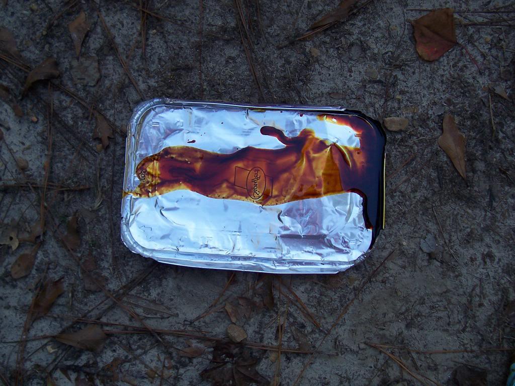
When I first embarked on my T5 journeys, I read a whole bunch of stuff/information/crap about what type of fluid to use. What I have seen, come out of actual, original, low mileage AMC Jeeps is this stuff:

0018-1.jpg


I have seen this same fluid come out of T5's, T176's, and Dana 300's. I am almost 100% positive that this is the actual AMC Part #8983 000 000 fluid everyone talks about. It has a unique "smell", and it stains anything it come in contact with.

Now, everyone can agree that ATF belongs in WORLD CLASS T5's because of their unique synchronizer assemblies. A NON World Class T5 is built more like a T176, brass blocking rings and deep oil flutes machined in the shafts/gears for lubrication.

So, with this in mind, I sent a sample of this AMC 8983 000 000 fluid to a lab, this is what they said:

IMAG2404_zpsb4847f07-1.jpg


It would appear to me that the "original AMC" fluid is more like a gear oil. That would make since, especially since they used the same stuff in Dana 300's. What is interesting, they DO NOT use this fluid in axles. So, this would lead me to believe that it is some type of early "Maunal Transmission Lubricant", a bit different then the gear oils of the day, and obviously "yellow metal safe".

The FSM's of various years say one thing, the owner's manuals of various years will say another thing, but once you research enough it comes down to:

1) 80/90 weight gear oil is "OK" for Top Off ONLY
2) AMC 8983 000 000 is for drain/refill

Page #5 from the "official" Borg Warner AMC t5 Manual states to use only the 8983 000 000:

https://www.scribd.com/doc/23066609/T4-T5-AMC-Trans-Rebuild-Manual

The '82 FSM does mention Dextron II, BUT this was superseded by a NHTSA Recall:

http://www.jeepforum.com/forum/f8/dang-t-4-transmission-fluid-980897/


What is really interesting about that recall, to me anyway: Both catastrophic T5 failures I had both occured while in 5th gear, no prior symptoms, AND running ATF. Coincidence :shrug: That last bit of the recall note, and I quote:
CONSEQUENCES OF DEFECT: IN EXTREME CASES THE TRANSMISSION COULD FAIL TO OPERATEDUE TO LACK OF LUBRICATION. THIS FAILURE COULD OCCUR WITHOUT PRIOR WARNING ANDMAY CAUSE A VEHICLE ACCIDENT.NOTE: PRIOR TO SERVICING, OWNER IS ADVISED TO AVOID DRIVING AT HIGHWAY SPEEDS.ON VEHICLES EQUIPPED WITH 5-SPEED TRANSMISSION, AVOID USING THE FIFTH GEAR.

And then, people will argue. Some people get by just fine with ATF, some with 90 weight, some people use motor oil.

Both of my catastrophic T5 failures occurred after sustained (around 2.5-3 hours) high speed driving (70-75 mph), and with the Scrambler loaded down with two people and the bed filled up with camping stuff, so say 8-900 pounds.

Would different fluid prevented this? Who knows :shrug:

I also experimented with ATF, 90 weight, motor oil, DEX/MERC, Amsoil, etc. The 90 weight makes the shifting sluggish, but it works fine. ATF works good, shifts really good. Motor oil sucked, you could feel the "metal on metal" when you shift. I don't think the bearings give a crap what you use, as long as there is something in there to lube/cool them. The gears meshing probably want a thicker fluid to help combat the shear forces, and the synchronizers like thinner fluid to work crisply. Does any one fluid do all that?


I then swapped in a brand new AX15 from Novak. The AX15 lube debate gets kind of retarded, too.

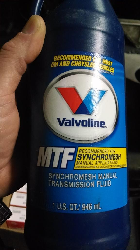
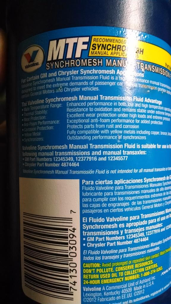
This is what I use in my AX15, works just fine. I plan on using this in my T5, too. It meets the Chrysler/Mopar 4874464 spec:

IMG_20170221_132358578_zpspfmk1irw-1.jpg


IMG_20170221_132412640_zpslwbxfwgz-1.jpg


Is this the "right stuff" for either application, who knows :crazy:

I only know that it is designed for manual transmissions, is yellow metal safe, and works great in my AX15. It is not as thick as gear oil, not as thin as ATF, maybe just right :twocents:
 
I locked up a T150 3 speed like that once, it was not pretty :crazy:

One of the gears friction welded itself on to the main shaft, blew the seals out of a press trying to disassemble it :evil:

Very similar failure on my end but it was the bearing that welded itself to the input shaft. I made it to within 2 min of JeeperDD's place when it went sure was nice to be heading somewhere that with one phone call pulled a new Transmission and had it waiting in the garage to be swapped when i Limped in.
 
Very similar failure on my end but it was the bearing that welded itself to the input shaft. I made it to within 2 min of JeeperDD's place when it went sure was nice to be heading somewhere that with one phone call pulled a new Transmission and had it waiting in the garage to be swapped when i Limped in.

I think I remember hearing about that swap :crazy: :rotfl: :cheers:


I know that I can get a T5 on the ground in under 2.5 hours by myself, way too much experience :eek::eek:


Knock on wood my AX15 holds up, I am really happy with it :fingerscrossed:


I also like the T176's, IF the shifters aren't sloppy. With the right tire size/gear combination/off road expectations, they work really well :twocents:

IF this T5 fails, it will be cheaper/easier for me to just swap in my T176, lift it 2.5", run 32" tires with its 3.31 gears, done :twocents:
 
As promised, here comes a big Dana 300 rebuild picture dump. Definitely not a step by step guide, but it might be useful.

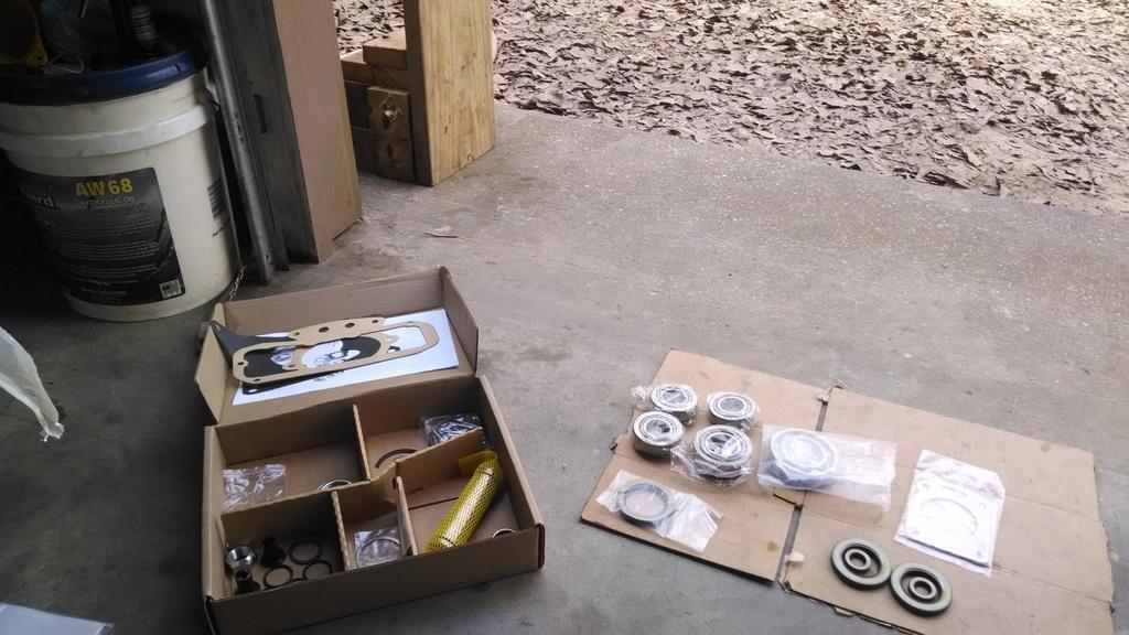
I purchased a Dana 300 rebuild kit from Novak, I like the included idler shaft, it is machined for an O-ring at each end.

IMG_20170211_150127313_zpsi09nxucb-1.jpg


New needle bearing installed in the rear output shaft. NOTE, do not drive it all the way to the bottom of the bore:

IMG_20170211_153216946_zpserc1vbcs-1.jpg


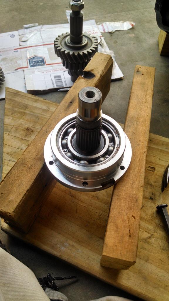
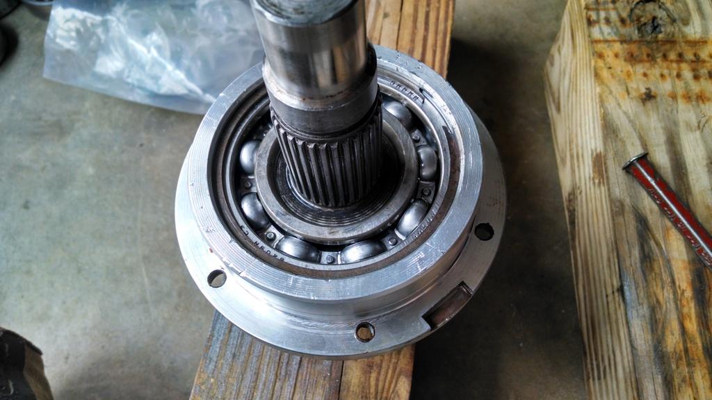
Input shaft ball bearing installed on shaft/housing, circle clip retainer installed:

IMG_20170211_155843865_HDR_zpsdglhct3d-1.jpg


Don't forget to install the new seal in the front of the input shaft housing:

IMG_20170211_155849169_zpssn0gnfu3-1.jpg


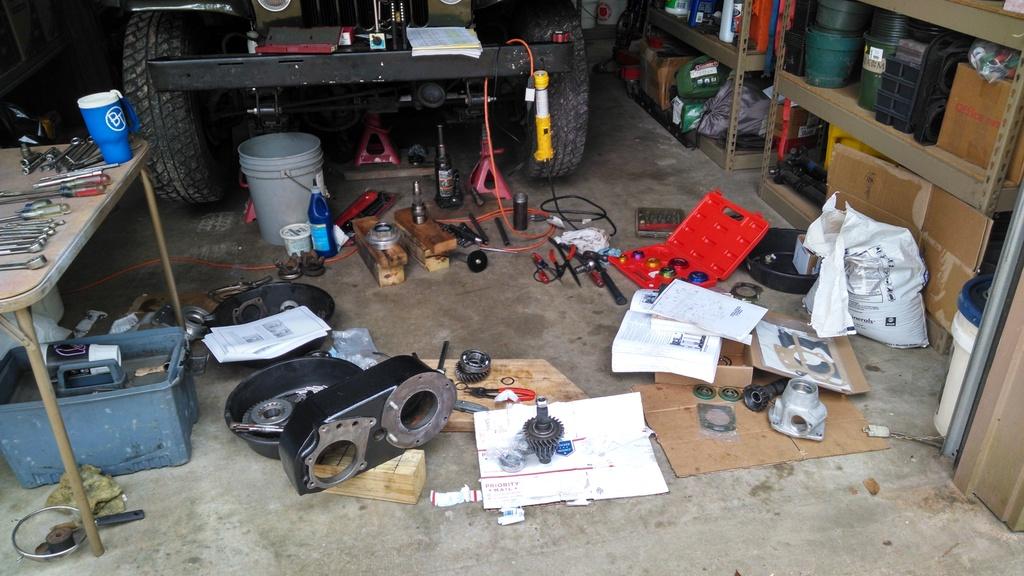
Work area is already a disaster.

IMG_20170212_095610851_HDR_zpszrmf0xon-1.jpg


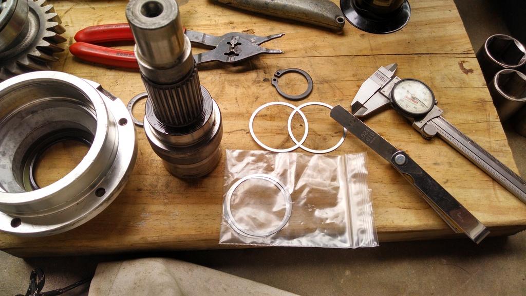
You are supposed to have 0-.005 clearance between the face of the gear that installs on the back of the input shaft and the snap ring that retains it. I have way too much clearance, .024, so I have to shim the big input shaft bearing. So, take everything back apart, install shims:

IMG_20170212_100456874_HDR_zpsodim00g3-1.jpg


Shims installed on shaft, bearing and circle retainer reinstalled:

IMG_20170212_102921499_HDR_zps1rw2rjbz-1.jpg


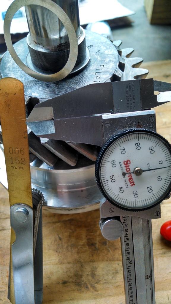
Gear installed on input shaft, clearance checked. Now, the thinnest feelar gauge I have is .006. So, I used a .004 thick shim to check the clearance. I could not get the .004 thick shim between the retaining clip and the face of the gear, so I am good to go. Clearance is somewhere between 0 and .003:

IMG_20170212_104946897_HDR_zpsreyqroui-1.jpg


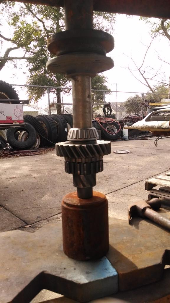
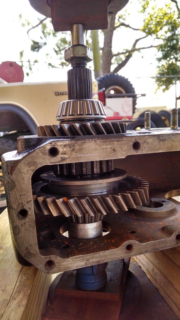
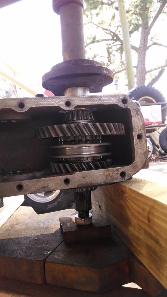
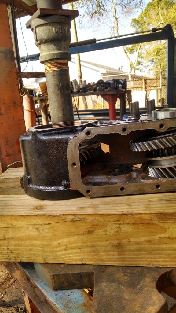
All of the input shaft assembly work was done with hand tools. The next part involves pressing bearings on to the front and rear output shafts. The shafts, gears, shift collars must be assembled inside the case, in the right orientation. I have stressed this before, but I will say it again, You must keep the case floating, with no load applied to it. You are pressing bearings on to shafts, not pressing anything into the case. Be very careful how you arrange the parts in the press, or you can end up with a cracked case. With that being said, it does not take a huge amount of pressure to press the bearings on. They should press on fairly easy. Just be careful with the case, and make sure you have the correct gears/shift collars on the shafts before pressing the bearings on.

It always takes me longer to find/make the correct pieces to use to press the bearing on. You will note in the below pictures that I will use whatever I can find that will work, i.e. press on the inner cage of the bearing and clear the shaft.

We will start with an easy one, the front output shafts front bearing. It can be pressed on before it is installed into the case. I used an old Chevrolet S10 T5 front bearing retainer, worked perfect LOL:

IMG_20170212_125332051_zpsiucu91px-1.jpg
 
I then pressed on the front output shafts rear bearing. To do this, I had to install the big gear/shift collar on the shaft, inside the case. I started pressing it this way but ran into a slight issue:

IMG_20170212_132418458_HDR_zpsqkcx1qxy-1.jpg


The jack handle got tight before the bearing was on all the way. Instead of forcing it, I took a look. The problem was that the shift collar was not lined up, so it was preventing a full press. I flipped everything over upside down, got the shift collar out of the way, problem solved. Just be careful and pay attention, do not force anything:

IMG_20170212_133505895_zpspc8144pt-1.jpg


And then the rear output shaft inner bearing:

IMG_20170212_141105311_HDR_zpszbspexrx-1.jpg


Those three bearing are the only parts that need to pressed on. Here is the partially assembled case, ready for the more time consuming steps:

IMG_20170212_151655902_HDR_zpswvwl30zv-1.jpg


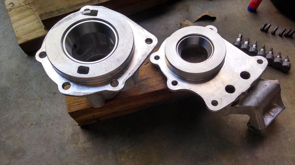
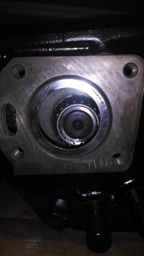
I installed the races in the aluminum housings:

IMG_20170212_155926848_HDR_zpsuz8srbwq-1.jpg


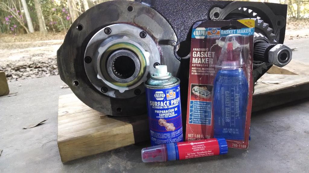
And then bolted on the input shaft housing/assembly. I always use theis anerobic sealant/primer to seal the aluminum to the cast iron case, works perfect:

IMG_20170212_163709822_zpssiqot5zg-1.jpg


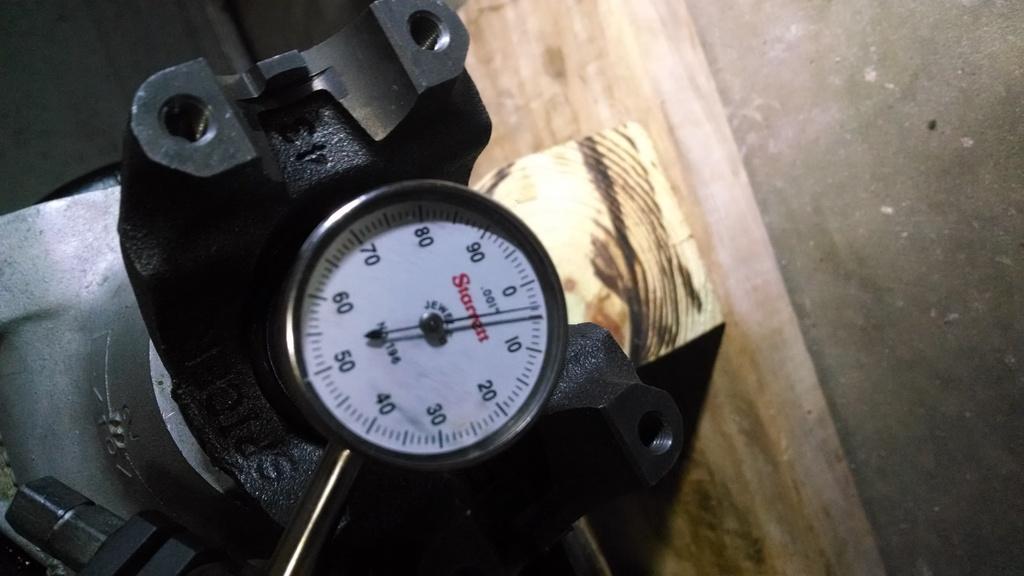
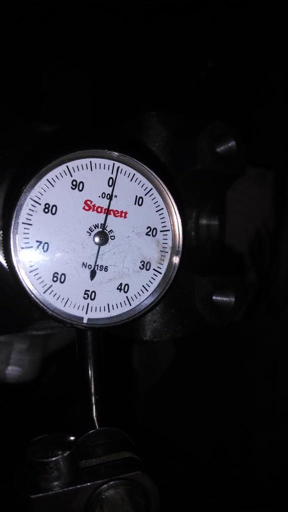
Temporarily bolted up rear output shaft housing with the original shims. It had 0 play, still turned good, but it does need a bit of end play:

IMG_20170212_172619829_HDR_zpszwkoeww0-1.jpg


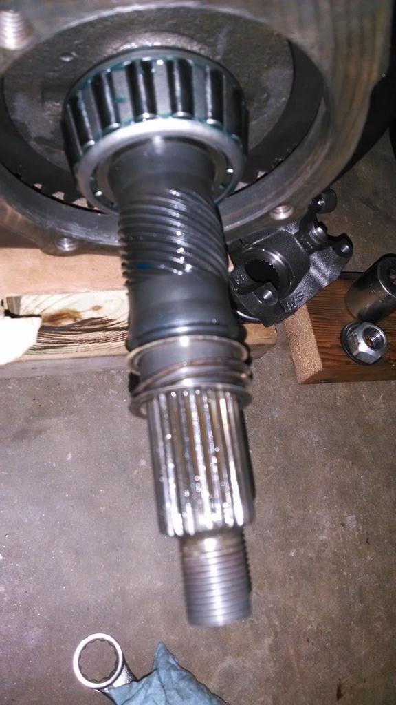
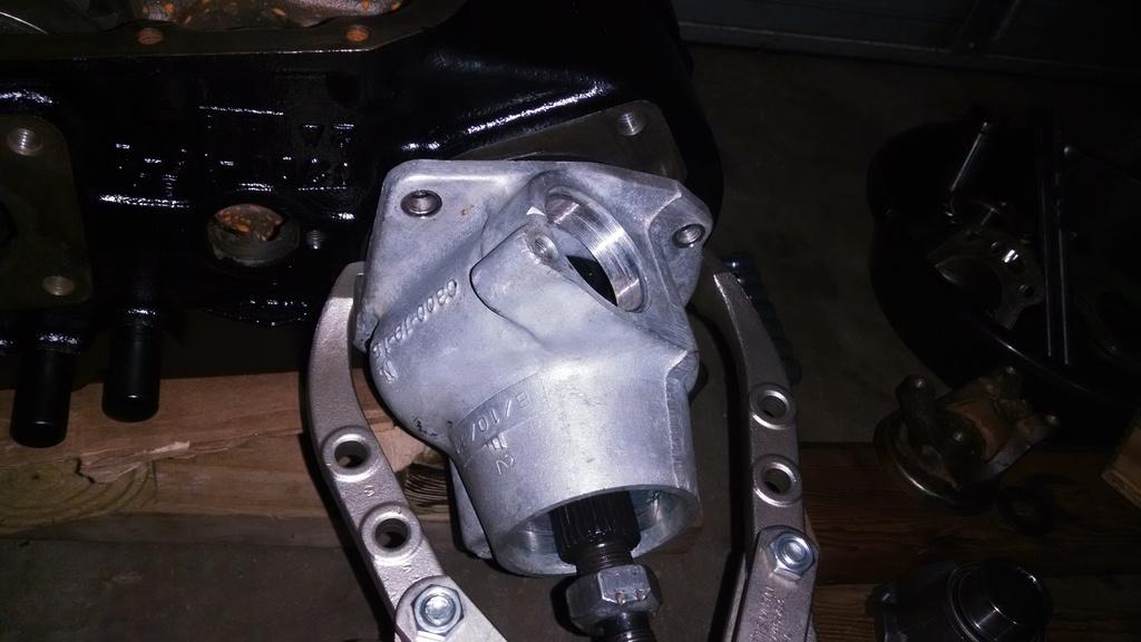
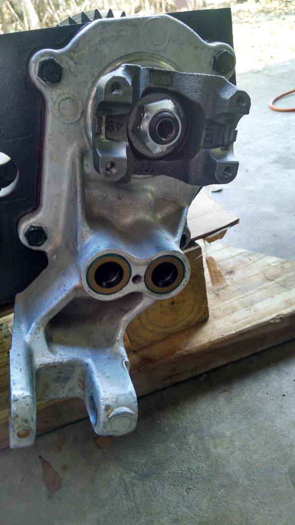
This is the most aggravating step IMO. To disassemble the output shaft assembly to re-shim, First you have to use a small gear puller to remove the yoke. Then, a larger puller to separate the bearing/shaft/housing. This is the risky part. I have cracked the rear output shaft housing before trying to get it back apart. Be careful.

Anyway, get it pulled apart, add/subtract shims as needed:

IMG_20170215_195604577_zpstqip3kwl-1.jpg


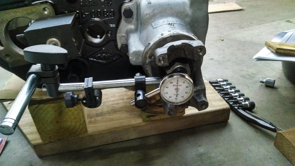
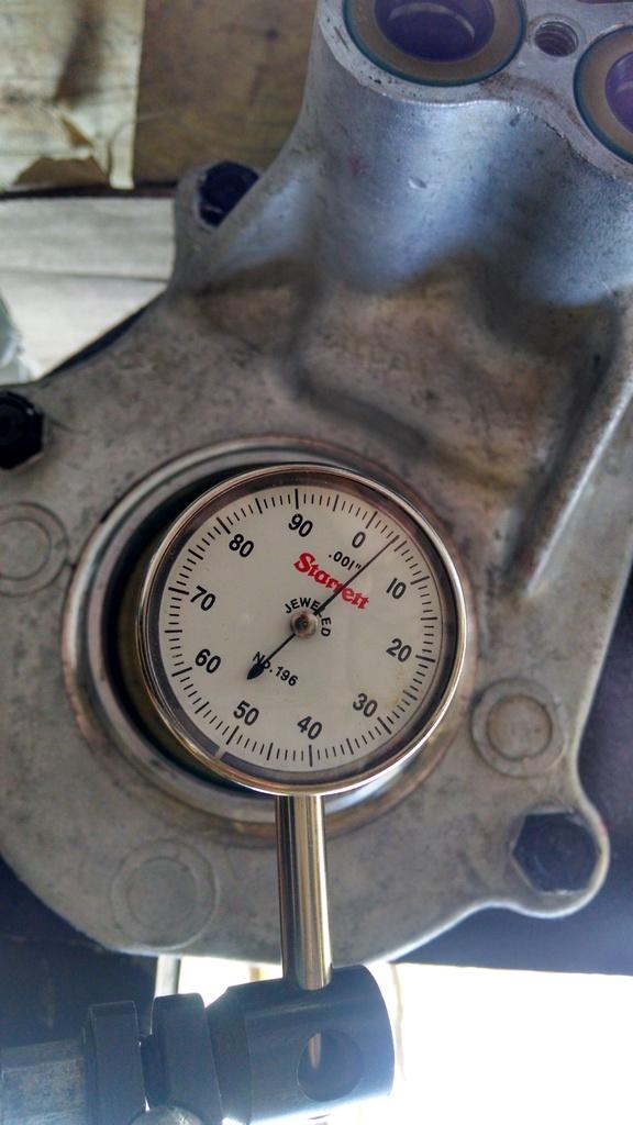
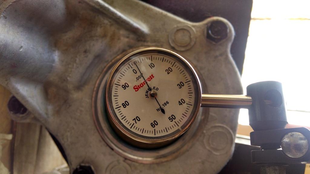
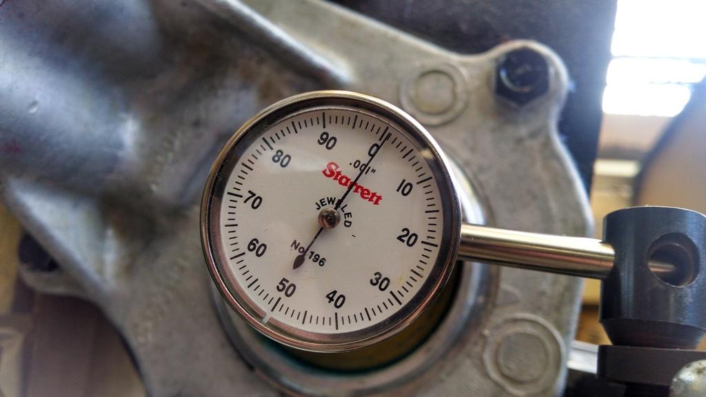
First re-shim try, OK at .004. You should have between .001-.005 endplay. This .004 is a bit too loose for me, I try for .001 with new bearings.

IMG_20170215_203930214_zpsapfvbkcn-1.jpg


Pulling it back apart. This is the "risky" step, seperating the bearing/shaft/housing with the big two jaw gear puller. Tension on the puller, soft hammer hits on the housing where the bearing is, will free it up fairly drama free:

IMG_20170215_205546297_zpsiivb2lmi-1.jpg
 
Second re-shim attempt, .001 endplay. Perfect. Everything turns free, no excessive play:

IMG_20170215_212915374_zpshqapy6ne-1.jpg


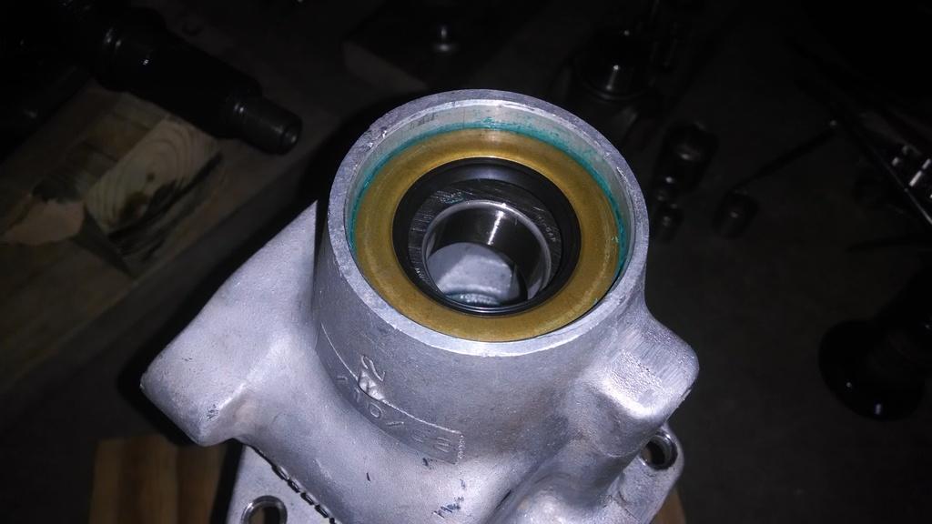
So, I now pull it back apart again, install a new seal in the output shaft housing:

IMG_20170217_172801724_zpsk76rkdlp-1.jpg


And finally, red Loctite on the new self locking nut, torqued to 120 foot pounds, one final end play check, BAM, the dishes are done:

IMG_20170217_182420099_zps5r0utrlo-1.jpg


One down, one to go.

Moving on to the front output shaft assembly, tap in the rear bearing race:

IMG_20170217_185235650_zpsrzbmpued-1.jpg


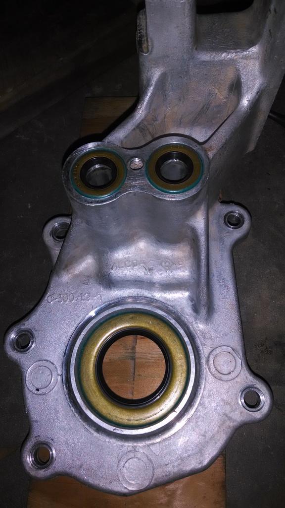
Since this output shaft end play is adjusted at the rear of the shaft, on the back side of the case, its a bit easier to set up. I installed the new front output shaft oil seal, and the two new shift rod seals:

IMG_20170217_191307011_zpsxwywljhi-1.jpg


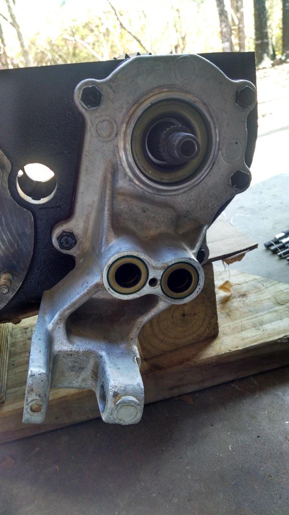
Used the anerobic sealer/primer, bolted up:

IMG_20170218_095335071_HDR_zpswv0syxzn-1.jpg


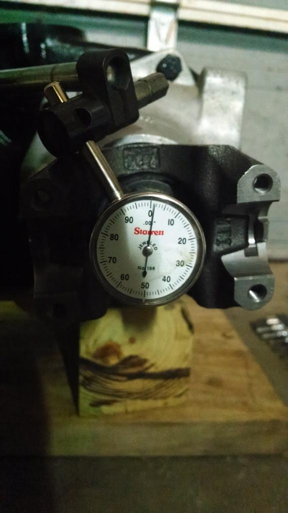
With the original shim stack, .004 end play. Within range, but too loose for me:

IMG_20170218_095716202_HDR_zpsey8qsdpr-1.jpg


Front output shaft end play adjustment, take two, better at .025:

IMG_20170218_102002520_HDR_zpsp8d1kyir-1.jpg


Third times the charm, .001 end play. Still spins free, minimal end play, good to go:

IMG_20170218_104755968_HDR_zpsohwmqq7c-1.jpg


New yoke to match the rear output, new self locking nut/red Loctite:

IMG_20170218_120716161_HDR_zpsmoarcheo-1.jpg
 
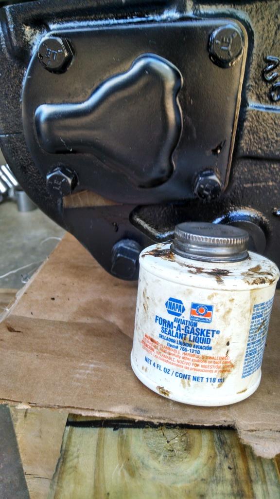
This is where the shimming takes place for the front output shaft end play, behind this steel plate. I use the sealant pictured below, on the shims and these four bolts, since they thread into the fluid filled case. Seems to work pretty good. It is thin, so it will not change the end play. Be careful if you use a thick sealant, it will increase end play:

IMG_20170218_120731847_HDR_zpsya83rk6f-1.jpg


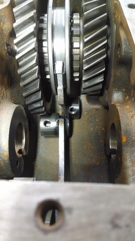
Next up, the worst part, shifter components. This part is easy, drop in the shift forks, note where/how they go:

IMG_20170218_124030836_zpssbulgwlj-1.jpg


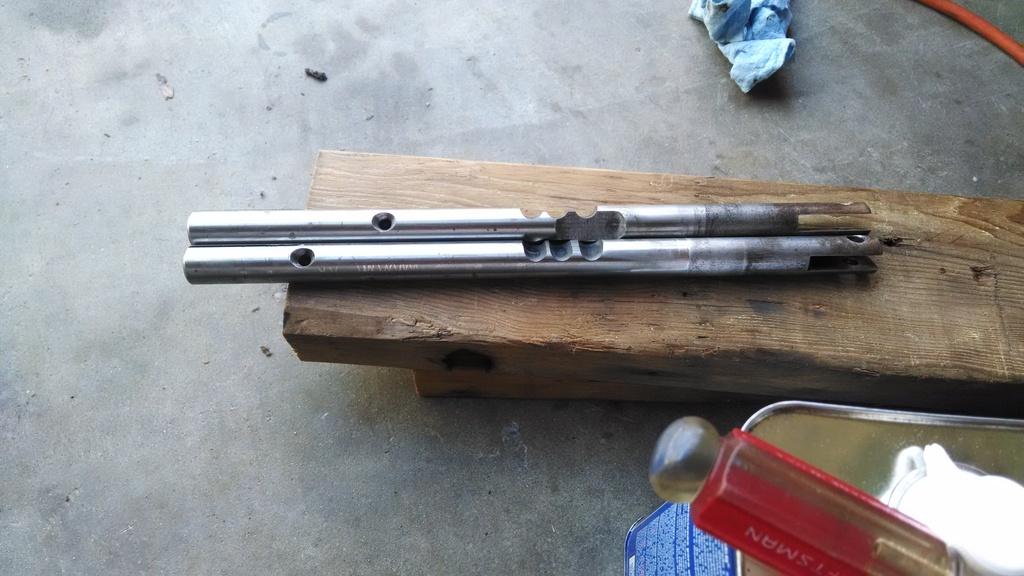
Picture of the two shift rods. They are different, so match them up with the correct shift fork. Easiest way to do this: note how each rod has an indentation where the shift forks collar set screw pins it. Note how one is closer to the rear of the case. You can also mock these up outside of the case and you can see what goes to what:

IMG_20170218_124039818_zpsbeqkqxiw-1.jpg


If you made it this far, good. This next part can be aggravating. Can be. So, drink a beer, smoke a cig, whatever. I can't tell you exactly how to do this, and I can't picture it. You start with one shift rod, slide it in, don't forget the poppet ball and spring, slide it past the ball and spring and part way into the case. Then, repeat with the second rod. The trick is, you will have to rotate the case around/flip it up on end to make the little slide pins, that are between the two shift rods, get out of the way. You also have to twist the rods 90 degrees. Like I said, I can't give you a step by step. You just have to do it. Whatever you do, don't smack the shift rods with a hammer!!!!!!!!!!

Once you get them in, it will be a "Eureka!!!!" moment. Cherish it.

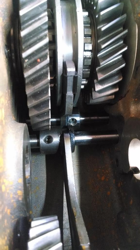
The money shot, both rods installed, lined up with the shift collars, before set screws are red loctited into place:

IMG_20170218_143640044_zpsgtwnfbok-1.jpg


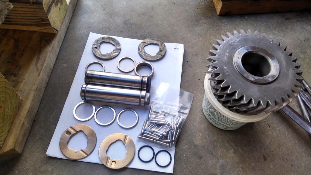
Last major piece of the puzzle, and the easiest IMO, the idler gear assembly. New parts on the bottom, old on top. Note the double o-ring set up on the Novak replacement shaft, pretty slick IMO:

IMG_20170218_150316338_HDR_zpseqd4ioic-1.jpg


Use some grease, install the two rows of needle bearings and the three spacer rings:

IMG_20170218_151624059_HDR_zpssbdfyswk-1.jpg


The FSM/other sources say to make a "dummy shaft" to hold the two thrust washer in place. I never had to do that. I hold the rear washer in place with the idler gear shaft, I hold the front one in place with a big socket:

IMG_20170218_151632533_HDR_zpsgaalvoqr-1.jpg


And the idler gear installed. It is a tight fit. The shaft will tap through pretty easy, as long as none of the needle bearings falls out, and the thrust washers stay in place. You shouldn't have to beat the crap out of it.

IMG_20170218_152341619_HDR_zpsqkzabru0-1.jpg


Install the square steel thing into the notch of the idler shaft at the rear, don't forget the ID tags:

IMG_20170218_154054268_HDR_zpsdqri5qd8-1.jpg


Bolt on the shift rod guide on the front end:

IMG_20170218_154114094_HDR_zpsuuqu4ikw-1.jpg
 
Last edited:
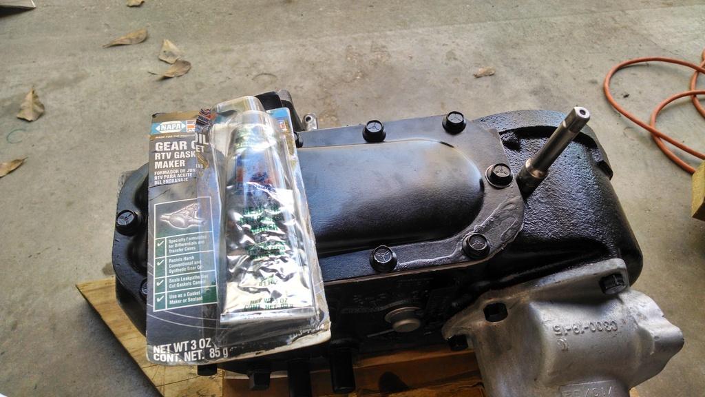
I used a thin coat of this RTV on both sides of the new pan gasket:

IMG_20170218_160420162_HDR_zps6jpgacng-1.jpg


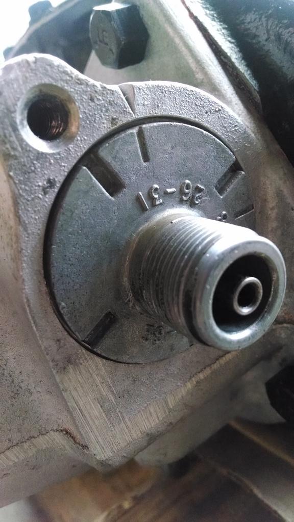
Speedometer gear thing installed. Mine has a 30 tooth gear, seems to work fine with the 30" tires/3.31 gears. Note the slot lines up with the notch on the housing:

IMG_20170218_163113299_zpstswatqhg-1.jpg


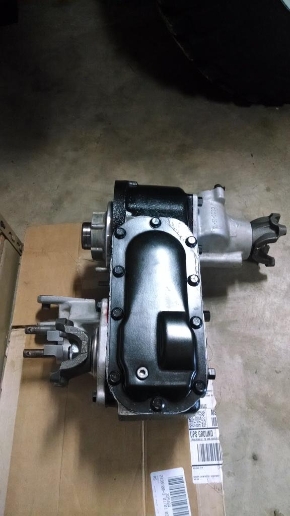
Ta-Da, FIN:

IMG_20170219_111005272_zpsoewg7aav-1.jpg


With its brother from another mother T5:

IMG_20170219_111014937_zpspz8vnzeu-1.jpg


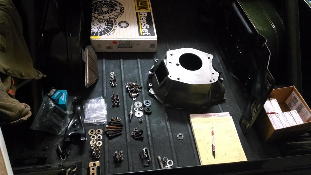
Most of the other parts/pieces needed:

IMG_20170219_111039371_zpsnvq4czvc-1.jpg


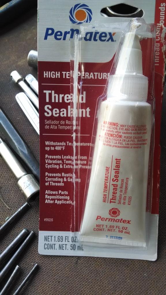
Quick Note - I tried out this sealant on this T5/Dana 300 rebuild:

IMG_20170219_111100226_zps1hutslfq-1.jpg


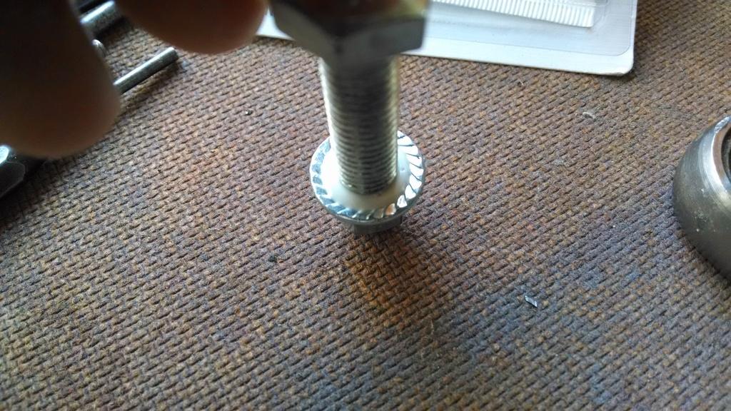
There are quite a few bolt that thread into the fluid filled boxes. If you don't seal the threads, they will leak. Anyway, I did a test. Applied some to a bolt, threaded on a nut, let it cure for four hours:

IMG_20170219_111109999_zpsqj3qtwft-1.jpg


It sealed up tight, and has locked the nut in place. I hope it works in the real world :fingerscrossed:


Next task, pull the old engine/emissions/stock carb stuff.

That't it for now :wave:
 
Very similar failure on my end but it was the bearing that welded itself to the input shaft. I made it to within 2 min of JeeperDD's place when it went sure was nice to be heading somewhere that with one phone call pulled a new Transmission and had it waiting in the garage to be swapped when i Limped in.

One stop shopping! When building Treblehooks black laredo he always got excited when we went "shopping", as he called it in my basement.
 
I'd like to add some information about needle bearings here (I hope it's not too late):

needle1 - 1.jpg

This is called a drawn-cup needle bearing. It starts out as a drawn cylindrical sleeve (like DOM tubing), then one end is curled under to support the rolling elements (needles). At that point, the curled end is usually stamped with a part number, then flame hardened (you can usually see the hardening line about 1/8" high around the base).

Once this "cup" is formed, the rolling elements are placed in, and the un-hardened edge is curled over to keep it all together. This edge is not hardened, because the heat could affect the integrity of the rolling elements and the retainer.

So, when installing a drawn-cup needle bearing, you always want to press on the end with the part number, because it is hard. If you press on the other end, it could crush down against the needles, and prevent the bearing from rolling.

Unfortunately, I don't see any part numbers in this photo, and the end of the bearing which I'd expect to be somewhat round, has been pressed flat.

This doesn't mean the bearing is ruined... but if possible, you should stick your pinky in there and make sure the needles are free to move.

I hope I'm wrong! :wave:
 
So, when installing a drawn-cup needle bearing, you always want to press on the end with the part number, because it is hard. If you press on the other end, it could crush down against the needles, and prevent the bearing from rolling.


That's a good well unknown by many piece of info right there-
 
I'd like to add some information about needle bearings here (I hope it's not too late):

View attachment 58043

This is called a drawn-cup needle bearing. It starts out as a drawn cylindrical sleeve (like DOM tubing), then one end is curled under to support the rolling elements (needles). At that point, the curled end is usually stamped with a part number, then flame hardened (you can usually see the hardening line about 1/8" high around the base).

Once this "cup" is formed, the rolling elements are placed in, and the un-hardened edge is curled over to keep it all together. This edge is not hardened, because the heat could affect the integrity of the rolling elements and the retainer.

So, when installing a drawn-cup needle bearing, you always want to press on the end with the part number, because it is hard. If you press on the other end, it could crush down against the needles, and prevent the bearing from rolling.

Unfortunately, I don't see any part numbers in this photo, and the end of the bearing which I'd expect to be somewhat round, has been pressed flat.

This doesn't mean the bearing is ruined... but if possible, you should stick your pinky in there and make sure the needles are free to move.

I hope I'm wrong! :wave:

That is some really good information.:thumbsup:

Hope it's okay.:fingerscrossed:

That's a good well unknown by many piece of info right there-


Yes, you are correct, I technically installed this bearing upside down. I think I have installed all of them upside down, Dana 300's and Dana 30 spindle bearings. But, with no problems. The needles still move fine, the metal is not crushed.
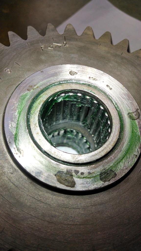
The stamped end is generally/supposed to be thicker/hardened, so that end should face up. I have successfully installed them upside down numerous times, not that it is the "correct" way to do it, but it can be done. These bearing in this application are not a super tight press fit. So, they lightly tap in place. Using a socket, which is not flat, they have a "bevel" face, you are putting most of the force on to the outer portion of the steel cage, not the flat lip. So, they tap in fine.

The reason why I install them upside down, which is not the correct way to do it, is because of how they are made. The stamped end usually has like a 15 degree bevel to it, around the edge. The non stamped edge has no bevel. It is easier to start the bearing with this beveled end down, it centers it up in the bore easier. This is not the correct way, but it will work, as long as you press the bearing just along the outer shell edge, NOT the flat face.

But yes, you are 100% correct, I have installed this bearing, technically, upside down. :thumbsup:

But, the bearing is fine, the rollers still spin/move perfectly. In the future, I should install them the correct way, to lessen the chance of damage during installation :cheers: :thumbsup: :wave:

Thank you for pointing this information out, it is very helpful :thumbsup::cheers::wave:
 
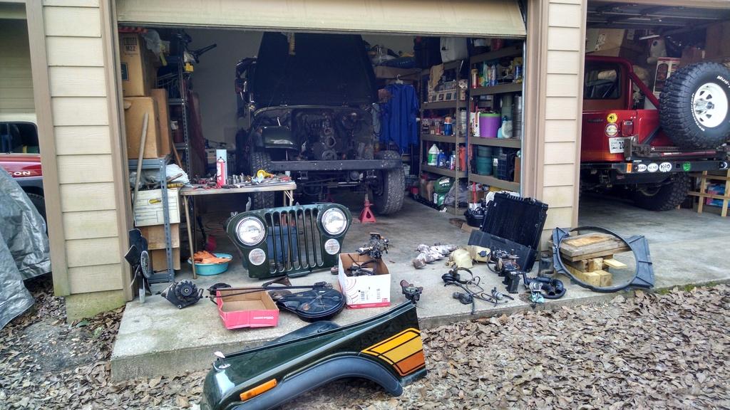
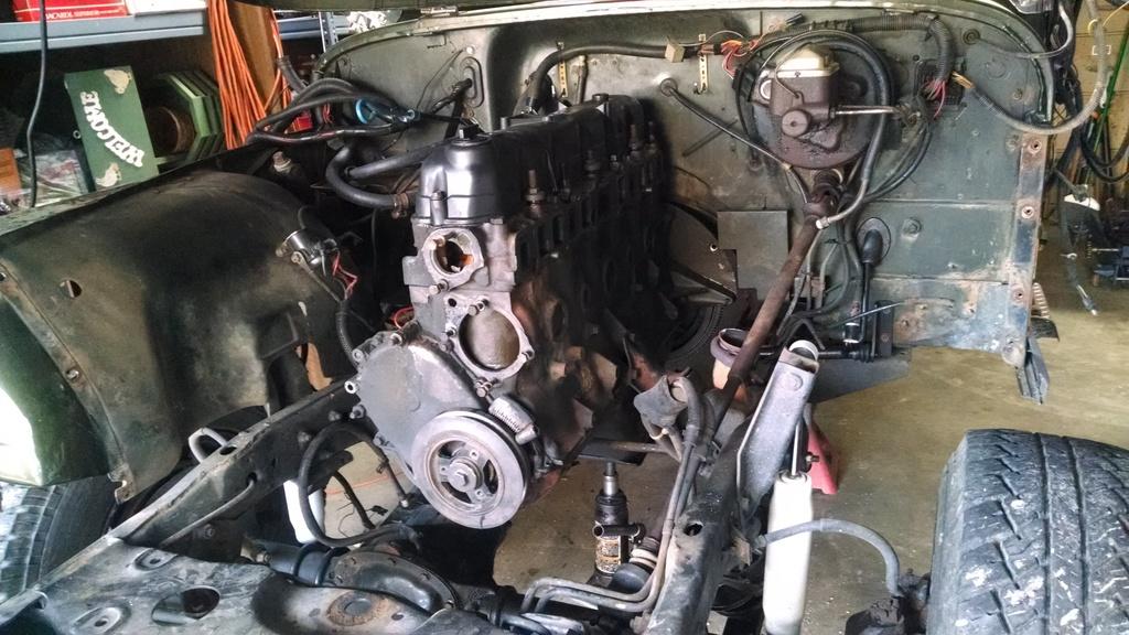
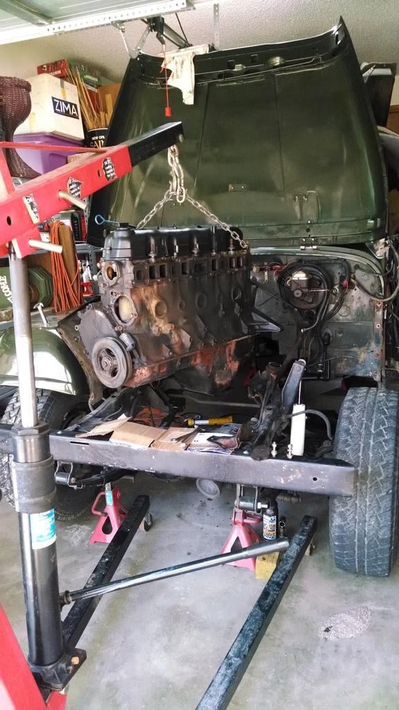
I was able to get the engine pulled out this weekend.

A bunch of stuff to remove, before the actual engine :eek:

IMG_20170225_162023977_HDR_zpshwzmyabs-1.jpg


I carefully removed all of the underhood emissions/Carter BBD feedback system parts. I still need to pull the computer/wire harness. I plan on keeping all of this stuff, definitely hope I don't have to reinstall it on one of my Mopar MPI injected engines.


Ready to go:

IMG_20170225_162039993_zpsxj2dlsz3-1.jpg


A bunch of work to get to this point:

IMG_20170226_115057025_zpscpd2qqfq-1.jpg


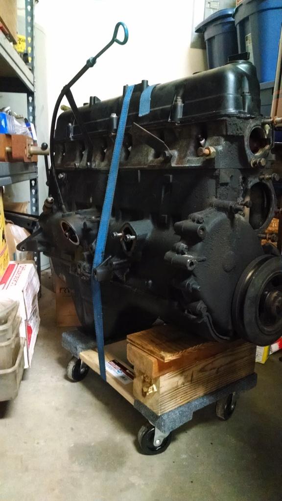
The $10 Harbor Freight 1,000 pound capacity furniture dollys make great rolling engine platforms when you add a ratchet strap :twocents:

IMG_20170226_133617708_zpsjocead92-1.jpg


I plan on keeping this engine in a corner of the garage, as a rebuildable core, never know when you might need an engine. This one still runs good, but has low oil pressure at idle, makes a strange noise sometimes when it was shut off.


I plan on cleaning up the firewall/inner fenders/frame rails while everything is out, plus I need to paint a few misc parts. So, still some work to do before I can start reassembly. That, and I still need to go get my motor :rolleyes:

That's it for now :wave:
 
The 258 I rebuilt for my blue jeep ran pretty good before I dug into it also. It just had low oil pressure, no knocking or anything wierd. Upon disassembly I found 2 broken piston rings, a cracked piston and a burnt valve. Not to mention a ridiculous amount of wear on everything. My friend was with me the last time it drove and didn't believe me at first that it was the same engine because of how bad it looked internally. When I first got the jeep it did run and drive, but was very rough. I did drive it home and found that the plug wires were in the right order on the cap, just going counter clockwise instead! I don't think more than 2 cylinders actually fired at the right time. But it did run. Once I switched them around it ran great. I really didn't expect it to be that bad when I pulled it apart. Sorry for the rambling, I am just amazed at what these engines can go through and still run.
 
The 258 I rebuilt for my blue jeep ran pretty good before I dug into it also. It just had low oil pressure, no knocking or anything wierd. Upon disassembly I found 2 broken piston rings, a cracked piston and a burnt valve. Not to mention a ridiculous amount of wear on everything. My friend was with me the last time it drove and didn't believe me at first that it was the same engine because of how bad it looked internally. When I first got the jeep it did run and drive, but was very rough. I did drive it home and found that the plug wires were in the right order on the cap, just going counter clockwise instead! I don't think more than 2 cylinders actually fired at the right time. But it did run. Once I switched them around it ran great. I really didn't expect it to be that bad when I pulled it apart. Sorry for the rambling, I am just amazed at what these engines can go through and still run.

Yep, my red Scrambler's 258 ran great with a cracked piston skirt, just made a ticking sound :rotfl: Not sure about this engine's internals, it is still assembled sitting in the corner. I am going to hang on to it as a spare, hopefully re-buildable core. It still ran fine when pulled, just low oil pressure at idle, wierd sound every once in awhile. I never even checked the compression :shrug:

No problem with the rambling, glad someone is reading this stuff :cheers: :wave:


Love that green:smokin:

Wait till you see the next post, I performed some "magic" to the original fire wall paint :drool:
 
Back
Top