• Notice for iPhone users: DO NOT use the image size reduction option when uploading photos to the forum. This causes portrait images to post as landscape. We have added a warning to the image insert pop-up as well.

Torqueflite 999 rebuild

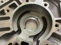
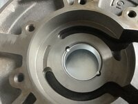
Pressing in a new bushing in the pump again. This time I used a race driver with the hydraulic press. I went really slow, I mean really. I pumped the jack without a handle, just the short no leverage part the handle slides into. This gave me more feel for the pressure. If the bearing started going crooked, immediately stop and readjust. Little by little press it in.

DC1AA3B9-AC9D-43CD-A9EE-1A8F8E397F9D.jpeg 976008F2-BE28-4EFD-B75B-4A060297A244.jpeg

After pressing in the bushing, stake the two sides with a blunt instrument, I used a HUGE screwdriver. Once it is staked, take a fine file and deburr the stake to ensure the bore is round.

F62488BA-38FA-4716-8E75-50685A80B42F.jpeg

I used a Babbit bearing because it is softer, some TC brands require Babbit as the hub is not hardened. I would rather the bushing take the punishment, not the TC hub. Just my opinion. Next up is the TC hub seal.

TTFN
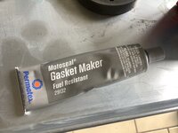
 
Next up, press in the TC hub seal. Spread a THIN layer of RTV sealant around the seal. Press it in. I used the “mid grade” grey RTV.

3CF00868-5F3B-41A6-B86E-F6E36F689DD5.jpeg 237BB91C-9249-4B98-8A55-FDED0F3F76BC.jpeg

Time to lightly grease the pump cavity and pump. The goal here is to prevent metal on metal contact while sealing the “gaps” to allow it to pump immediately. Not to fill it completely with grease.

AA7E7F70-3607-4E6E-AF42-A88008F5FFD4.jpeg 9CCA78B4-6275-4F23-A740-65413AFBAE8B.jpeg B9753227-C2FF-4FFE-9CCC-B9E6F4B57854.jpeg B0389344-2E85-4918-9522-923B2805B214.jpeg
 
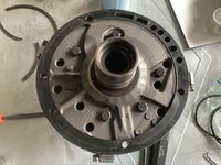
Bolt the two pump halves together. Just lightly finger tighten the bolt, you want the two halves to slide around a little, but not to have space between them.

7DA2B3E2-1A48-4108-AD17-6FA3203F3315.jpeg DFFACE56-8A87-4EB9-B048-65AA24403B11.jpeg

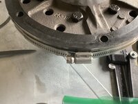
After the bolts are lightly installed, use hose clamps around the perimeter to align the two pump halves.

745EE995-C7B4-4C0F-8F41-0E31ED672FB8.jpeg 81C4BC91-2B0E-42AB-9642-0AEB648BE05F.jpeg

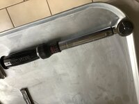
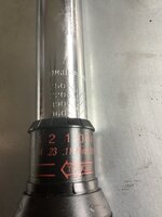
Once aligned, tighten the bolts to 160 INCH-Pounds. (Not FT-LBS) Tighten in a star pattern.

CB31C99A-B9C0-44B3-B866-C78BD6C084BD.jpeg 0F218F93-D136-454F-9675-ABFB6ADA0FC4.jpeg 0F5A84B4-DBB4-43F3-8ABE-215058480B94.jpeg
 
Remove the hose claps, and grease all bushings, seals, hubs, perimeter.

38811EB6-BCB7-4E2C-95D7-F2AE0555AA9A.jpeg 47C0FD6E-F41B-43FB-9305-4F7C45D29E5D.jpeg

Install the perimeter seal. Install the two hub seals, ensure the ends interlock and that they are 180 degrees from each other.

9F133818-AFD1-4D4D-A9F1-1E89502474FB.jpeg

DDN’T do like I did, fail to remove the pump to case seal and need to remove it after everything is assembled and greased up.

84AAA1F1-5998-47FD-8F1E-B89470C8FE40.jpeg

Once it is clean with fresh grease and seals installed and the seals greased, place it in a clean location for installation later.

C6A0D893-ABD6-467A-99E1-B66134BE6ADB.jpeg

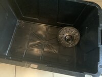
I am using a storage tote that has been cleaned.

TTFN
 
Had a blast watching people burn through ammo like it was water. The grins on the faces was great. We estimate around 3,000 rounds were shot most over a 2 hour period. Went through almost 2 cases of 5.45x39 alone, but that is to be expected at an event centered around the guns designed by Mikhail Kalashnikov - Kalash Bash. (I might even have been responsible for a few of those rounds going down range. :D:usflag::D) They are back at it again today, they hope to shoot another 3,000 rounds today. One day was enough for me though, I am beat.

On to the front clutch and rear clutch. Remove the snap ring with a pick or small screw driver.

E301B2FF-2F43-4C33-B4D3-929282CC58AB.jpeg

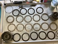
The rings, plates, and frictions are laid out in order of assembly. (Up down up down, two rows for space sake.)

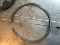
The broken ring measures 0.050”

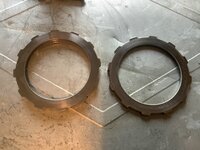
The steels all measured between 0.065” and 0.068”

The rear clutch ring measures 0.075”

Forward snap part numbers:

0.061” - 4130761 (WIT #12878)
Wavy (0.0xx” ?) - 3410571 (WIT #12878A)
0.076” - ? (WIT #12878AA)
0.098” - ? (WIT #12878AB)
0.085” - ? (WIT #12878AC)

Steels part numbers:

0.068“ - 1942403 (WIT #12126)
0.068” Kolene - ? (WIT #12126A)
0.088” - ? (WIT #12126X)

There are so many options for frictions, I can’t list all variations and part numbers. There are tan material, red material, kevlar lined, race, grooved, waffle, etc… then there are thin, thick, stock. And many variations of friction type and thickness. This is where transmission builders do their artwork to make custom build (as well as other places).
 
Gotta shift gears (ha ha, you are so funny) since I am waiting for parts. Assemble the tail housing adapter.

Press in a new output shaft seal. Use a light coat of RTV around the perimeter.

C3432A42-66F7-4C03-A7F2-04B83A995B82.jpeg

After cleaning the parking pawl parts in Evapo-Rust in the ultrasonic cleaner, reassemble in the housing. Fairly straight forward.

FAE29C65-4C82-4580-93C6-5A131B7A7A98.jpeg F55EFC70-AAB2-44FA-9B11-058825ED0434.jpeg

D0F6BF0A-B6B7-4C7B-B75B-BF0D123D6F3B.jpeg 8456DF8D-E61F-4B40-8400-32D84180104E.jpeg

Use a couple wraps of Teflon tape to seal the port plug, not sure if this is a hydraulic test port or a drain. Torque it to “snug enough”.

8BADF0A0-FADA-4B21-8D36-603532D11144.jpeg

Place it in the clean room, I threw a couple silica desiccant packs in there to keep it all dry. (Houston 125% humidity and all.)

CAC758C1-CAD7-4377-9178-77A6C4B4CA26.jpeg

TTFN
 
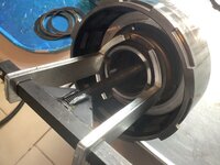
Got some parts in today, but more importantly I got a new tool. I highly suggest the clutch spring compressor tool, it only does one thing, but does it so well. Much safer than c-clamps that would most likely slip and allow parts to fly around. This is a VERY strong spring.


I used the tool to compress the spring in the front clutch to remove the piston. It is kinda fiddly to get the fingers just right where it grabs the retainer, but still allows room to remove the snap ring.

5E19EBB0-0A2B-48EB-ABC2-441BF8444183.jpeg FF01518E-F669-4C4E-A791-21B21A77A691.jpeg A4A35546-D284-4786-BA72-46B15F2158A1.jpeg

Once the spring is compressed, remove the external snap ring, I used a pair of Wilde G705 Lock Ring pliers.

Parts disassembled.

5257081D-BF6E-4EC8-A055-EB24BC8A62B0.jpeg

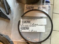
Recieved the replacement snap ring for the clutch pack, but this is 0.085” the previous one that is broken was 0.050”. Hope I can rebuild with th proper clearances, otherwise I might need thinner steels to compensate. I do have a NOS original on the way, maybe it will be thinner, but I doubt it will be 0.050l.

DFDF138E-689F-4A2F-B6B7-446BBF46B045.jpeg

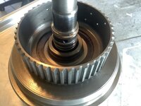
Here is the location of the sealing ring on the front drum.

741D7C10-3E49-46D9-934D-F6FE659F9231.jpeg

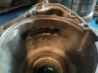
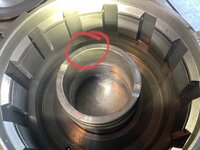
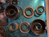
Front drum bushing condition and location / depth. I don’t have one of these bushings, back to p house to get one, hopefully tomorrow if time allows. This bushing is showing significant signs of wear.

037EB6E7-6554-467C-BC74-CA8522698535.jpeg 4EBEDE09-C656-4BD6-A054-45C87FA5EEB8.jpeg

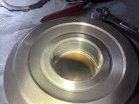
Reverse side of the drum / bushing. This area seals to the pump rings previously installed. The bushing rides on the pump.

0D81A604-F5D2-4F39-A11B-21903AF260F4.jpeg

Next update after more parts purchases. TTFN
 
Got some more parts in today. Some local, some mail order.

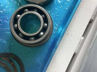
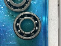
First, the bearing from A&A, nogo. Outside is a different diameter and inside does not slip over the output shaft. Slides over splines, but won’t go over the bearing surface. Here is an original bearing with the new one on top.

18D6816A-93E7-4B18-9905-8B1306182763.jpeg 7461F579-6C15-44FA-B653-4B94C2992080.jpeg

I’m calling the original bearing unobtainium now. Only solution if the original bearing is bad, get a good used one from a salvage yard or use a larger inner diameter bearing and machine a shim.

I also got my selective snap ring set from A&A, hopefully I can get the proper clearances with one of these.

B77F81D7-3DEC-4784-920D-B6FDEF6F6DAD.jpeg

I also got new bushings for the various drums and gears. FYI, WIT is less than 1/2 the cost of Transtar. I highly suggest getting as much from WIT as you can. Prices are just that much better, but Transtar has more selection. While I was at WIT today, I saw an interesting letter dated October 2019. It was from BorgWarner regarding bands. The demand for bands is at 3% of the peak demand (as of 2019). Apparently none of the newer transmission designs use bands, they all rely on clutch packs. At first I thought I read it wrong, but it did say 3% of peak demand. That is some major decline in demand!
 
Don’t do what I just did! Pressed out the bushing and cracked the clutch retainer. Grrrrrrrr

C91111E0-2686-4265-A30F-15D5B9CF2118.jpeg 2A9AB761-75B4-4633-94BD-C966C9E026CC.jpeg

Got a replacement ordered, friggin $75 mistake. Dumb one at that. Lesson learned, don’t rush a process.
 
Last edited:
Sounds like you have a parts transmission now. Spares. Is it aluminum ?
 
Last edited:
Sounds like you have a parts transmission now. Spares. Is it aluminum ?
Not yet, at least I hope. I ordered a used part, should be here this weekend or early next week. A&A makes “race“ retainers out of aluminum, but the stock one is steel. It was an aluminum bushing driver that wedged in the bore and cracked the retainer.

Hopefully the replacement is the right part. :fingerscrossed:
 
After getting done licking my wounds and once I finished sulking over a stupid mistake, I decided to press on. To the rear clutch…

Remove the thrust washer and verify the thickness. This one is at the maximum thickness, that is great, plenty of wear left.

E7E90FE4-3349-49D8-8FE5-A1E5D0C7EB15.jpeg 8603688A-8160-459A-8802-C294A49D14C2.jpeg 5C9D0E2A-CACE-44FA-904F-C923B4AB80C8.jpeg

Now, remove the sealing rings on the input shaft. The current rings were Teflon top and iron interlocking bottom. My rebuild kit only included Teflon top and bottom. Don’t forget the larger one between the bottom ring and the thrust washer, on the step in the shaft. See below for the replacement of this sealing ring.

23D52C7E-6663-4B79-9319-77A4100CDBAE.jpeg 93396196-DF13-4E7C-A6B7-85721629AE8F.jpeg

I had previously removed the snap ring and the steels / frictions to count them. They are assembled in this order: Snap ring, flat pressure plate, friction 1, steel 1, friction 2, steel 2, friction 3, steel 3, friction 4, beveled pressure plate. See top 2 rows.

409CB68C-A394-4FB5-9F91-35C6EF99BC77.jpeg
 
Last edited:
Remove the wavy snap ring, and Belleville spring, then remove the piston. My wavy ring had some crud built up on it, so I ran it through the ultrasonic in evapo-rust. I also ran the two pressure plates through as well to ensure any rust was neutralized. After the evapo-rust they were washed off in the mineral spirits. All hard parts had a final clean in the mineral spirits. Both to clean them and give them an oil coating to protect against humidity. I pulled the snap ring on the end of the input shaft, but the clutch retainer is pressed on the shaft and must be pressed out, mine looked good so I left it alone (learned my lesson).

C3F2E009-4AA2-463C-993A-A90DF965439B.jpeg BF57EABE-2724-47C7-90C8-199E586D7A26.jpeg AE2A1403-09F9-4854-8154-786DD3CBC91A.jpeg A73D37F9-EABF-483F-AF41-B752BFF3F06F.jpeg

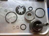
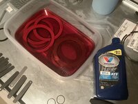
After everything was clean, I replaced the seals in the piston, lubed it all up with the asemblee goo. I tried using a piano wire tool on the perimeter seal, but it got stuck and did not work great. I had better luck dropping the piston in and gently pressing down while rotating. After a little work, it popped right in. Next, insert the Belleville spring, cone down towards the piston, then reinstall the wavy snap ring. There is a third sealing ring on the larger diameter portion of the shaft, replace this iron ring with a new iron ring. These have interlocking ends. Old on left, new on the right. The finished product looks messy, but it is all grease that will dissolve once the transmission starts pumping fluid.

E7BF74D1-76CD-497D-A00E-102F353520A6.jpeg 311F1F86-FC91-43DE-A789-31EC6842BEA0.jpeg

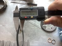
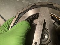
Next up is the clutch pack. One of the reference books instructs to check the clearance dry, the other book instructs to check it wet. I tried both ways. First photo is clearance dry, second is wet. I hade 0.045” both ways. I am almost in the middle of the acceptable range. (0.032” - 0.055”) I might use a thicker snap ring to tighten up the clearance, but this is well within acceptable limits so I might just leave it. Tighter tolerances will provide quicker shifts, too tight will result in dragging clutches when not engaged and possible overlap between clutches engaging and disengaging. The current snap ring is 0.075”, I have one that measures 0.084”, so I could remove 0.009” resulting in 0.036” clearance. (This would be 0.004” over the minimum specification, I am currently 0.013” over minimum and 0.010” under maximum.)

49B26DB2-4E1F-4228-BC9C-B2B66CD9B791.jpeg 634A439A-09F5-4AD4-933D-5A9CD8D550BE.jpeg 120751CC-A908-49FB-A066-E6860974CD1B.jpeg 0390E152-58AF-4881-A70B-4E32D0ABD1A1.jpeg

Next, I used the slippery stick to goop up the seal grooves on the input shaft. I used more on the seals. Installed both seals being careful the scarf joint was properly aligned and the the joints form each seal were 180 degrees from each other. Them I placed the assembly in a zip lock to contain ATF drips and set it in the clean box for later use.

TTFN
 
Last edited:
Next step is mostly cleaning and inspecting. Parts are in order of assembly.

3F0BC3AB-583D-403C-A7AF-DCC71CBB80C5.jpeg

FD92EE0A-2624-4F15-B2DC-C6EA631EE3EA.jpeg 6A50738B-A7CD-4F1F-84E3-746B928C6E82.jpeg 3899919A-C57A-46B5-85B1-427C1B6DF104.jpeg 2F59C8E7-44B2-4CB8-AB21-C981EB3904F7.jpeg

64359341-5002-4510-BAA4-FE6566399BEB.jpeg 912608F3-E843-4AC5-9E5C-A48C4BD9616B.jpeg

In the top closeup photo on the left, the front ring gear comes apart by removing the snap ring.

AE9B5BA1-896C-4310-B570-509BD4E69B04.jpeg

On the bottom right closeup photo, the rear ring gear also disassembles by removing a snap ring.

B7CD4A1A-A2E3-4737-A63A-D0FD08CC5CC5.jpeg
 
Last edited:
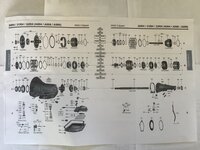
WIT has a good diagram of the transmission parts exploded, to get a part number add “12” to the number in the diagram.

00962C6A-01F9-457D-9D99-1895423900E5.jpeg

A9CE0516-7D19-46A1-9001-A8095D152BA4.jpeg 5F631756-95A1-4FF6-9BDC-F712104DE6FB.jpeg
 
Got my replacement front clutch retainer. It was scheduled for delivery, but somehow USPS got it here today. Shocked! :oops:

It came complete, retainer, snap rings, spring, steels, frictions, pressure plate, piston, bushing. Now I have several spare parts.

I will work on it tomorrow.

2BEAE956-BE42-48A8-A962-C758A8B80674.jpeg

Bottom is “new” top is the old broken one.

TTFN
 
Started reassembling the gear train. First the front annulus gear. Called the forward ring gear in some catalogs.

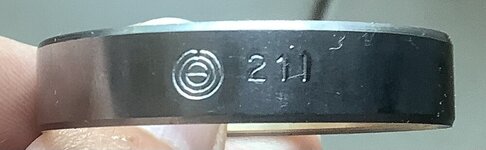
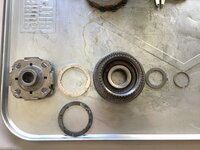
The ”inside tab” thrust washer (12238C) stacks on the planetary, then it sits in the ring (12592), the gear support (12602), slides into the splines of the ring and is secured with a snap ring (12882). The snout of the planetary has a thrust washer (12234) and is secured with a snap ring. The front annulus gear has a bushing (12050), mines was in good shape, so I left it alone. Tom Hand indicates the TorqueFlite transmissions are easy on the geartrain and these bushing don’t take much wear. I am not sure of the aftermarket number, mine say 211 after a unique symbol.

5121C8B7-8CEC-4295-A326-7CAD0329A1E9.jpeg

I need to get a new 12234, old one is 0.1225”. While this is within spec, I don’t like the wear pattern and look. I would also like it to be on the larger side of the allowable specification.

The 12238C thrust washers new measured 0.0495” - 0.0500”. The old ones measured 0.0480“ - 0.0485”. Old was at the minimum range, new were at the maximum range. I used the new ones.

CDA2D76F-B4B2-4B89-A6C4-82FC79594300.jpeg 1CF16E0B-3C8D-4CDE-96D5-0E109F06EC9A.jpeg 80158EA7-1540-452E-944D-825A7B9B6AEF.jpeg

The second inner tab thrust washer (12238C) lays on the back of the planetary gearset for now. Ears or tabs for both fit in holes in the planetary cages.
 
Last edited:
Back
Top