• Notice for iPhone users: DO NOT use the image size reduction option when uploading photos to the forum. This causes portrait images to post as landscape. We have added a warning to the image insert pop-up as well.

Torqueflite 999 rebuild

Reassemble the driving shell.

The sun gear (12612) has two bushings (12052). Mine were both in good shape. If you need to replace them, Clevite 02575 or 953 SAP 49632 are the replacements I have.

This assembles: sun gear, spacer (12244), steel thrust plate (12243), driving shell (12622), steel thrust plate (12243), snap ring (12884). I am reusing my steel thrust plates. They both measured 0.050”, low end of spec, but within tolerances.

43435FFB-7680-403F-94DE-73956E14E88D.jpeg 850EC39B-5BF4-4CCB-9E24-A266D0860609.jpeg 4DE07105-F44E-41BC-91AC-879E38CF641C.jpeg

Here is the front planetary and sun gear assembled.

534F60C5-5CC9-46AF-8209-E94FE0987646.jpeg

Next would be the rear planetary gear set, but I don’t have replacement “outer tab” thrust washers. (12238B) These are on order, just not received yet. My old ones measure 0.0480” - 0.0490”. Not sure what to make of this since one should be 0.048” - 0.050” and the other 0.048” - 0.040”. I think the second measurement is an error and should be 0.050” since these are both the same part number.

83E43A2A-384A-4A0B-AB6A-6CD9E921ED66.jpeg
 
Now I am back to the scene of the accident, the front clutch or direct drum.

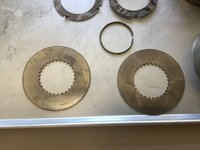
This is made of the following: bushing (12046, only 1), retainer (12555), piston inner seal (12336), piston outer seal (12337), piston (12965), return spring (12975), spring retainer (12985), snap ring (12879), five steels (12126), five frictions (12106), pressure plate (12146), and snap ring (12878*).

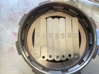
The snap ring can be a wavy ring, or one of the flat selective thickness rings to achieve the desired clutch clearance. All of the books I referenced call for 0.075” - 0.152” for a 5 clutch pack.

Start by greasing the retainer and piston before installing the seals. The lip of the seals point down, the seals have a cross section that resembles a “U”. The open part faces down. Once the seal is on the hub of the retainer and the perimeter of the piston, it is time to gently persuade it to fall into the retainer. Gently pressure while rotating worked for me. Once the seals compress correctly, it just pops in place.
0A92DFCB-1A88-45E1-8252-CF1AEF273DDC.jpeg 2EE70B91-9BA3-4622-B207-A1FEF9DF181E.jpeg

Time to install the return spring. Stack the spring, retainer, and snap ring on the piston. Thread the tool through the center (careful not to hit the bushing). Compress the spring ensuring the “fingers” of the tool do not block the hub and snap ring. Once the groove is exposed, install the snap ring.

FF923A7A-83D4-4E3D-9FCB-515743EC5440.jpeg 8BB49C4E-4922-47EB-8BCE-65AE46E62A16.jpeg 69AB2858-5AC0-470D-8CCE-4BFA1F88778A.jpeg

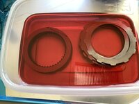
Soak the frictions for 15 minutes or longer, then start stacking in the retainer. Steel 1, friction 1, steel 2, friction 2, steel 3, friction 3, steel 4, friction 4, steel 5, friction 5, pressure plate (pick the best side), finally the snap ring. I used the wavy ring that came with my replacement front retainer. With the wavy ring I measured 0.0930”. Towards the looser side of the specs. I think I will leave it like this. The next ring I have measures 0.075”, and it would cause the pack to have too little clearance. Too tight and the clutch will drag, too loose and you get a sloppy shift.

47010128-15DD-4B54-A744-5A85709C52B1.jpeg BBBCD4B9-909B-4AFD-A157-9A131DAD5AAC.jpeg

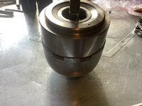
Almost complete gear set, tucked away for reassembly.

2730260E-2949-4397-85DC-E419F6809AC4.jpeg 3DA7D81D-3003-4544-88ED-83A035D0A4CF.jpeg 9C08DD07-DB4F-4A70-885E-6050D0F09C63.jpeg

TTFN
 
Last edited:
After spending some time waiting on parts and doing some varmint hunting (got 3 coyotes and 2 hogs), it is time to get back at it.

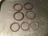
I got some new 12234 thrust washers (#4), they all measured around 0.1225”. Same as the original one, so I am going to run the original. I also got some 12238B thrust washers. 4 were a brass color on one side and silver on the other, 2 were a grey color. All measured around 0.049”. I used 2 of the brass colored thrust washers.

E8497F8C-29EF-4329-A17E-4DD731C6B282.jpeg

Finished stacking the geartrain with the new thrust washers in place.

EC10C3D4-18B4-492E-820F-2E0FD22640BD.jpeg
 
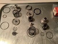
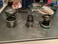
Next up is the servo pistons.

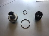
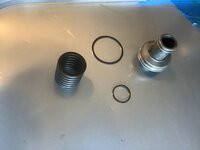
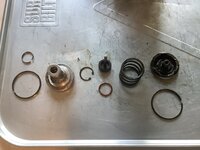
On the kickdown servo, I had to reuse the iron seal rings. None of the iron or Teflon rings in my kit were the right size. All of them were too small and left a large gap between the ends. The o-ring on the piston rod fit and was replaced. The seal rings on the accumulator piston and the low-reverse servo fit just fine.

Reassemble in reverse of disassembly, fairly straightforward.

Low-Reverse Servo disassembled in order of assembly:

D7222D3F-0031-4074-A61A-6A33361D50AD.jpeg

Accumulator Piston:

B70B702B-AA75-425D-BBE7-06EA314A2BE1.jpeg 05C0F4D0-0123-4B89-B603-0E8DC6DB722B.jpeg

Kickdown Servo:

70DA0955-8E91-49C8-A150-9E05E3AFBD2C.jpeg DE9F02E7-35D0-46B1-A110-6D8683B377AD.jpeg

All three side by side disassembled:

6D1C4DBF-60B0-43BC-A7E1-95C5DA5D217B.jpeg

Reassembled and bagged ready for storing until they get reinstalled in the case:

00A5B0F9-5D5D-4DF5-8606-C6C37F0C8556.jpeg 4C353675-5771-43D8-BA5E-0C092E6C8253.jpeg

Next will be the output shaft and governor. TTFN
 
On to the output shaft and governor.

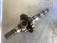
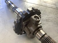
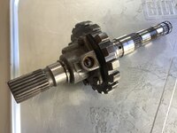
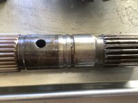
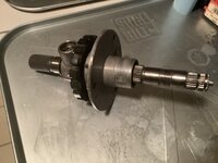
The governor and park gear is held on the output shaft by 2 snap rings and a rod that holds 2 weights. Disassembly is straightforward. Here are the before views.

52E49EA0-C4B0-4C84-99EE-54223DEA2AAB.jpeg C0C35274-F509-4CFE-B3F6-D1E97708C65A.jpeg 5C5B0E99-AC62-4F4E-84F4-69B522621561.jpeg

4DFD957D-DB1A-4945-8CAD-3BC4FD29E73C.jpeg 639E6E95-1BE4-405D-AA7F-D95B40D06636.jpeg 1F0D9EB1-712E-4BB3-B3A2-45A9EC2FE2BE.jpeg

F080F72B-04E9-48B8-907A-AFF5C3441F13.jpeg
 
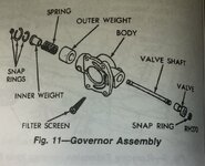
Remove the circlip on the rod and remove the rod. This will allow the small weight to fall out. Then remove the medium snap ring that holds the large weight in the governor body. Then remove the small snap ring that holds the large weight assembly together. There will be an inner and outer weight body with a spring between them.

Next, remove the 4 bolts that hold the governor body to the park gear. Then remove the 2 large snap rings to allow both to slide off the output shaft. Remove the iron sealing rings from the park gear.

Clean and reassemble. The governor assembly is reassembled dry. No grease or oil. It should move freely when dry. I have slipped the case retainer on the output shaft for storage until final assembly.

Diagram of the governor assembly.
F67B8A38-0566-4BF1-8177-0F7D63FCFF5E.jpeg

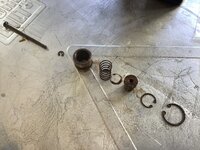
All parts lined up in order of assembly.
4184E217-73AC-4313-A76A-ADA999AA5EDE.jpeg

Parking gear with governor filter in the proper location.
F4C1CE3F-84B8-4669-A347-11F5AB8C5780.jpeg 053ECAB3-34AD-47F7-A5C9-20D4BD956ACF.jpeg

Location of 2 snap rings that hold governor on the output shaft.
4B106729-BAE9-4E23-A833-495FE2CC1167.jpeg

Governor weight in order of assembly.
4DC66E00-DAB0-4C11-888E-00B76CFB8381.jpeg

Final assembly.
B9BE187A-039C-4C3F-8D8C-4044C878367F.jpeg 52DF8F4D-BFF9-4AC0-9E2E-EB2FB8E6B5D9.jpeg 2F10C921-AAE5-4AB8-93F4-524A08C4E03D.jpeg

Next up is the valve body. TTFN
 
Disassemble the valve body, this will be a lot of photos and lots of parts.

To keep track of what screws go where, I took photos of the screws installed before removing them. I then printed the photos and glued them to cardboard or bubble wrap mailers. This keeps the screws captured and ensures the proper length will be installed in the correct location. Many plates have multiple length screws and it is critical to not use a long screw in a short hole. That can permanently damage the valve body.

C2C19F66-3138-41F5-B5AF-0FD2CC0FD1C5.jpeg

99E9369C-B745-43BF-8C36-7D2BD03E95FE.jpeg

3E8C9692-D90D-481E-B2E1-605BD41D35BA.jpeg

7B8B29DC-D7D6-4BEF-9B25-B3B70D7FF6FD.jpeg
 
Last edited:
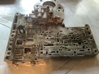
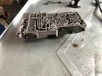
Here are a bunch of valve body photos, no particular order.

54537475-AD29-43BA-ACE9-6F89EC7D6864.jpeg 04A9745E-F6CC-4116-B66D-454A07323746.jpeg 5ABD2FE8-EDA0-451A-AD14-6971320929F2.jpeg 047C6F9C-B4FC-4322-BBC4-8387F517D424.jpeg

632FD1C4-9E13-45ED-B9E3-00BE6D00EF48.jpeg BA3F7E97-850A-4B9D-BD53-FAF9BA558777.jpeg 9BAC4554-A866-464C-AB29-438DE05DB092.jpeg 361D7419-8EBD-496B-B2B0-0FD459363C5E.jpeg

255FD109-0F0F-49A9-8A34-F6D7CF449766.jpeg E4F8BAFC-47AA-4729-85A3-A88D2E3C0980.jpeg
 
Now for some contextual photos.

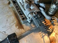
Detent Ball and Spring, this provides the “click, click, click” when shifting.
FC0B8684-9337-4B7A-B335-430CD8CDEC31.jpeg

Manual Lever Assembly / Throttle Lever Assembly, this is both the shifter and the throttle valve lever that increases line pressure as throttle increases to help clamp the clutches tighter under high power situations.
8D657E51-6D6A-4BC9-A4C0-2F9396D13F06.jpeg

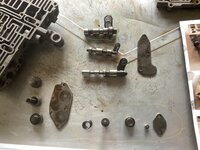
The valve circled in yellow is the Regulator Valve
The valve circled in red is the 1-2 Shift Control Valve
The valve circled in blue is the 1-2 Shift Valve
The valve circled in green is the 2-3 Shift Valve
The valves to the left will be described below
E8CB162A-E632-47B9-B8F0-FE6279410448.jpeg

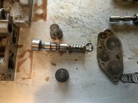
The top spring / valve is the Fail Safe Valve
The bottom spring goes to the Lock-Up Valve that is still inside the housing
BFEC587E-9B87-49CA-AFC6-B5A1A64185E7.jpeg

This is the Lock-Up Valve
0945B042-FE7D-47C0-BA23-DB53001A0063.jpeg

The valve circled in red is the 1-2 Shift Valve Governor Plug
The valve circled in yellow is the Shuttle Valve (note the broken e clip. It broke during removal.)
The valve circled in blue is the 2-3 Shift Valve Governor Plug
5CE83955-8D3B-4F24-8F85-EC3BA1AFA7B9.jpeg

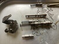
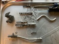
The valve circled in blue (top and bottom combined) is the Throttle & Kickdown Valve
The valve circled in red is the Manual Valve
The valve circled in yellow is the Switch Valve
The valve circled in green is the Line Pressure Regulator Valve
83185903-A625-4A17-B176-F54E38267725.jpeg 3A6E2FF3-600E-4B8C-8C7D-6A7DC5527030.jpeg
 
Here are where all of the check balls locate
758CD430-4F84-4264-909F-D3BF61567C68.jpeg

6 are 1/4” diameter
1 is 11/32” diameter

EDIT, I missed the balls in the other side. Hard to see them, so I circled them. One is incorrect, see second photo for correct location.

31496952-18FD-4A07-84FF-32D2A3CFB646.jpeg 63B2CFC8-6F2B-4366-9D60-79BC1099C3A7.jpeg
 
Last edited:
I bagged all of the valve individually and will clean them one bag at a time. This will ensure the springs and valves are not mixed up.

43B94D40-06E5-44F9-BD85-FAFF4A12D12C.jpeg

TTFN
 
Cleaned up some of the parts. Used a soft bristle brush in the parts washer with mineral spirits.

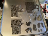
799899F5-229D-4B23-A572-FF4CDEFE8088.jpeg

Then I cleaned up the work space and spread out the valves and other small parts that are sorted in baggies.
2AE85D6F-DB6F-40D7-BB99-49D205509027.jpeg

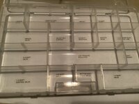
One by one, I made mirror image labels for a storage box. The labels are on the bottom outside of the box. I will use this box to store and sort the clean parts, once they are run through the parts washer.
D278B868-F628-49DA-A6C2-510B4C199B79.jpeg

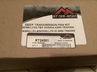
I also recieved a deep pan ordered earlier in the week. Ordered on Amazon. I was concerned for the quality because it was listed as “Crown”. I have found their replacement parts less than satisfactory. But this looks like a quality product. It also does not have Crown anywhere on it or the box it came in.
816CA2BF-4BDD-4021-8BD5-8E3FA0CB6366.jpeg 05054E7E-2272-40E5-9CF8-4D1E34620A84.jpeg

TTFN
 
Last edited:
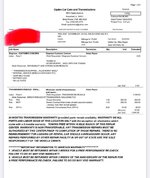
I couldn’t believe this shop turned my jeep around in three or four days, but it cost me a pretty penny! Very jealous of your time, energy, and skills, great work!
 

Attachments

  • 6E189456-A5D6-4899-A86F-6AF8349768F4.jpeg
    6E189456-A5D6-4899-A86F-6AF8349768F4.jpeg
    199.7 KB · Views: 20
  • 9EA22A58-99D0-49E0-AF96-D427F6B00725.jpeg
    9EA22A58-99D0-49E0-AF96-D427F6B00725.jpeg
    151.7 KB · Views: 22
If I was doing this for a living, I am sure I could have it done in half a day. But since this is just for fun, I am taking a long time with breaks in between steps. Also, learning along the way and buying parts. I have not counted my cost, but I am sure I will be well over $500 in parts alone before buying a new TC. I think $1,100 is a good deal for a rebuild.
 
Disassemble the valve body, this will be a lot of photos and lots of parts.

To keep track of what screws go where, I took photos of the screws installed before removing them. I then printed the photos and glued them to cardboard or bubble wrap mailers. This keeps the screws captured and ensures the proper length will be installed in the correct location. Many plates have multiple length screws and it is critical to not use a long screw in a short hole. That can permanently damage the valve body.

View attachment 106375

View attachment 106400

View attachment 106374

View attachment 106373
Luv this idea. I have used cardboard to keep my screws in the proper order but like the picture on top to really make sure they are the right ones in the right place
 
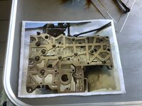
Time to reassemble the valve body. I am not installing the shift kit for now. I want this to be a “stock” build, test how it works, and if I would like firmer shifts then install the kit. Really just eliminating extra variables that could be problems if it does not run right. Plus, pulling the valve body while still in the vehicle is fairly easy.

Reassembly is basically reverse of disassembly, just with more care and lots of lube.

Here are some good illustrations on the various valves. These give you 99% of the information needed to reassemble the valve body, assuming all parts were segregated during disassembly and properly labeled.

472B7268-3FBD-444C-90D3-D552C1A63D77.jpeg 709C113E-853B-494F-9102-02B1001D3664.jpeg

AB3644B5-0C99-44A6-A4C9-9F2029735F79.jpeg D6E78F4F-2867-4557-AFBB-25E5C41654D0.jpeg

Some of the additional items not clearly mentioned are the throttle valve needing to be inserted in the bore before installing the spring retainer and adjusting screw bracket. You cannot get the lever to bypass the screw if it is not installed first. I did not want to move the throttle valve limit screw, so off came the bracket. This is the most difficult part of reassembly because of the strength of the springs and the need to rotate the valve body to access the retaining screws on three sides.

4CAA9E0F-A8A9-45DC-94ED-91D514E0D998.jpeg
 
The next item not widely discussed is the neutral / park insulator on the shift selector. This should be replaced if there is any wear. Plan to replace this as everything I have read and watched indicates there WILL be wear.

06D1BAFE-D618-46A6-B198-81CA429655B9.jpeg 4E1C9D9C-02F6-466B-AEE1-168D650A7574.jpeg 4D8FCEC5-6B70-451E-A062-021F049E143D.jpeg

D4354A9F-D5E2-4AF7-9650-8818BF9CF92D.jpeg 7458063A-8BF2-4F39-9922-D444C5A2961D.jpeg ABA268F3-51D9-4431-9F0B-5E6F748281FE.jpeg

952AD325-C09B-4B7B-A7B7-EF4540DC0544.jpeg 338A7DEB-377B-44CA-898D-9073291A6514.jpeg C81A2CA3-D6BC-4DB3-A9FC-00FC6BFECA11.jpeg

To remove the factory rivet, I gently filed the back side until near the level of the shifter. Once I had most of the deformed portion filed away I used a punch to push it through the insulator and the shifter. The insulator then snaps off. New one snaps on and is secured with a new rivet.
 
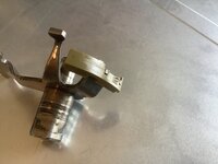
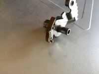
When I removed the shuttle valve during disassembly, the e-clip was broken. I bought several new ones in various sizes from the local big box hardware store. The size that fit best was 5/16”

D5C7FE0B-C9F4-4877-A08D-F02EB08060BB.jpeg

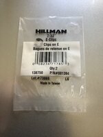
When installing the parking control rod I used a new e-clip, here the 7/32” fit best.

EDDFEBA9-4007-4763-B0F2-5FC12A70C141.jpeg

And finally, one part I did use from the shift kit is the peg used to hold the shift spring and ball while inserting the shift lever. Without this, it would be very difficult to hold the ball back and slide the shift lever into place. With the rod, the shift lever slides down and “pops” the rod away when everything lines up. Easy! One end of the rod is a concave surface that holds the ball, the other is a point that wedges against the valve body.

DC523E9E-2F76-443C-80EC-585A26A9C0FA.jpeg
 
When I replaced the seal for the throttle rod that passes through the shift lever, I used RTV around the perimeter for a better seal.

Only thing left is to install the washer and e-clip on the throttle lever rod. I don’t recall removing a washer, but one is needed due to the potential of the lever fouling the spring retainer bracket without it. So, time to find a suitable washer and install an e-clip. Then it will be time to reassemble everything into the transmission case.

D2366EDC-A28F-45EB-94B2-55B9D1CD00DA.jpeg

TTFN
 
Back
Top