• Notice for iPhone users: DO NOT use the image size reduction option when uploading photos to the forum. This causes portrait images to post as landscape. We have added a warning to the image insert pop-up as well.

Another Scrambler Purchase/Road Trip - UPDATE- BODY ON FRAME AGAIN

Started putting my transfer case back together last night. First pic is of the 2 shafts that have to be placed inside the transfer case in their correct positions, facing the correct way, then the bearings have to be pressed on. The short shaft on the ground outside the transfercase is the input shaft. I had to use the press to press its bearing on.

100_4650-1.jpg


Close up shot of the rear output shaft.

100_4652-1.jpg


Close up shot of the front output shaft.
100_4651-1.jpg


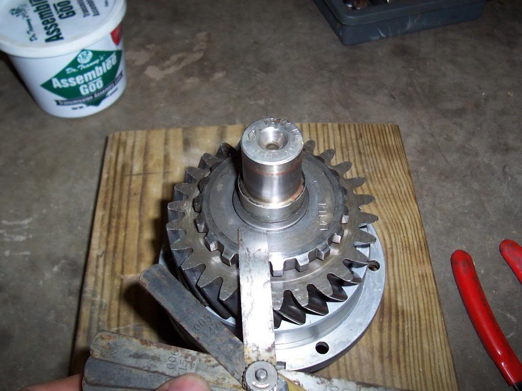
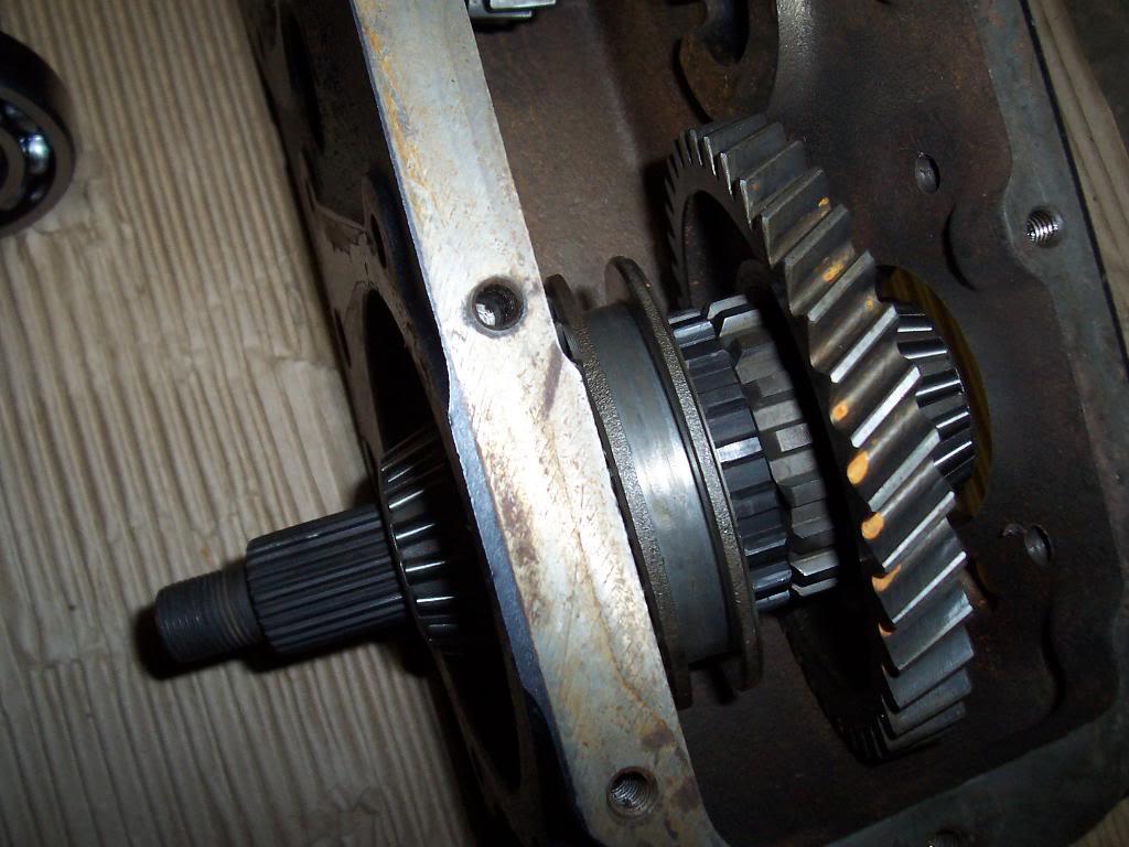
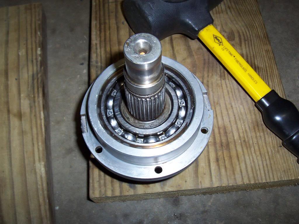
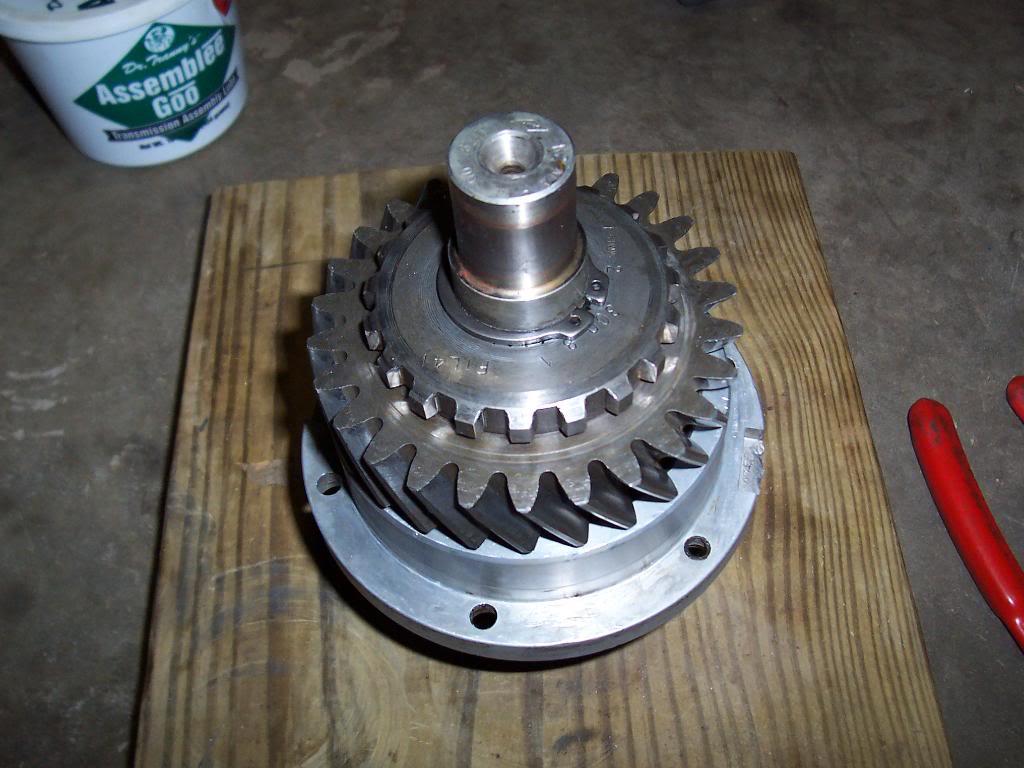
Pics of input shaft assembly. Last pic in this series shows me checking the clearance between the face of the gear and the face of the snap ring (snap ring pushed all the way down inside the machined ridge it rides in). One of the books I have (not the FSM, it makes no reference to this gap) says the gap should be no more then .003. My gap was closer to .004, BUT the face of my snapring does have wear, so I am not worried about being .001 off on this.
100_4653-1.jpg


100_4654-1.jpg


100_4655-1.jpg


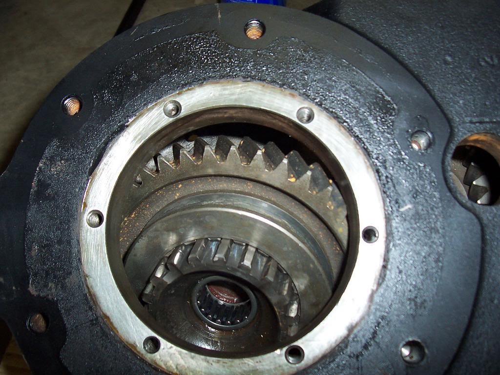
Pics of the anaerobic sealant process.

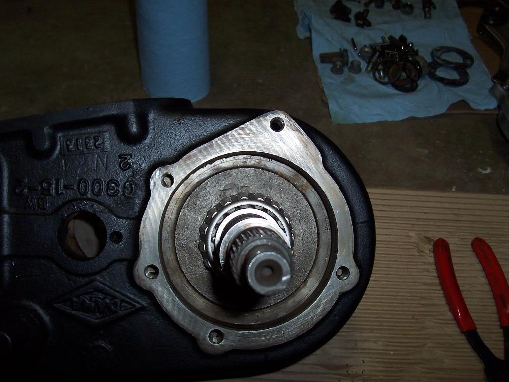
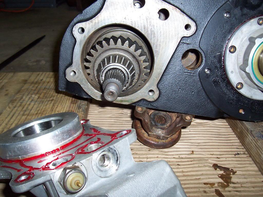
Pic 1, cleaned the face of the transfer case with brake clean, ran a tap through all the threaded holes to clean any gunk off. I then sprayed activator on the machined part of the transfer case, it is clear so it doesnt show up in the pics.
100_4656-1.jpg


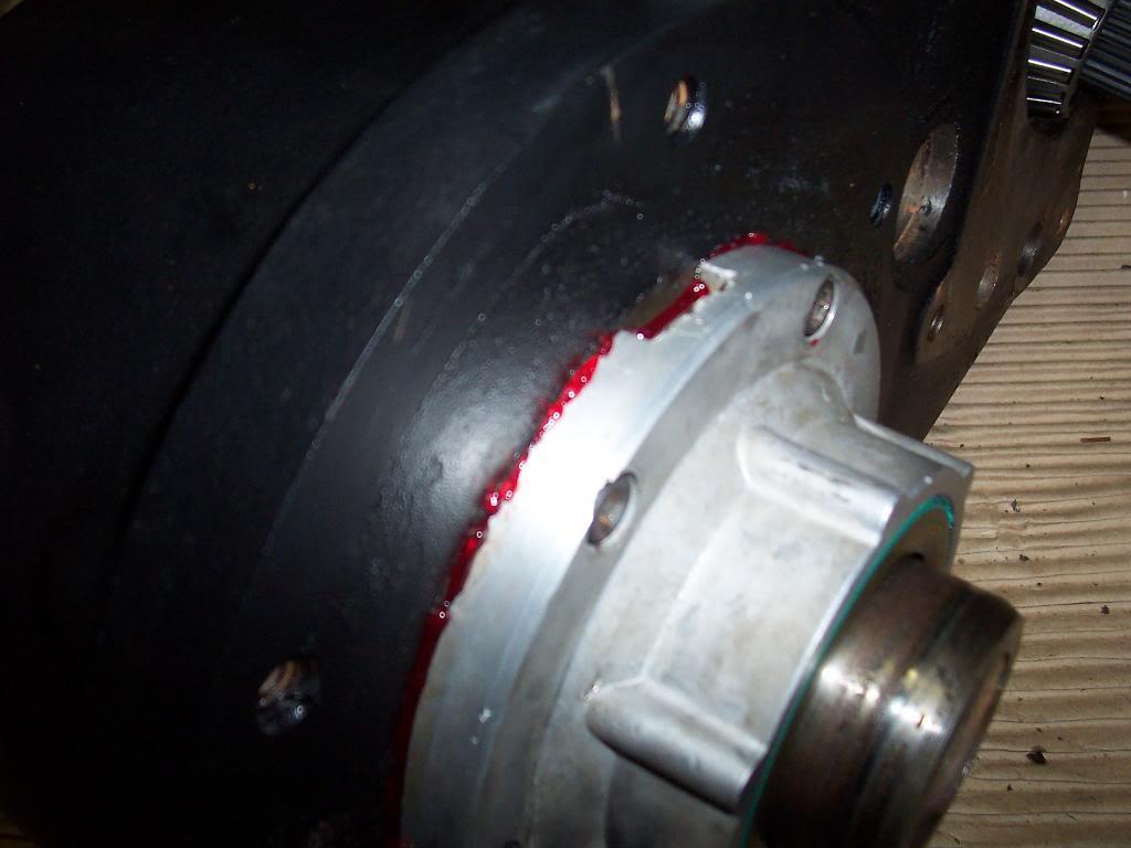
Ran a continuous bead of anaerobic sealant around the input shaft housing. This stuff looks, feels, and smells kind of like red lock tite to me.

100_4657-1.jpg


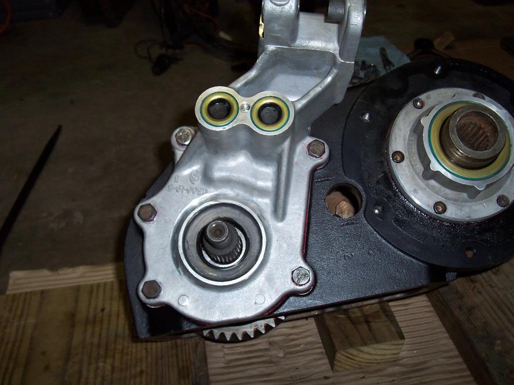
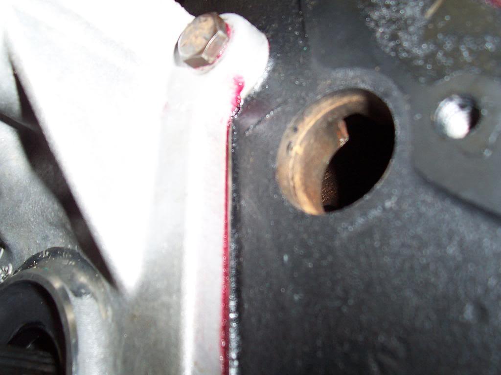
And bolted down. A little bit of excess sealant squeezed out all the way around the input housing, so hopefully it is sealed up.
100_4658-1.jpg
 
Last edited:
Some quick pics of old anaerobic sealant. It shows up as the "bownish" stains on the machined part of the case. It scrapes off fairly easy. Also note the 3 shims in the first pic.

100_4659-1.jpg


100_4661-1.jpg


Got the back of the case cleaned up and ready for the output housing, but I ran out of Lock Tite so I had to stop for the night :-(

100_4662-1.jpg
 
Last edited:
Got the transfer case back together.

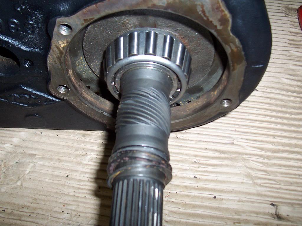
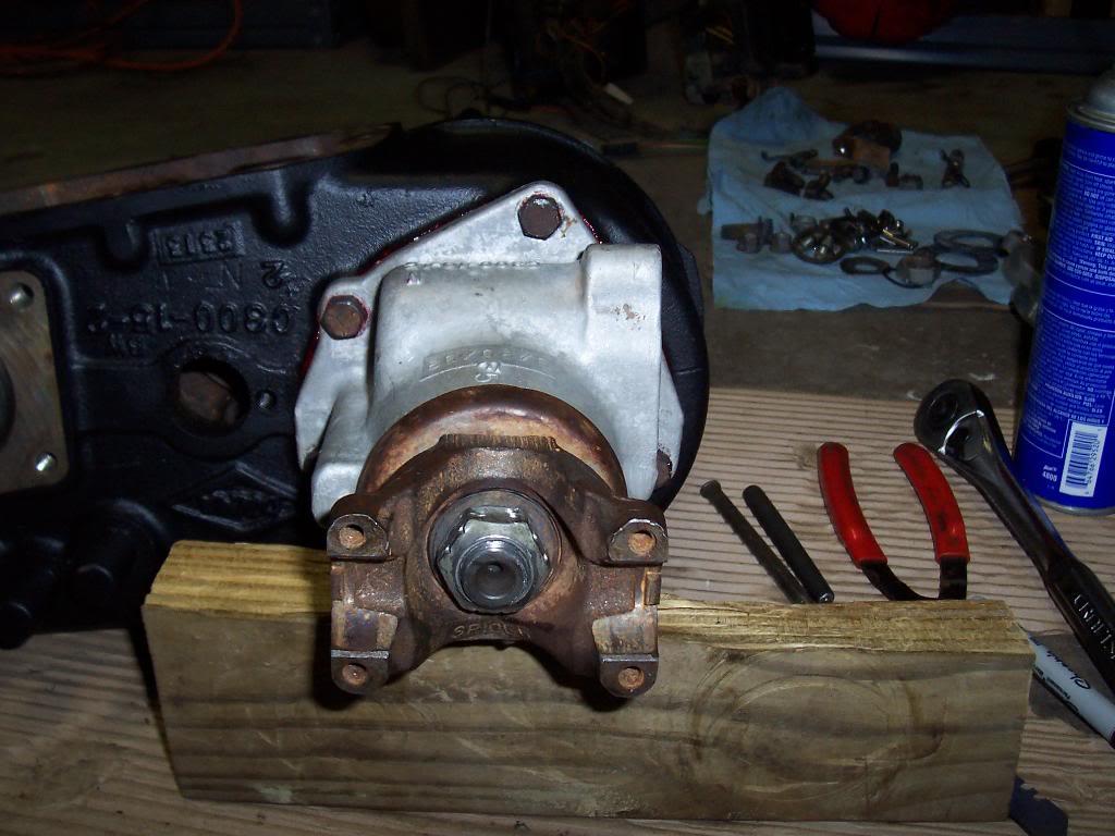
Bolted the rear output housing on. I forgot that you have to use the rear yoke to seat the bearing on the shaft.

100_4665-1.jpg


I managed to damage the seal when I was pulling the yoke off, so I will have to buy a new seal.

100_4666-1.jpg


The reason why I couldnt reuse the yoke I had just bolted on, pic didnt show up clear, but both my yokes have deep grooves cut into them where the old seals cut into them. I ordered new yokes, just dont have them yet. I could have used a speedy sleeve, or simply not drove the seals all the way into the housing so that the seal would ride on an undamaged part of the yoke, but since I plan on driving this a lot I went ahead and bought new yokes.

100_4667-1.jpg


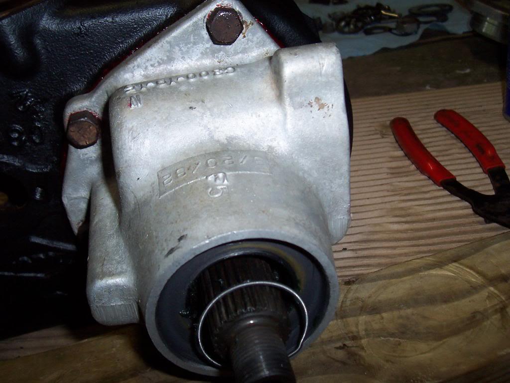
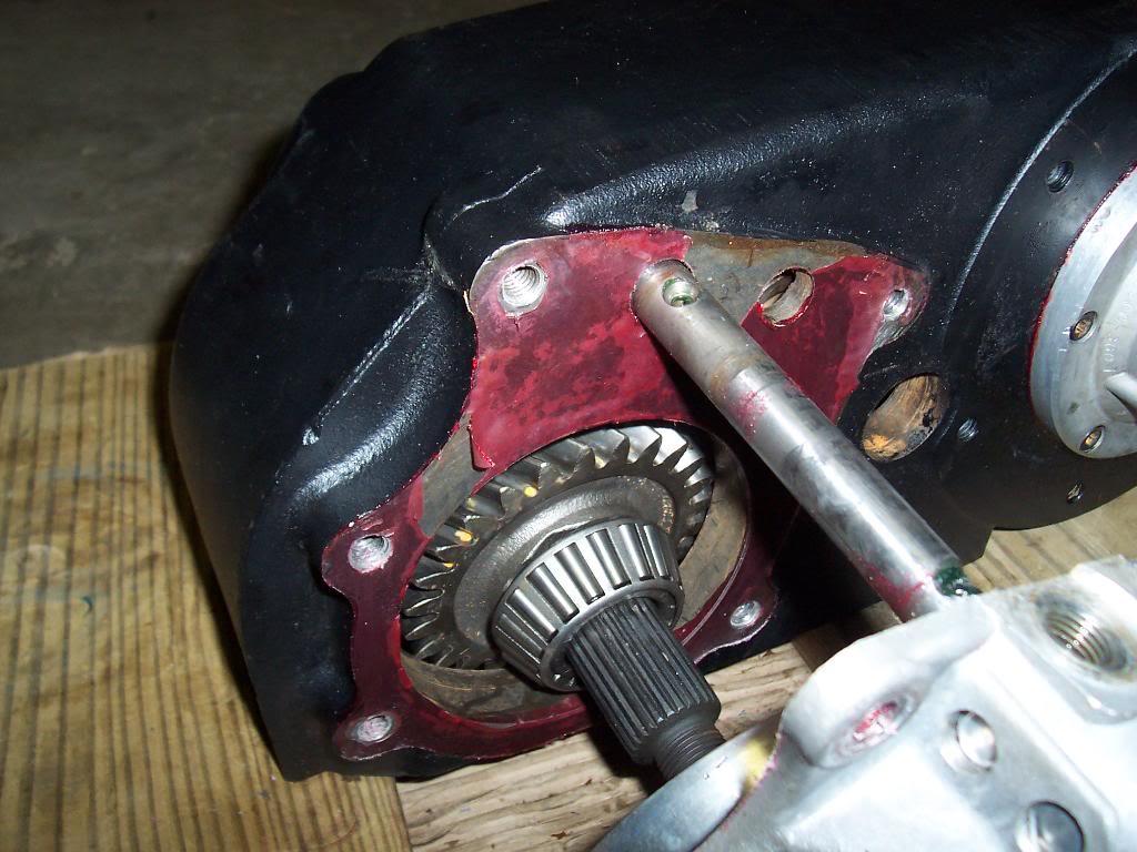
Next I bolted on the front output rear plate thing. I used the stuff pictured to seal it up.

100_4668-1.jpg


100_4669-1.jpg


100_4670-1.jpg


I then bolted on the front output shaft front housing.

100_4671-1.jpg


100_4672-1.jpg


100_4673-1.jpg


100_4674-1.jpg
 
Last edited:
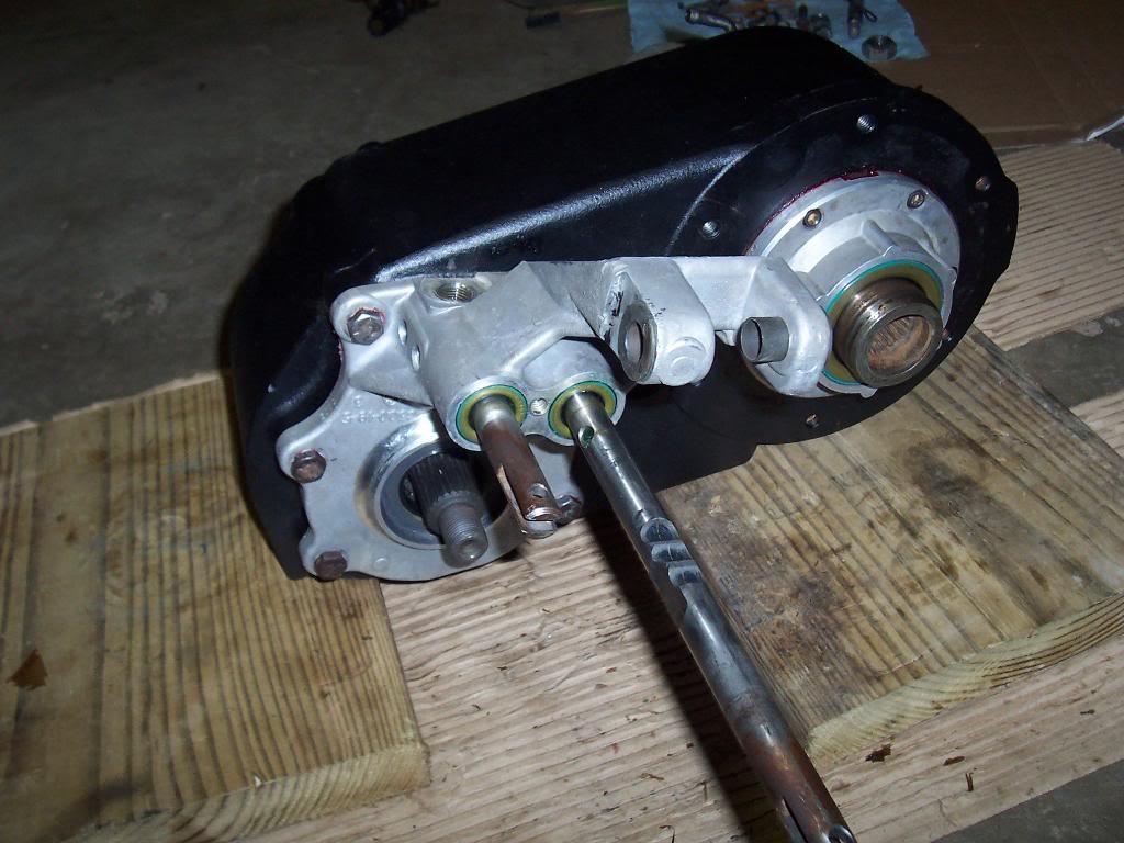
Things were going great until I went to put the shift rails in. I got the first one in no problem, even after the little spring loaded ball flew up ito my face twice LOL. I couldnt get the second one in. I couldnt get the interlock pins to slide over. I "tapped" on it, but still couldnt get it in. This is as far as it would go.

100_4675-1.jpg


My "tapping" managed to get the rod stuck, so I had to pull off the front output shaft front housing so I could tap it back out, which of course meant having to reseal the front shifter housing. The red stuff is the Anaerobic sealant. You can really see how that small bead completely covered the whole thing.

100_4676-1.jpg


I managed to extract the shift rod. I also removed the other one. I cleaned up the housing and bolted it back on. I realized why i couldnt get the rod in. I didnt have the first one all the way in. I had it "pushed" in all the way, but it took a light tap to get the rail to pop over the ball and go all the way in. Once all the way in, all the interlock pins could slide out the way and allow the second shift rail to go into place. So I learned a lesson, make sure the first rail is in all the way before attempting to insert the second rail. And, dont beat on the rails, you can damage the rails and the interlock pins, luckily I didnt damage mine. If they dont slide in, something isnt right. Pics.

100_4677-1.jpg


100_4678-1.jpg


Put red lock tite on the set screws and locked the shift forks to the above mentioned rails.

100_4679-1.jpg


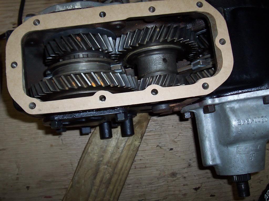
Next I installed the intermediate gear. I slid the big rod in enough to hold the back thrust washer in place. I used a socket to holld the front thrust washer in place. I then lightly tapped the rod into the idler gear. No real problems.

100_4680-1.jpg


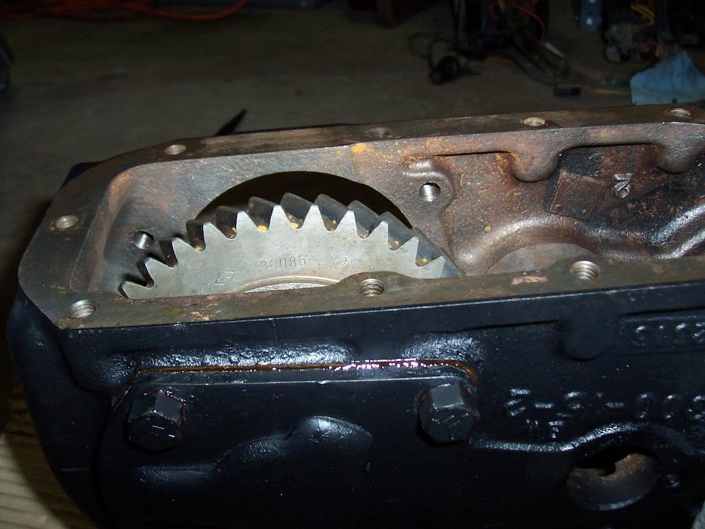
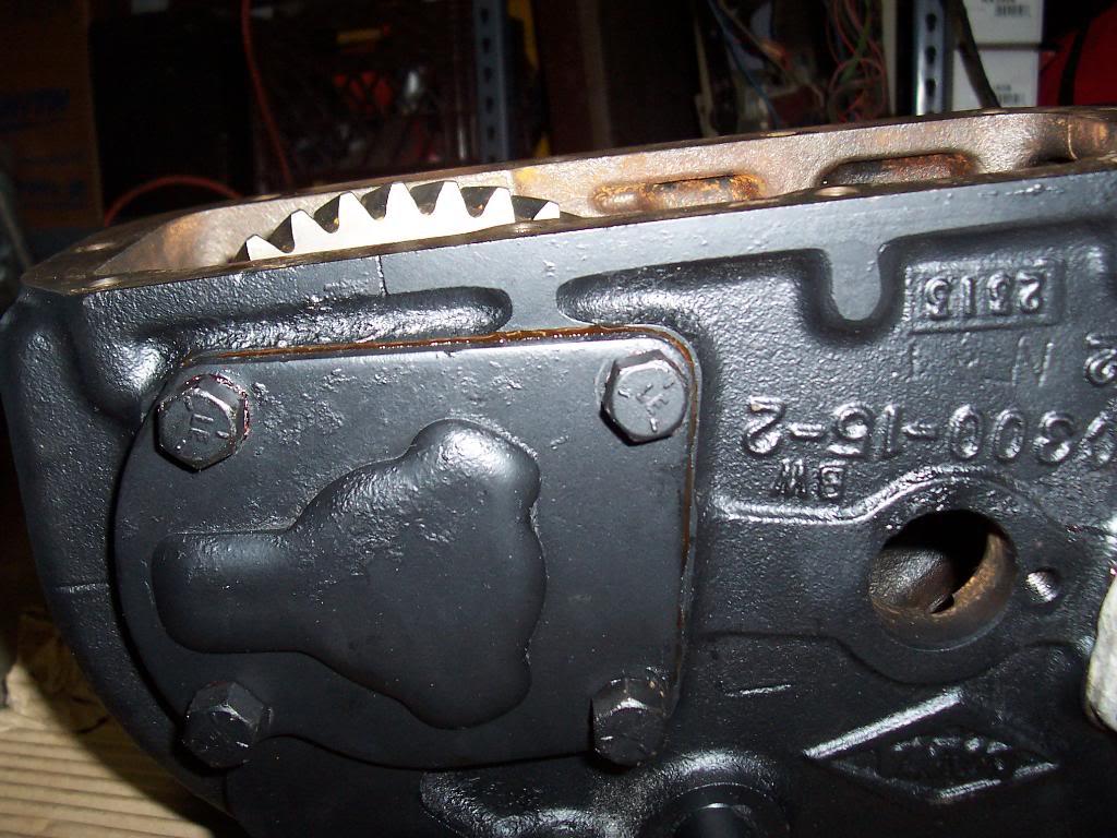
Bolted the inspection cover on.

100_4681-1.jpg


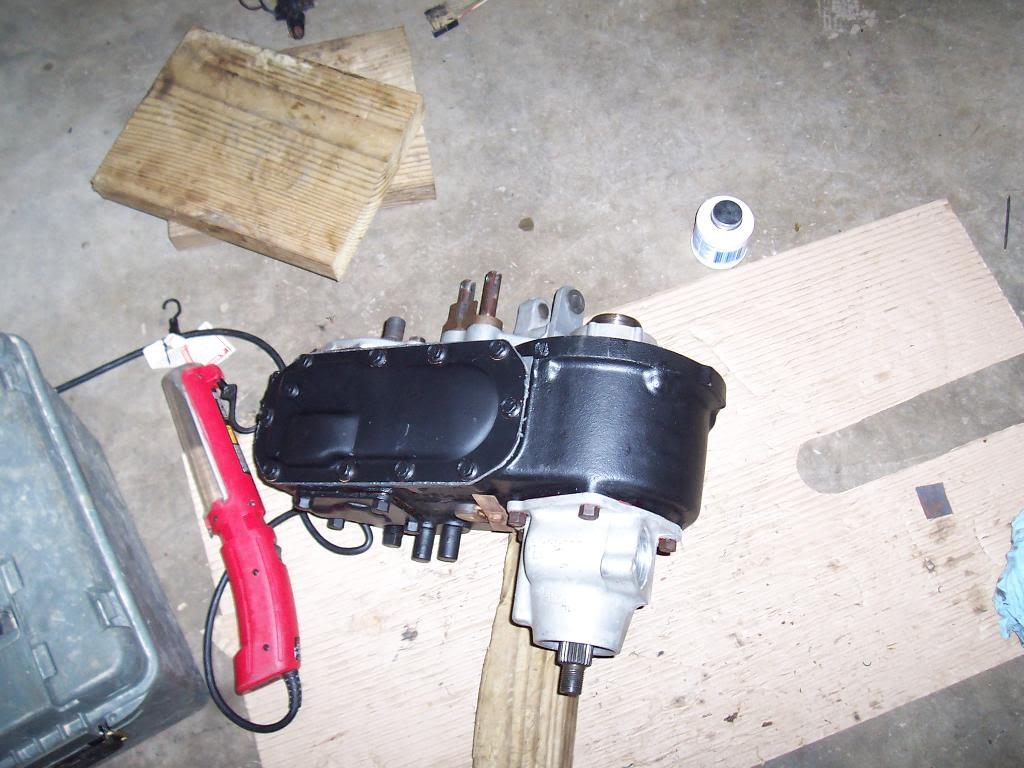
And voila, finished transfer case. The only thing left to do is to bolt on my two new yokes when they come in.

100_4683-1.jpg
 
Last edited:
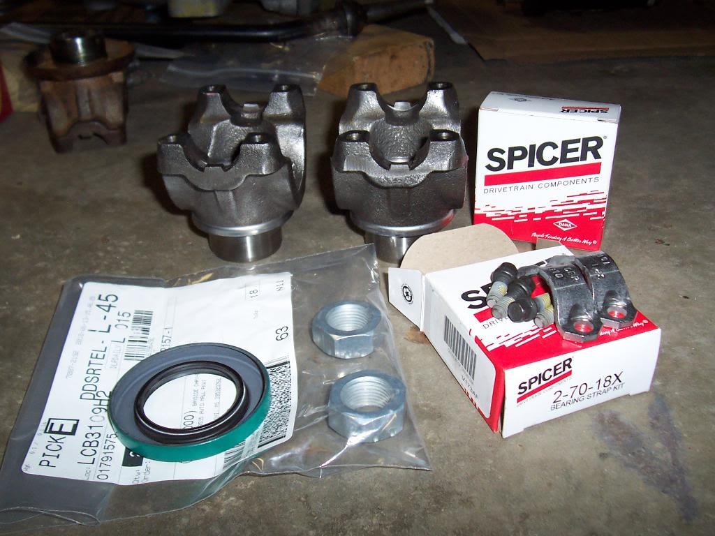
Got my two new yokes, new rear seal, and two new yoke strap kits the other day.

100_4692-1.jpg


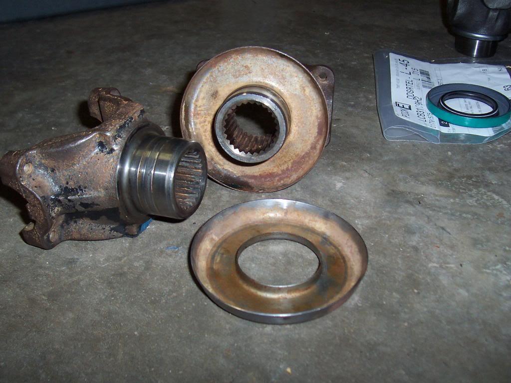
You can see the grooves in this pic. I also got bored and removed the dust shield from one of the old yokes.

100_4696-1.jpg


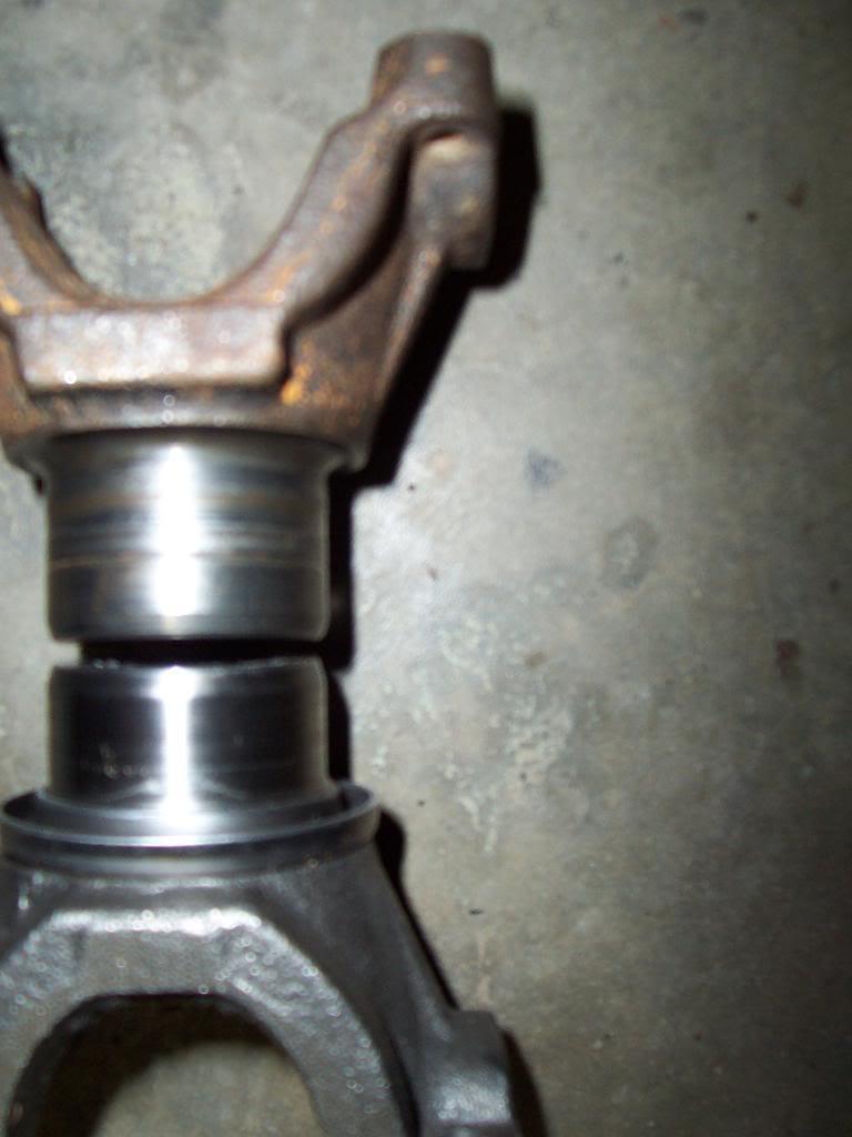
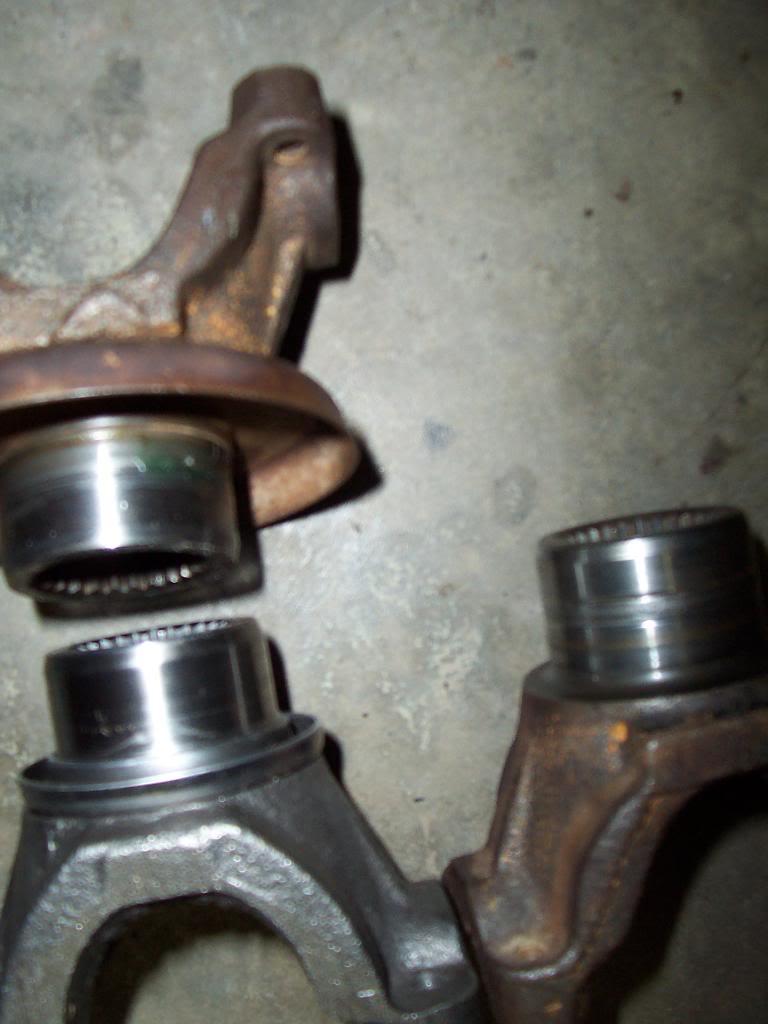
I was going to put these dust shields on the new yokes, but the new yokes are slightly different then the old yokes, so it wouldnt work. You can see in the pics how the machined part of the yoke that rides on the seal is shorter on the new yoke. When you remove the dust shield off an old yoke, the machined part is super long. But, both machined parts are the same lenght where it matters, i.e. lenght from nose of yoke to end of machined part or dust shield. Pics explain it better.

100_4693-1.jpg


100_4694-1.jpg


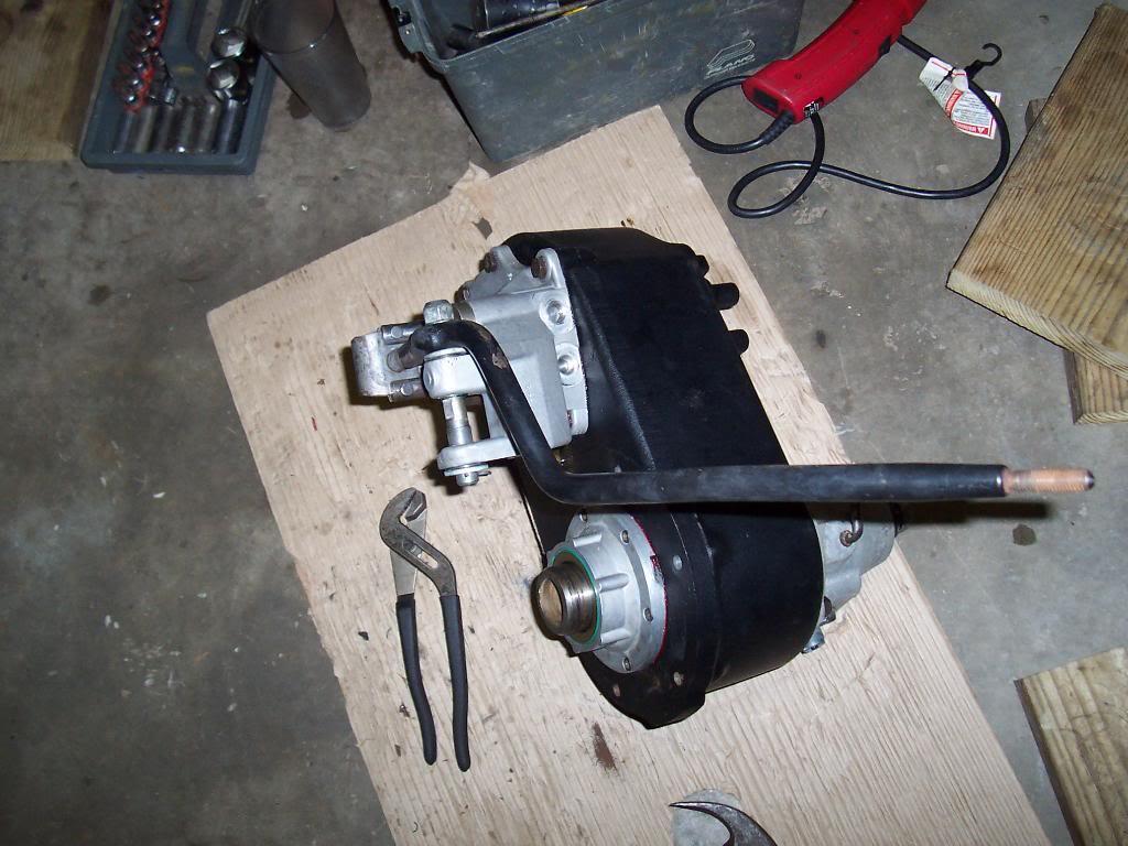
And voila, transfer case is done. According to an exploded diagram from the dealer, my shifter is missing a rubber gromet thing (Crown lists it as the same part # as a shock bushing) at the bottom of the shifter handle, where the shifter handle meets the plate piece that connects to the two shift rails. I have no idea what this rubber piece would do, except maybe lessen metallic noise if the shifter linkage was really wore out and vibrating alot?

100_4697-1.jpg


I also started taking some stuff off of my motor. I am just going to clean the motor up and repaint it, not rebuilding it at this time. This motor runs great, holds excellent oil pressure, has plenty of power, etc.

100_4684-1.jpg


100_4689-1.jpg


As you can see, the internal parts of the motor are very clean, no sludge or any other kind of junk.

100_4685-1.jpg


100_4686-1.jpg


100_4688-1.jpg


The only engine work I am doing at this time:

Aluminum Valve cover to replace factory plastic one (have to retap 5 holes from 1/4" to 5/16")
New oil pan gasket (Got a Fel Pro 1 piece gasket from NAPA, 1 piece vs the 4 piece stock gasket)
New timing Chainm cover gasket and front seal
Install new harmonic balancer (for my future install of the Mopar MPI kit)
New Intake and Exhaust manifold gaskets
New Fuel Pump gasket
Fresh coat of semi gloss black paint on the head, block, and oil pan

I am going to initially reinstall my 6 cylinder with the factory ignition and carb. Once I get the Scrambler back up and running for awhile (to make sure i dont have any issues with any of my other work), I will pull it back in the garage and install the fuel injection. I dont want to have too much new stuff going on at 1 time, it will make it a little easier for me to troubleshoot any probs if I just have the factory carb and igniton installed.
 
Last edited:
More engine tear down pics.

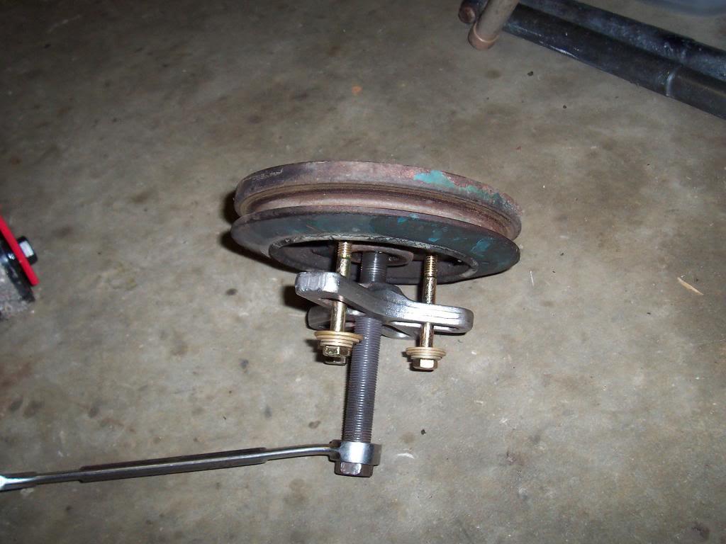
Pulled the harmonic balancer.

100_4701-1.jpg


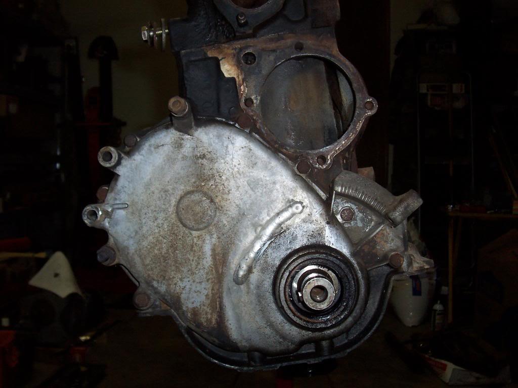
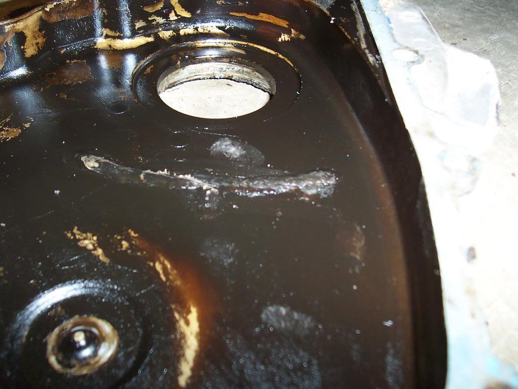
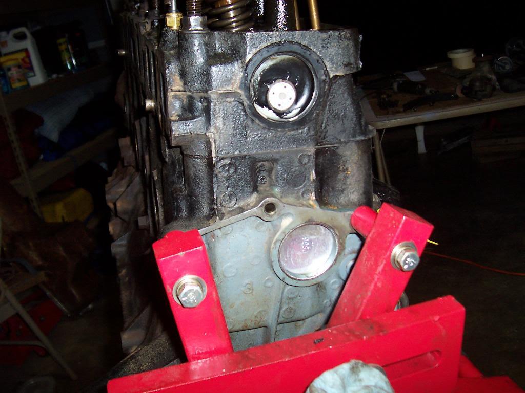
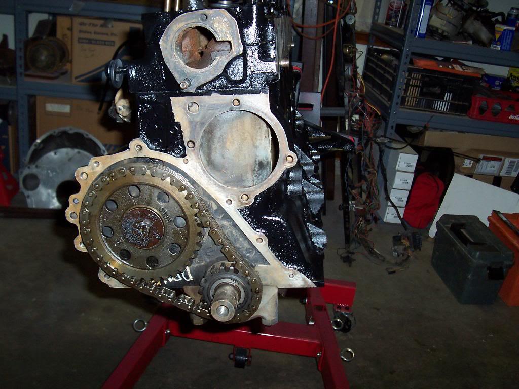
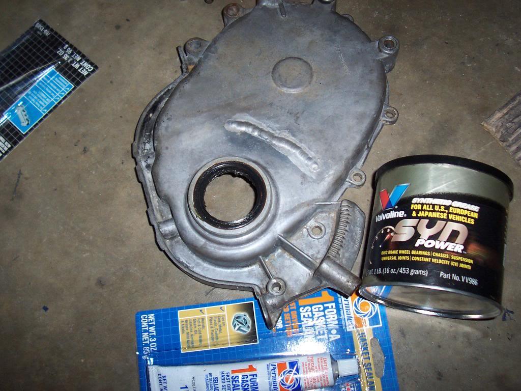
At some point in this jeeps life the engine must have had a catastrophic timing chain failure. You can see where someone welded up a large hole that was present in the face of the timing chain cover. There is a smaller repaired hole in the side, too. This cover does not leak, so I will reuse it. The repairs add character. I am missing the oil slinger that goes between the cover and the crank gear.

100_4700-1.jpg


100_4702-1.jpg


100_4704-1.jpg


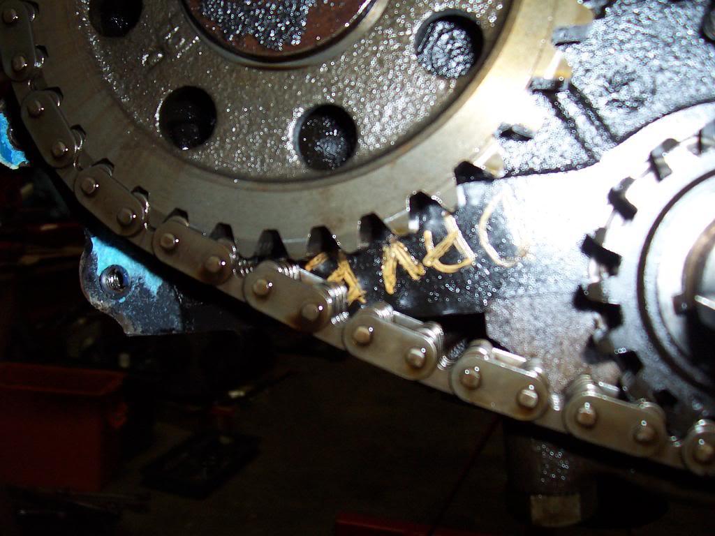
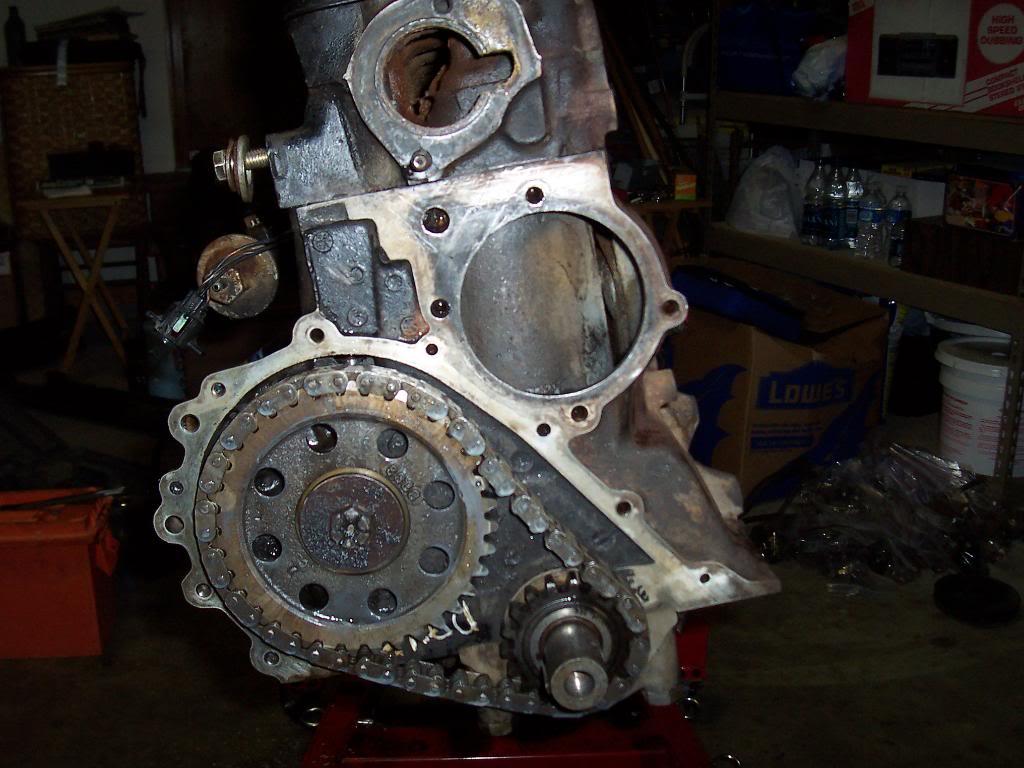
I guess "Dave" built this motor LOL. I figured this was a rebuild. I think this is actually a 1982 block and head. I will have to look up the build codes on the block and head to nail this theory down. I always thought this was a swapped in motor due to the short dipstick tube vs my other 83's long tube. I checked the deflection in the timing chain. Book says if it has 1/2" or more to replace. My chain deflects about 3/16" inch, so it is good to go.

100_4705-1.jpg


100_4706-1.jpg


Tapped the 5 holes in the cylinder head for the new valve cover. The two existing holes on the driver side had never been tapped. They tapped easy enough. The 3 holes on the passenger side had 1/4" helicoils inserted into the stock 5/16" holes. I removed the helicoils and was able to salvage the existing 5/16" factory threads.

100_4707-1.jpg


100_4711-1.jpg


100_4708-1.jpg


100_4709-1.jpg
 
Last edited:
Love how thorough you are with the thread and pics :bow:

Appreciate it bigwalton:thumbsup:

I figure I might as well take some pics along the way. I know some of the details are mundane, but thats what makes every jeep build unique:) Maybe some of this info will be helpful for others, too:shrug:
 
You get alot of work done. Keep it up. Mine feels slow....

Just for you, I didnt work on my Scrambler this weekend, so you wouldnt feel bad LOL:thumbsup:

Helped a buddy do a shackle reversal on a highly modified YJ, 5 hour task turned into 10:30 in the morning to 12:30 Saturday night:eek:

Took Sunday off:)
 
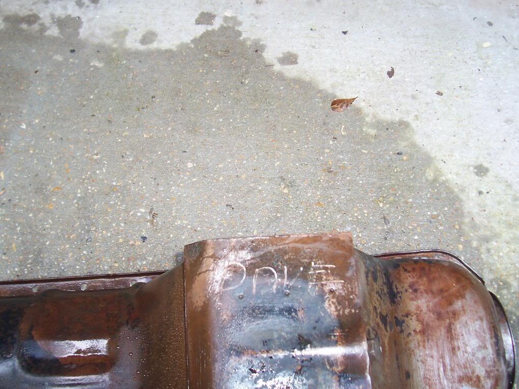
Just who exactly is "Dave"? Hopefully he is a master engine rebuilder. His name showed up on the bottom of the oil pan. He must be proud of his work :-)

100_4712-1.jpg


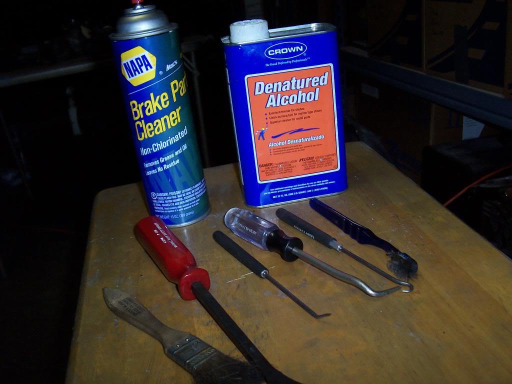
More engine cleaning. Fun. Tools of the trade.

100_4717-1.jpg


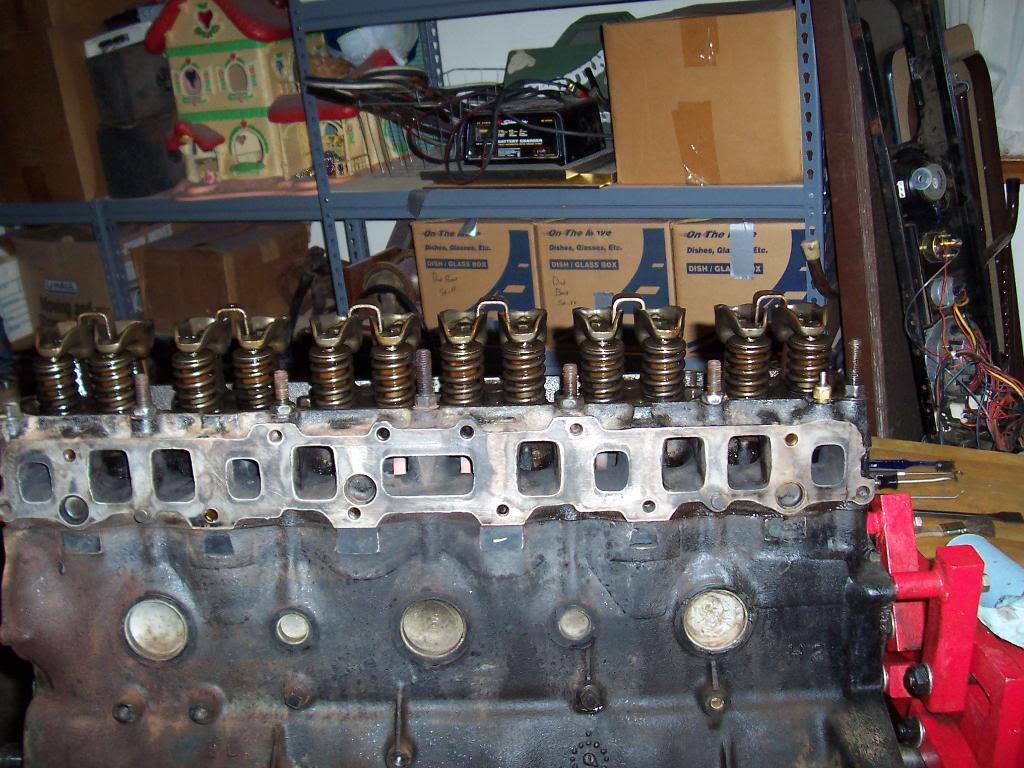
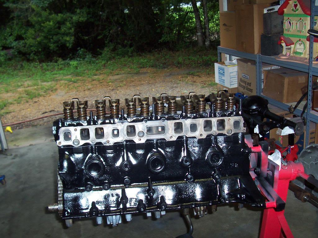
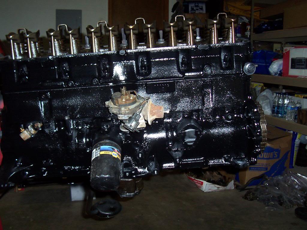
Quick pics of cleaned up engine. Still have a little bit more to clean on the front. Then masking tape, then prime, then paint. And NO, you cant have my Strawberry Shortcake house that is in the background of the first pic LOL.


100_4713-1.jpg


100_4714-1.jpg


100_4718-1.jpg


100_4719-1.jpg


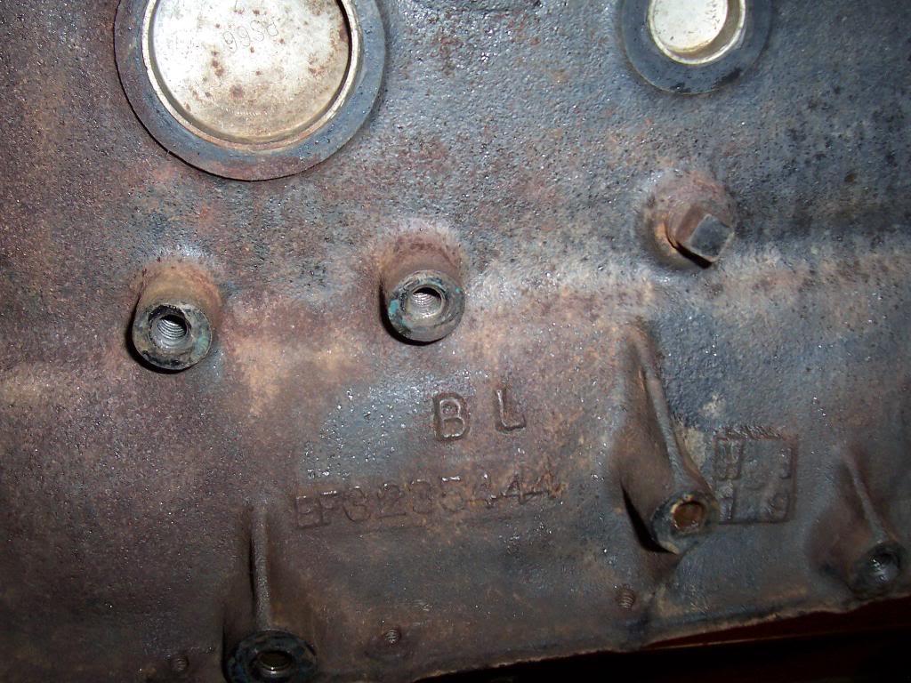
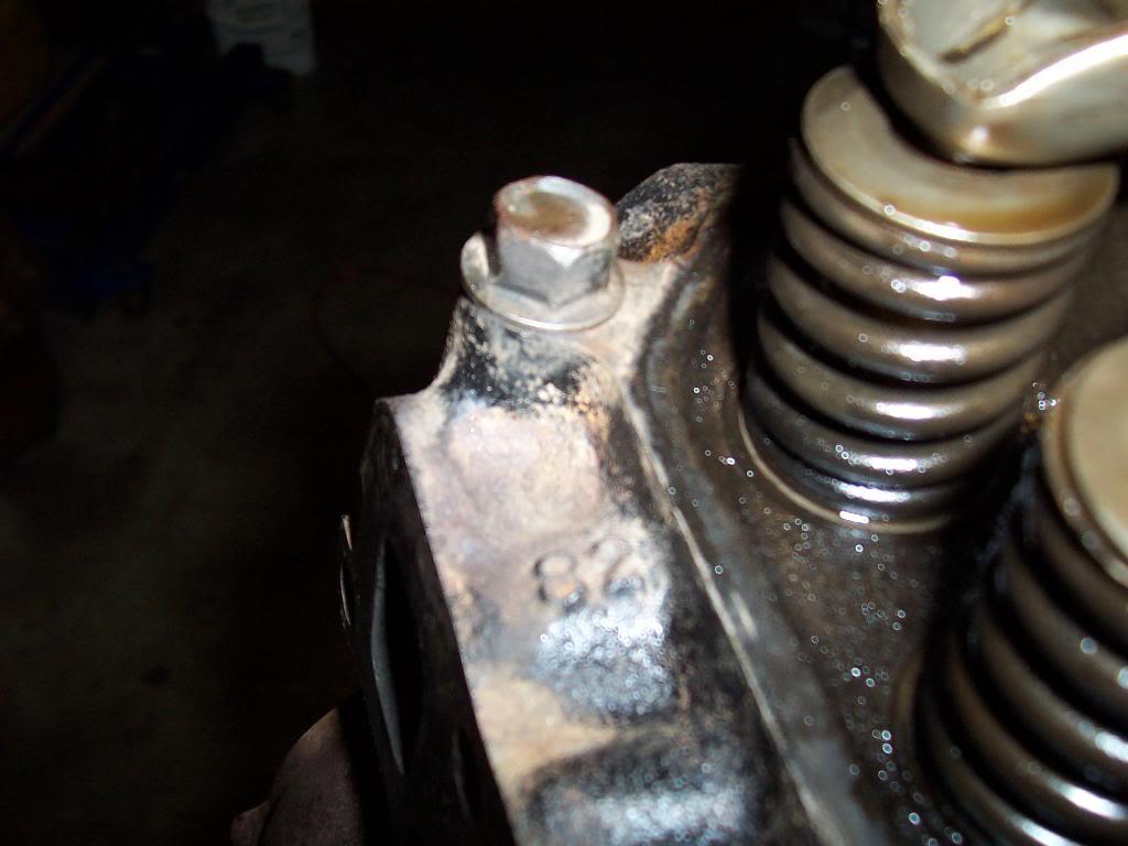
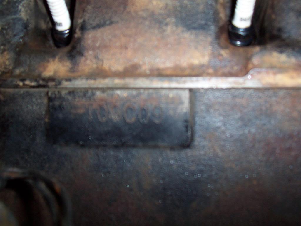
Engine code info. First pic shows a bunch of numbers, I didn't look them up. Second pic shows an "82" stamped in the head. I don't know if this means anything. Last pic shows the stamped factory build code. It didn't show up well in the pic, but the code is 109C09, which translates:

1=1981
09= September
C=258, 2 barrel, 8.something compression ratio
09= 9th day of the month of September.

So, basically I have a 2 barrel equipped 258 that was originally built September 9, 1981.

100_4715-1.jpg


100_4716-1.jpg


100_4720-1.jpg
 
Last edited:
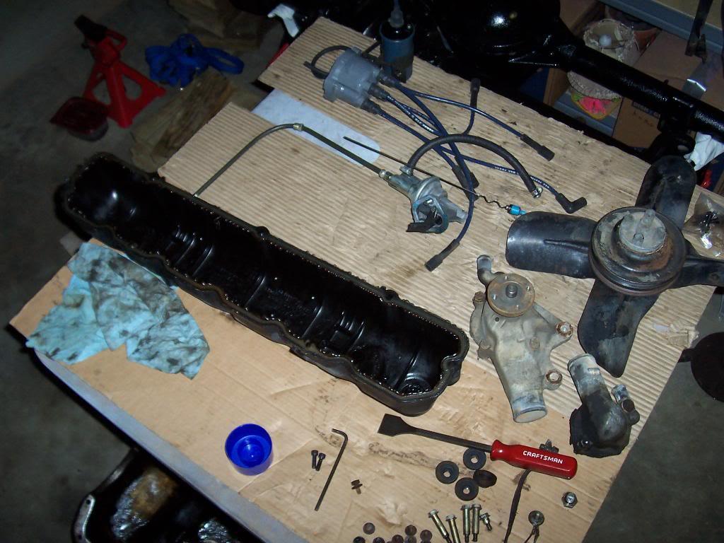
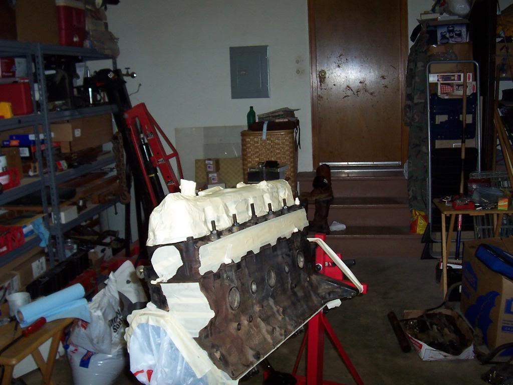
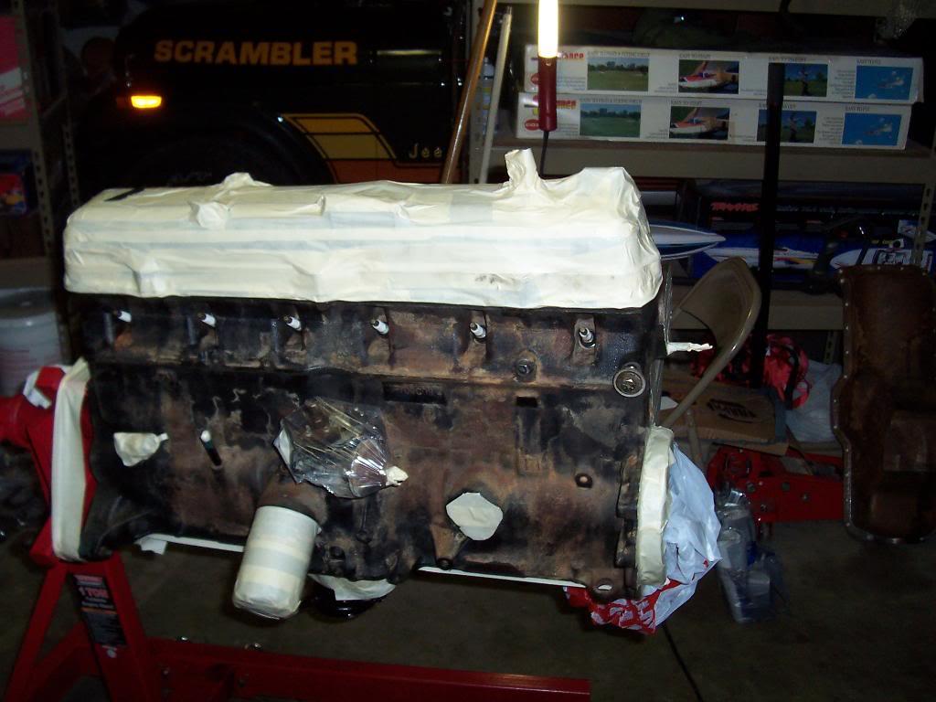
Finally finished cleaning the engine and oil pan. Got them all masked up.

100_4721-1.jpg


100_4722-1.jpg


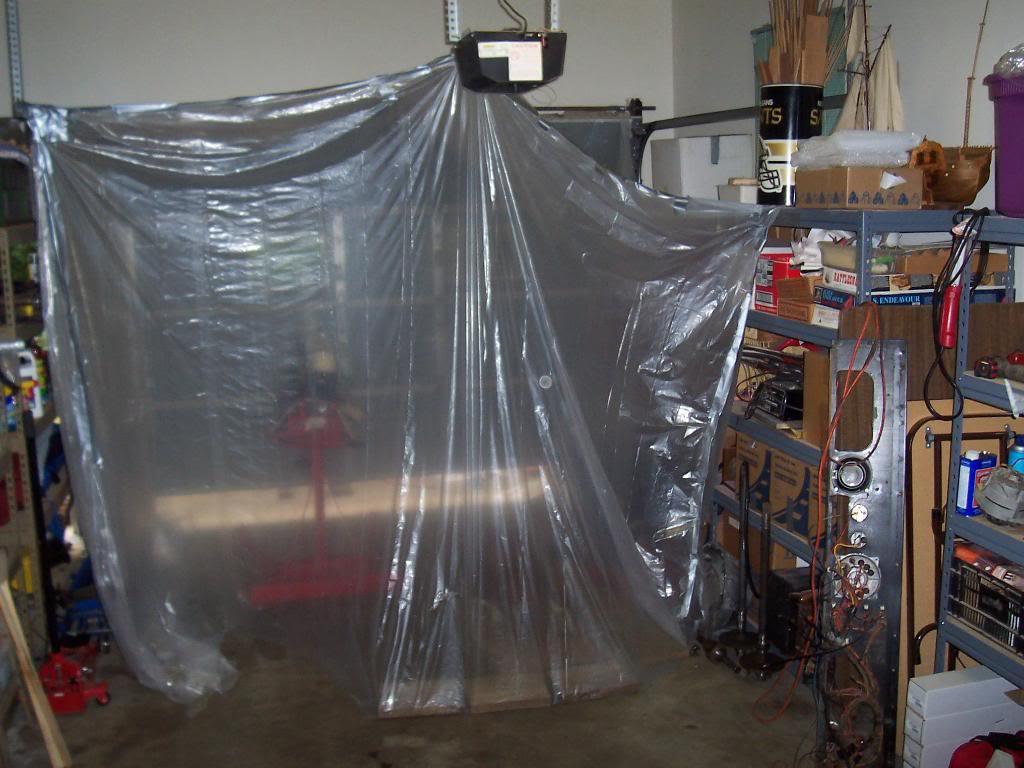
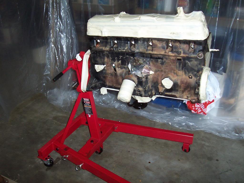
Since I couldnt push the engine out in my gravel driveway to paint, I built a "paint booth" in the garage. Main reason for the "paint booth" was to keep all the overspray contained in one place.

100_4724-1.jpg


100_4726-1.jpg


100_4727-1.jpg


Coat of primer.

100_4728-1.jpg


100_4730-1.jpg


100_4731-1.jpg
 
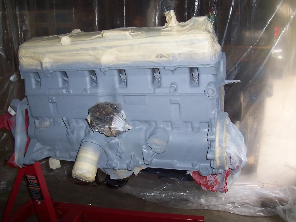
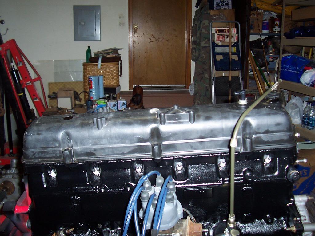
And some pics of painted engine. Came out pretty good. I used Dupli Color Engine Primer and Paint. 1 can of primer, 2 cans of paint. About 16 hours of cleaning and prep, about 1 hour to paint LOL

100_4732-1.jpg


100_4733-1.jpg


100_4734-1.jpg


100_4735-1.jpg


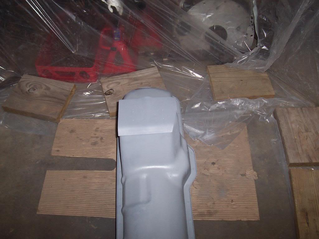
The oil pan has some "greyish/faded spots" showing up. I think that is because I was trying to use up the rest of the can and ended up spraying a concentrated mix of pure accelerant onto the wet paint. Might recoat it once this coat cures (7 days curing time is what it said on the can prior to recoat)

100_4736-1.jpg


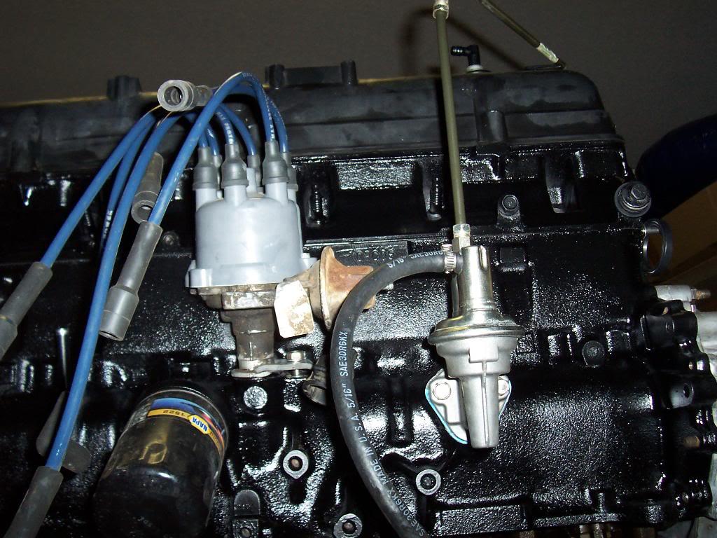
And started reassembling engine. Just the fuel pump and distributor hold down. If you look close you can see the Totally Stainless SS bolts LOL

100_4737-1.jpg
 
Great pics. Engine looks great. I did not see your name ecthed into the engine anywhere? You should be "proud" of your work as well. Not just Dave.

Dain
 
Great pics. Engine looks great. I did not see your name ecthed into the engine anywhere? You should be "proud" of your work as well. Not just Dave.

Dain

If I would have actually rebuilt the engine (pistons, rods, crank, cam, bearings, head, valves, etc) I would have signed it. I will just sign the whole jeep somewhere:thumbsup:
 
More engine assembly.

Installed the front seal in the timing chain cover. Used the hard sealer stuff around the outside, put a layer of grease on the seal lip to protect during initial start up.

100_4738-1.jpg


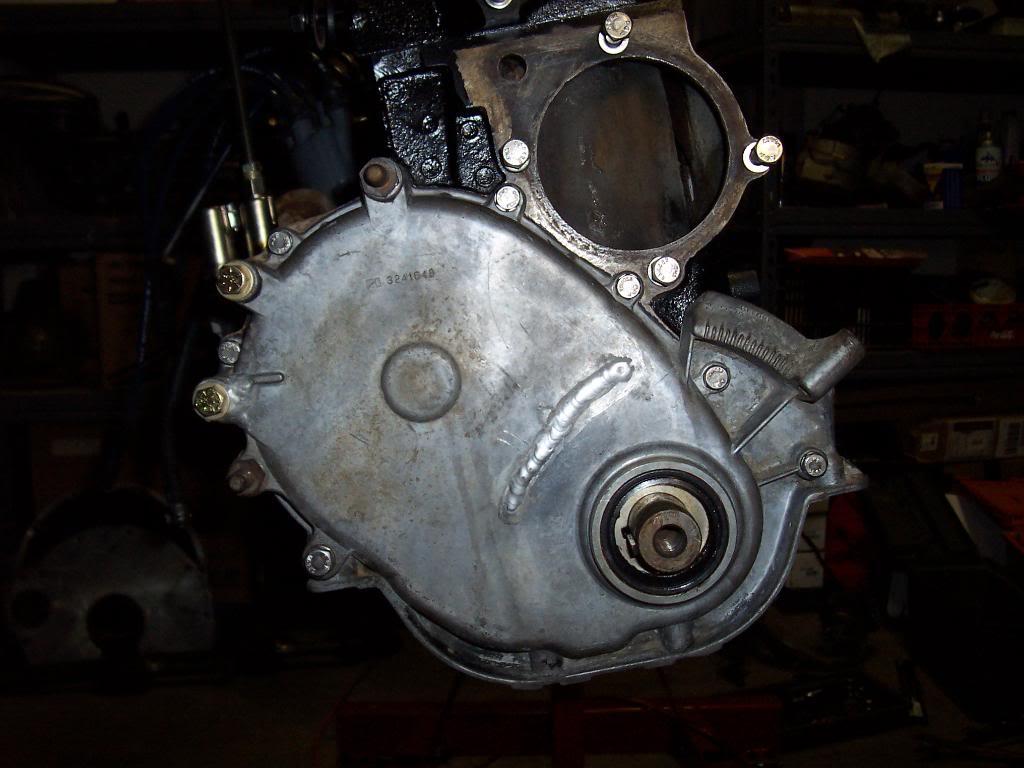
Snugged the cover up, but not fully tight. Left it a hair loose until after I installed the harmonic balancer, to ensure that the balancer hub passed through the exact center of the front seal, not off center where it would ride on the seal uneven. This might be unnecessary, I checked the clearance between the face of the seal and the crank with the cover snugged down, and it had uniform clearance, within a 100th of an inch.

100_4739-1.jpg


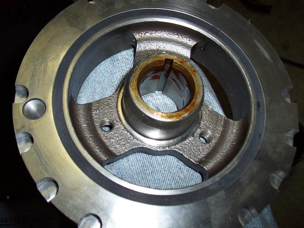
Used brush on sealant inside the harmonic balancer hub to keep oil from seeping out between the crank/hub interface. This is a super tight fit, but just extra insurance. Fixing a leak here after the motor is installed will not be fun. Ran a thin layer of grease around the outer hub portion of the harmonic balancer to help protect the seal.

100_4740-1.jpg


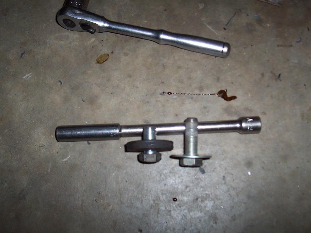
The short bolt is the factory attaching bolt, with the thick washer. The longer bolt, with the thin washer, is one that I used to pull the harmonic balancer onto the crank with. It pulled it on with no problems, way better then "driving" the balancer on with a hammer. Need to get a new, longer crank bolt and washer, basically just the same size bolt that is a little longer then stock and grade 8. It is amazing that a $220 harmonic balancer can't come with a new bolt.

100_4741-1.jpg


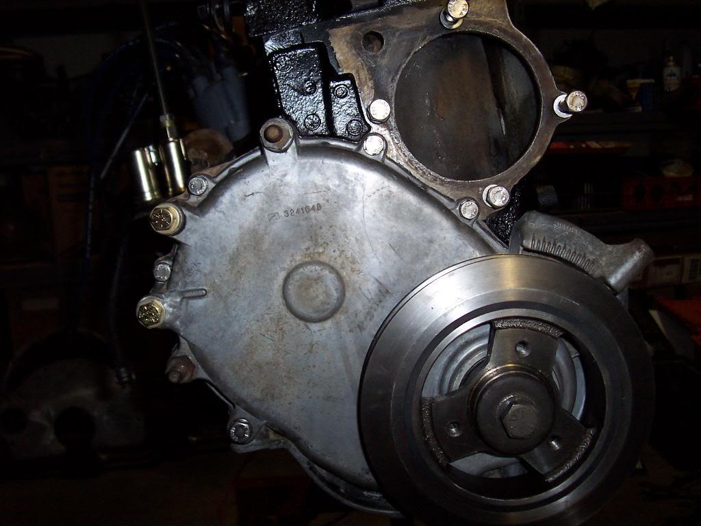
And a pic of the installed harmonic balancer. This is a new balancer, required for the Mopar Fuel Injection, that is why it is all bright and shiney. It is designed to work with the kit supplied crank positioning sensor. I am not installing the entire injection kit yet, just certain pieces that are easy to install at this time and that will work with the factory carb/ignition.

100_4742-1.jpg


Changed out the old spark plugs for new ones. I left the old ones installed in the head when I was painting, thats why the old ones are black in some of the previous pics.

100_4743-1.jpg


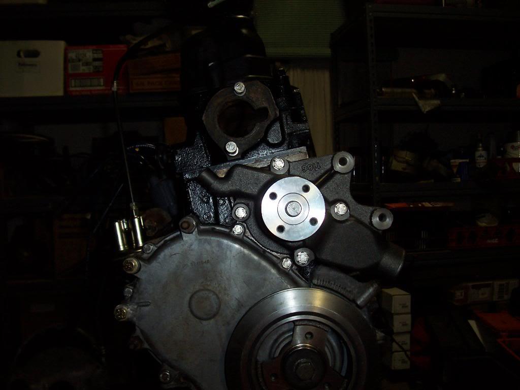
Installed a new water pump.

100_4744-1.jpg


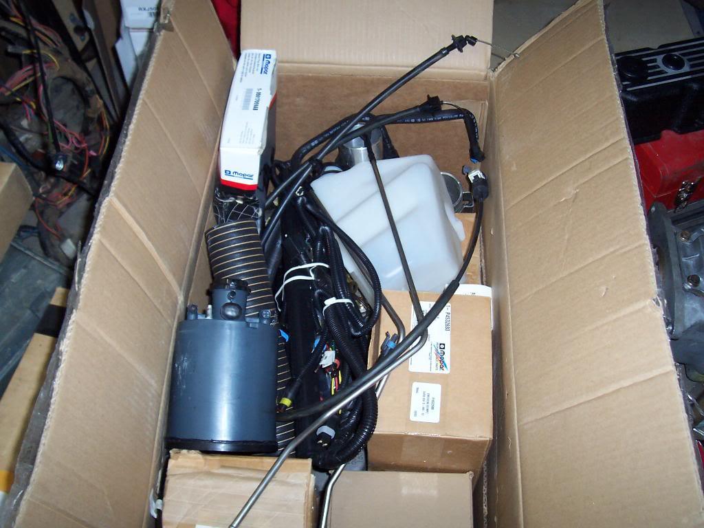
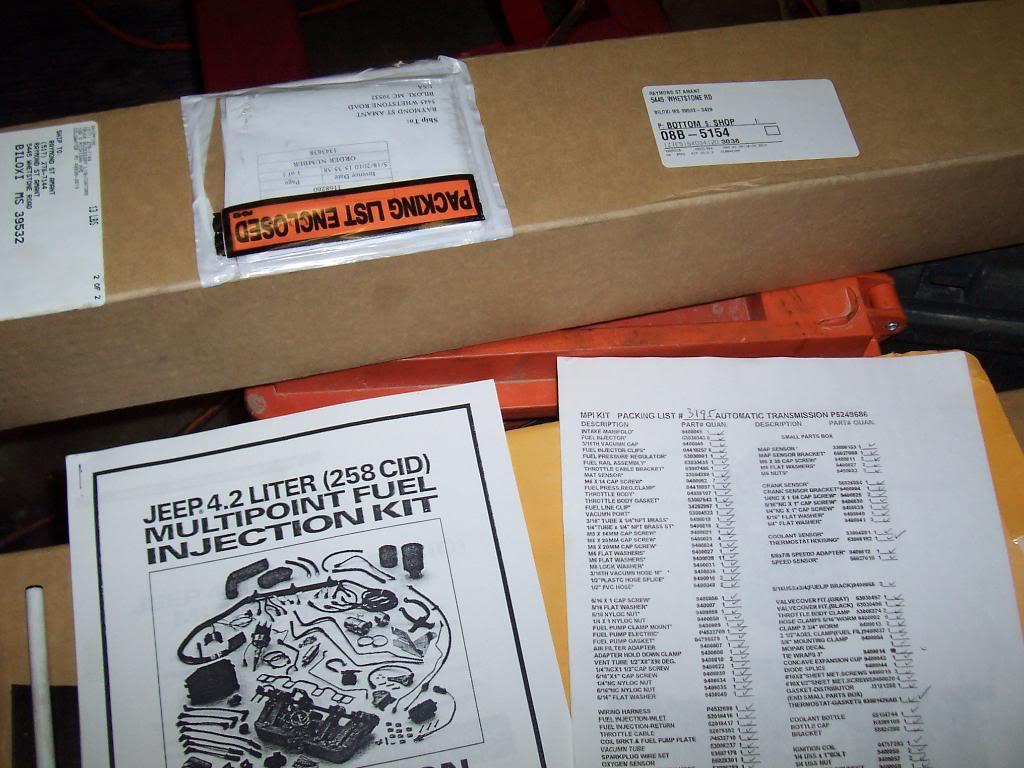
Quick pick of my box full of fuel injection kit. I had to dig in here to get the new thermostat housing that is used with the MPI kit.

100_4745-1.jpg


100_4746-1.jpg


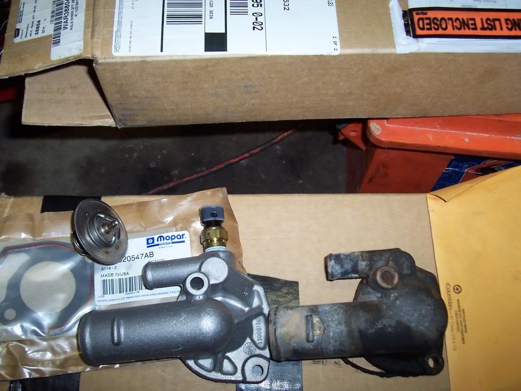
Pick of the new vs old thermostat housing. The new one has a temp sensor built into it, and its shiney and new. MPI kit also came with a 195 degree thermostat and gasket.

100_4747-1.jpg
 
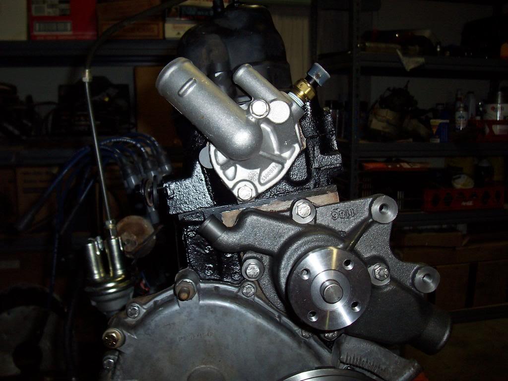
And 2 quick pics of the front of the engine with all the "bolt to the block" parts on. I still need to bolt the pulley to the crank and the pulley/fan onto the waterpump.

100_4748-1.jpg


100_4749-1.jpg
 
Last edited:
Anybody want to see some pics of the blasted/primed frame and body?
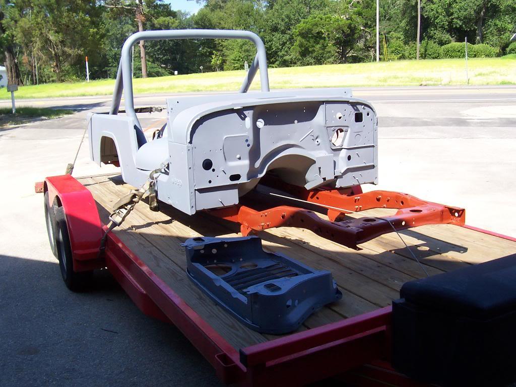
 
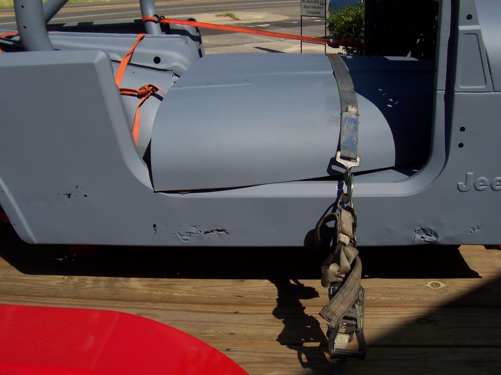
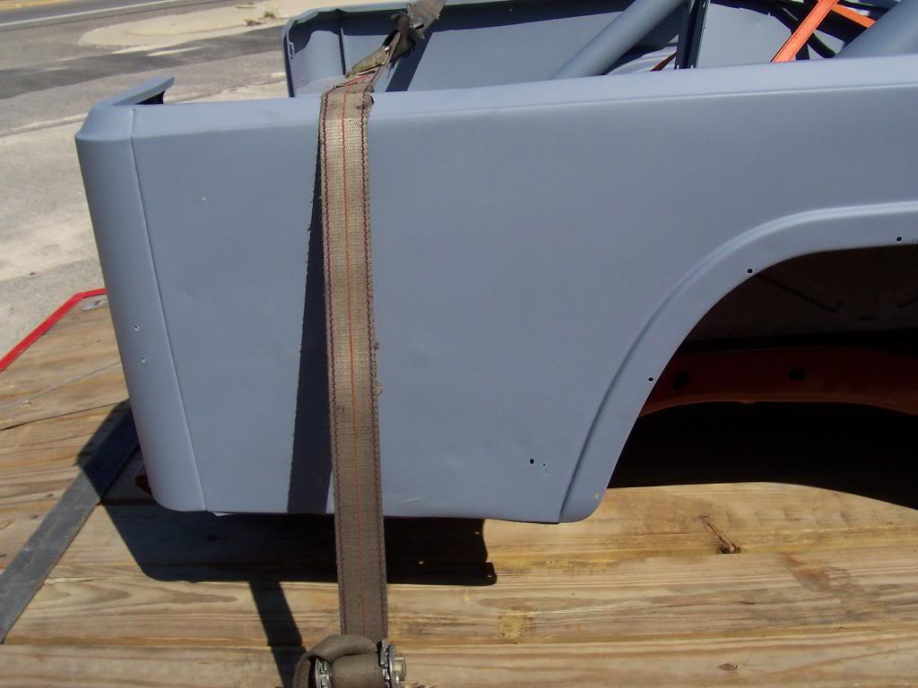
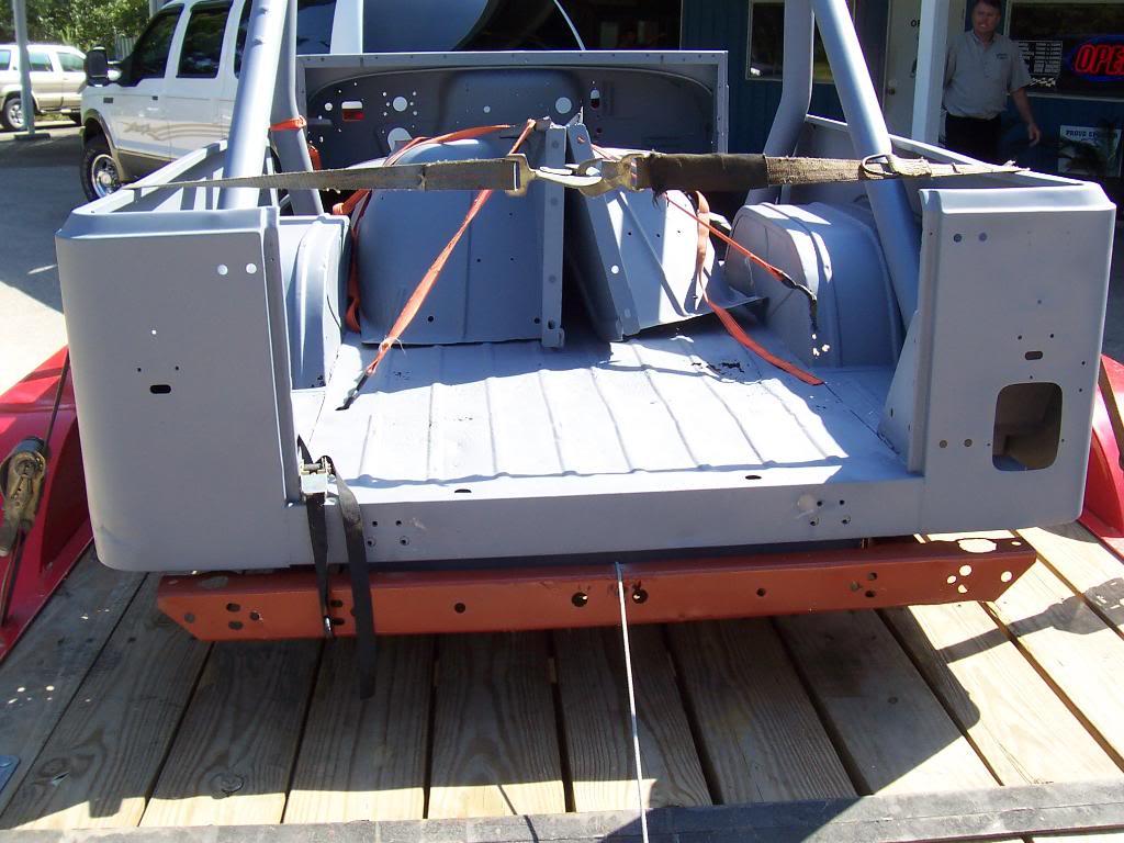
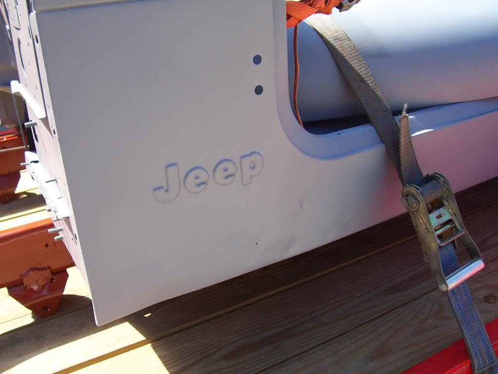
Went and saw my frame and body this morning. They just got back from blasting and epoxy priming. The frame just needs the rear crossmember welded back on and 3 body mout outriggers repaired. The frame stuff I already knew about so all the parts are already at the shop to make the necessary repairs. It might be ready by next week, maybe. The body looks about the same, didnt find any rust that I wasnt already aware of. Probably about 6 weeks till I get the body back.

Pics

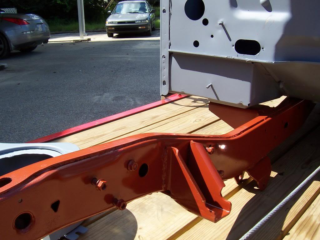
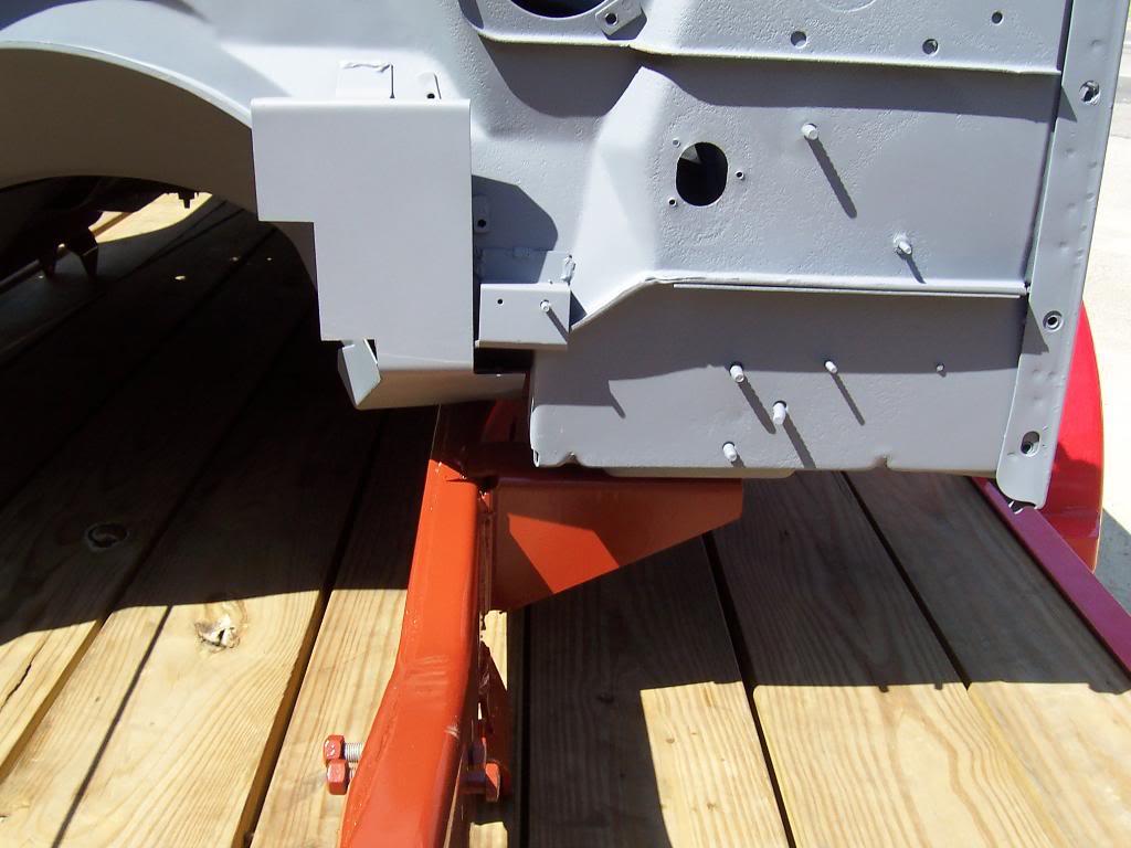
Quick overview shot. The frame is colored orangish red due to the type of epoxy primer that was used. This primer is supposed to be pretty good. They put this type of primer on the frame since there are only a few minor, localized areas of the frame that need to be ground back down, welded, etc. The body is a grey colored epoxy primer used more for bodywork. It isnt as good as the other stuff, but since so much welding/grinding/cutting needs to be done, this type of primer was used. Once all the new floors are welded in, another coat of primer/seam sealer will be put down. The most important thing about blasting is priming immediately after blasting to seal back the metal. It sounds kinda counter intuitive to blast first then do the repairs then reprime, but I wanted to make sure there was no hidden rust before we started repairing the metal work.

100_4750-1.jpg


Passenger side rocker panel, damage is evident.

100_4751-1.jpg


Passenger side rear quarter panel. Note just the one small hole.

100_4752-1.jpg


Rear shot. No real damage, minor dents on the driver side lower corner edge.

100_4753-1.jpg


Driver side front. No rust, but slight dents and damage were they usually rust at.

100_4754-1.jpg


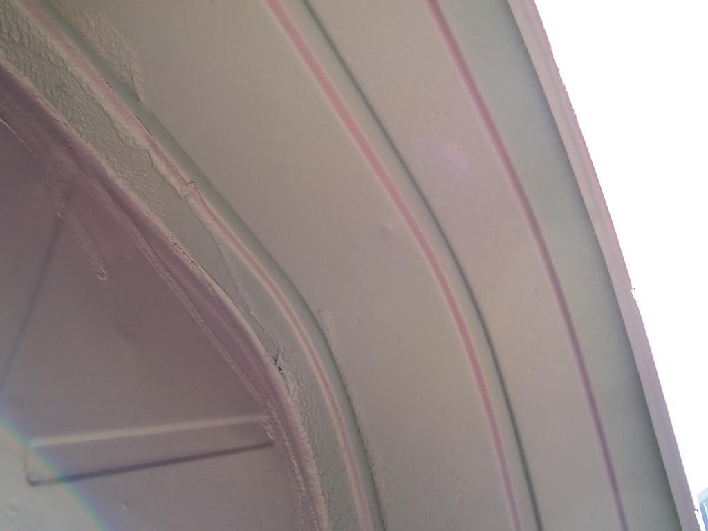
Driver side inner rear fender. Already knew about these rust holes.

100_4755-1.jpg


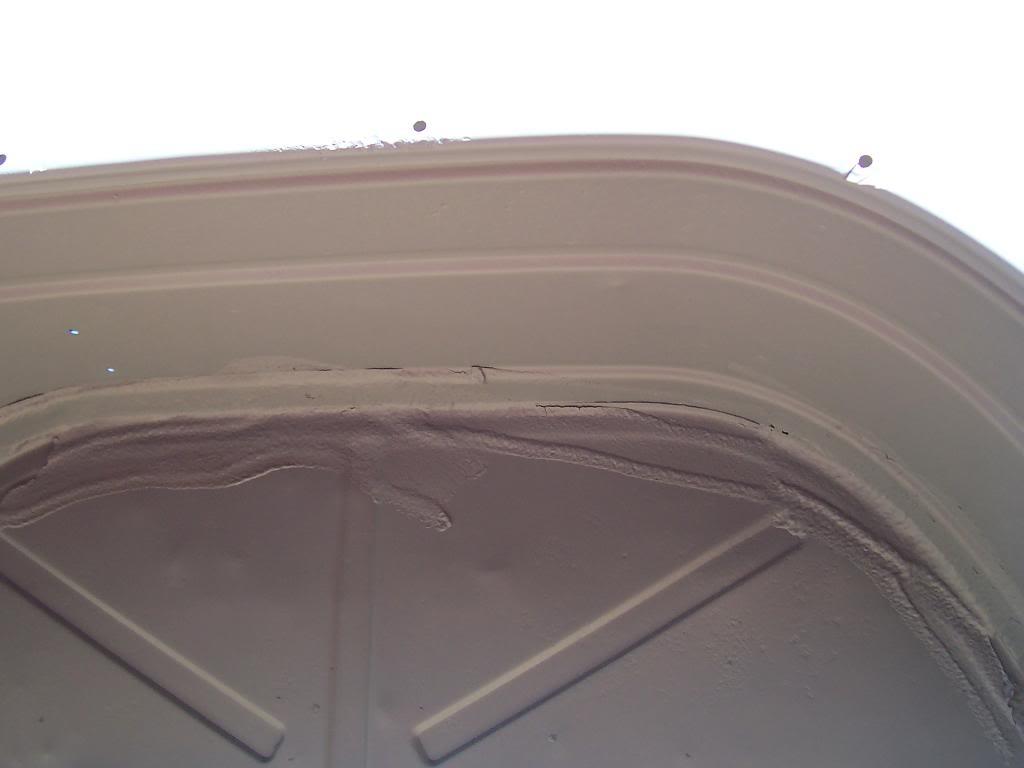
Passenger side inner rear fender. No rust, but you can see the original seam sealant that is stuck on permanently!

100_4756-1.jpg


Driver side rear quarter panel, one small hole.

100_4757-1.jpg


Rear overview

100_4758-1.jpg


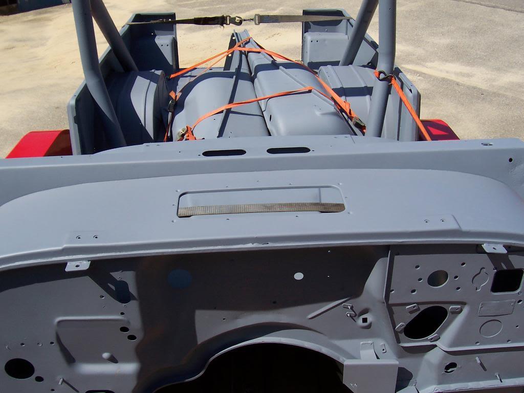
Front cowl/firewall, no damage

100_4759-1.jpg
 
Pic of hood and fenders. Slight dents on the front corners of fenders.

100_4760-1.jpg


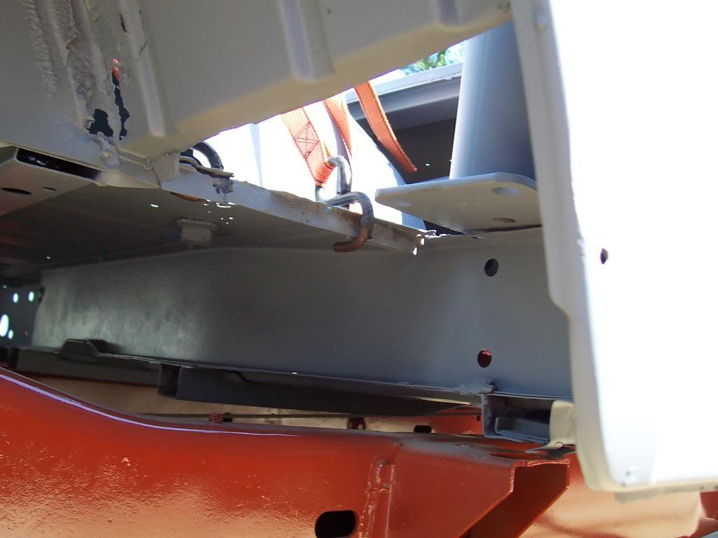
Closeup of driver side and passenger side lower firewall and frame rails. No damage.

100_4761-1.jpg


100_4762-1.jpg


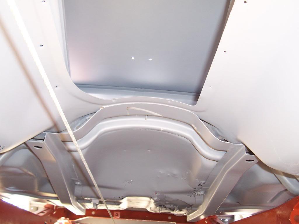
Under shot view, transmission tunnel. You can see daylight throught the damaged driver side floorboard, part behind seat, to the right of trans tunnel.

100_4763-1.jpg


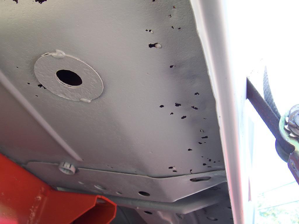
Driver side floor, outer edge. Bunches of small holes.

100_4764-1.jpg


Driver side, cubby hole area behind tail light, all good.

100_4765-1.jpg


Passenger side, cubby hole area behind tail light, note old asphalt stuck to metal, looks like bumps.

100_4766-1.jpg


Passenger side inner rear fender well, no damage.

100_4767-1.jpg


Pic of underbody floor riser, looks good.

100_4768-1.jpg
 
Back
Top