

You are using an out of date browser. It may not display this or other websites correctly.
You should upgrade or use an alternative browser.
You should upgrade or use an alternative browser.
Spankrjs' 1984 Long Term Project
- Thread starter spankrjs
- Start date


- City
- Biloxi
- State
- MS
- City
- Biloxi
- State
- MS
I have been working on wiring, not the most visually stimulating of jobs, but it needs to be done.
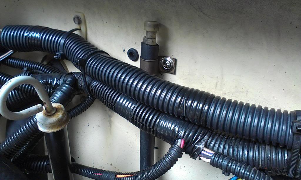
Since I corrected my "will not shut off with key problem", I was able to finish cleaning up most of the firewall mounted under hood wiring.
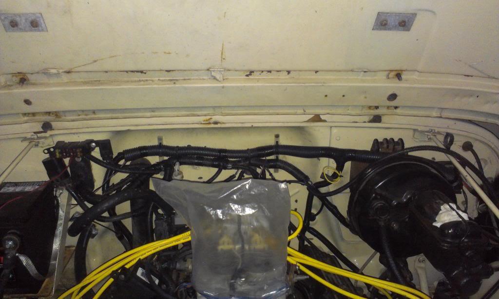
There is only so much clean up that can be accomplished on the back/top of the motor, these TBI engines just have too much stuff haphazardly strewn about the top of the engine to easily make it look "good".
And I finished my "from computer/dash gauges to transmission harness". It runs from the behind the glove box mounted TBI computer, behind the now installed defrost duct, over the steering column, and then through the firewall, using the old clutch linkage boot, worked out pretty sweet IMO.
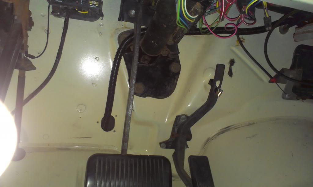
The above harness ties into some of the original Scrambler chassis wiring, and makes up one "transmission harness", that is, besides the TCC harness, which I left separate. The other harness, not the TBI TCC harness, contains the following:
1) Two wires for the factory transmission mounted reverse light switch (will wire up later)
2) The Dana 300 4wd ligh wire
3) The transmission temperature gauge sending unit wire
4) Three wires for the VSS - power, ground, signal
For now, it is all bundled up, need to terminate all the ends still:
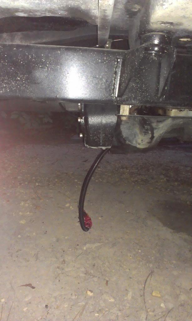
I was feeling pretty good about the wiring, until I checked the "Turbo City TBI harness to TCC harness". I was checking the wire that is supposed to have 12 volts, the one I need to splice through the brake light switch, no 12 volts.
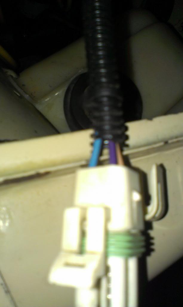
But, the "4th Gear Wire" did have 12 volts running through it, and it is not supposed to. I am hoping that Turbo City simply reversed these two wires at the computer. The correct colored wires are in the correct slots in the above pictured plug, so if they just put the wrong colored wires going to this plug, I will swap the wires at the computer end, I hope.
Besides the above mentioned wiring, still need to:
bolt in seats
make a coil bracket
install the license plate
install the air cleaner
Then go driving!!
That's it for now
Since I corrected my "will not shut off with key problem", I was able to finish cleaning up most of the firewall mounted under hood wiring.
There is only so much clean up that can be accomplished on the back/top of the motor, these TBI engines just have too much stuff haphazardly strewn about the top of the engine to easily make it look "good".
And I finished my "from computer/dash gauges to transmission harness". It runs from the behind the glove box mounted TBI computer, behind the now installed defrost duct, over the steering column, and then through the firewall, using the old clutch linkage boot, worked out pretty sweet IMO.
The above harness ties into some of the original Scrambler chassis wiring, and makes up one "transmission harness", that is, besides the TCC harness, which I left separate. The other harness, not the TBI TCC harness, contains the following:
1) Two wires for the factory transmission mounted reverse light switch (will wire up later)
2) The Dana 300 4wd ligh wire
3) The transmission temperature gauge sending unit wire
4) Three wires for the VSS - power, ground, signal
For now, it is all bundled up, need to terminate all the ends still:
I was feeling pretty good about the wiring, until I checked the "Turbo City TBI harness to TCC harness". I was checking the wire that is supposed to have 12 volts, the one I need to splice through the brake light switch, no 12 volts.
But, the "4th Gear Wire" did have 12 volts running through it, and it is not supposed to. I am hoping that Turbo City simply reversed these two wires at the computer. The correct colored wires are in the correct slots in the above pictured plug, so if they just put the wrong colored wires going to this plug, I will swap the wires at the computer end, I hope.
Besides the above mentioned wiring, still need to:
bolt in seats
make a coil bracket
install the license plate
install the air cleaner
Then go driving!!
That's it for now
- City
- Biloxi
- State
- MS
It not drivable yet, but almost. I underestimated the amount of time all these final odds and ends would take.
First project completed, my transmission/center of vehicle harness.
It drops down the firewall.

Runs on top of the transmission. It is secured with a cable tie to the lug on top of the transmission, and to the TV cable. Note the stock auto trans vent, more on that later. The tan wire is for the auto trans temp sender unit.
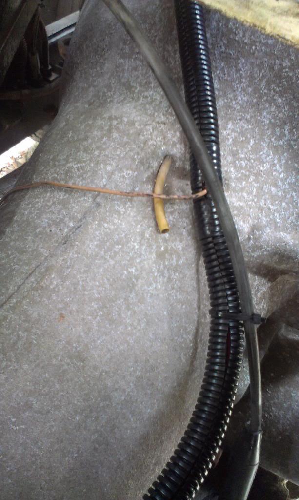
The harness then continues rearward. The orange wire is for the not hooked up yet 4WD indicator light, the red and white wires are the stock CJ reverse light wires.

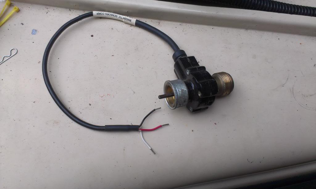
Quick picture of the aftermarket Vehicle Speed Sensor (VSS)
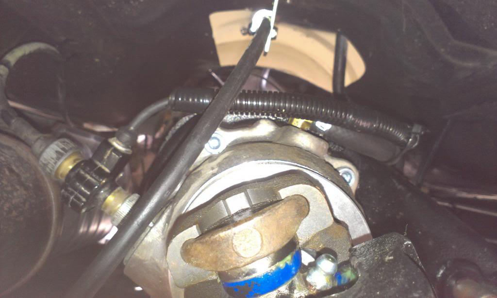
And installed, upper right hand corner of the picture.

And the VSS/speedometer cable installed. It is kind of close to the exhaust, but it clears. Since I need to cut off the cat, I might just redo the exhaust, too.
Quick picture of the mostly complete project, the harness ran, and the vent line(s) run.
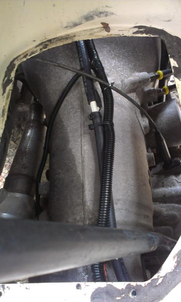
I did not like the stock auto trans vent, so I tied it into the Dana 300 vent hose with a vacuum "T". I am not worried about the Dana 300 puking oil up the vent hose into the auto trans, I don't think you can overfill it that much LOL. And, if some ATF ends up in the Dana 300, it wont hurt anything. I did not like that stock, open vent tube, very crappy IMO.

And the vent hose secured to the firewall in the stock location.
Once I install the correct Lokar shifter parts, and hook up the 4wd light wire/reverse lights, this will be 100% complete. I am still not sure how I am going to hook up the reverse lights. I will not be running the "neutral safety switch", so I think I can use this part of the shifter for the reverse lights, maybe.
First project completed, my transmission/center of vehicle harness.
It drops down the firewall.
Runs on top of the transmission. It is secured with a cable tie to the lug on top of the transmission, and to the TV cable. Note the stock auto trans vent, more on that later. The tan wire is for the auto trans temp sender unit.
The harness then continues rearward. The orange wire is for the not hooked up yet 4WD indicator light, the red and white wires are the stock CJ reverse light wires.
Quick picture of the aftermarket Vehicle Speed Sensor (VSS)
And installed, upper right hand corner of the picture.
And the VSS/speedometer cable installed. It is kind of close to the exhaust, but it clears. Since I need to cut off the cat, I might just redo the exhaust, too.
Quick picture of the mostly complete project, the harness ran, and the vent line(s) run.
I did not like the stock auto trans vent, so I tied it into the Dana 300 vent hose with a vacuum "T". I am not worried about the Dana 300 puking oil up the vent hose into the auto trans, I don't think you can overfill it that much LOL. And, if some ATF ends up in the Dana 300, it wont hurt anything. I did not like that stock, open vent tube, very crappy IMO.
And the vent hose secured to the firewall in the stock location.
Once I install the correct Lokar shifter parts, and hook up the 4wd light wire/reverse lights, this will be 100% complete. I am still not sure how I am going to hook up the reverse lights. I will not be running the "neutral safety switch", so I think I can use this part of the shifter for the reverse lights, maybe.
- City
- Biloxi
- State
- MS
I installed the correct throttle cable retainer clip. I ordered this part from the local Chevy dealership, when I ordered the next pictured part.
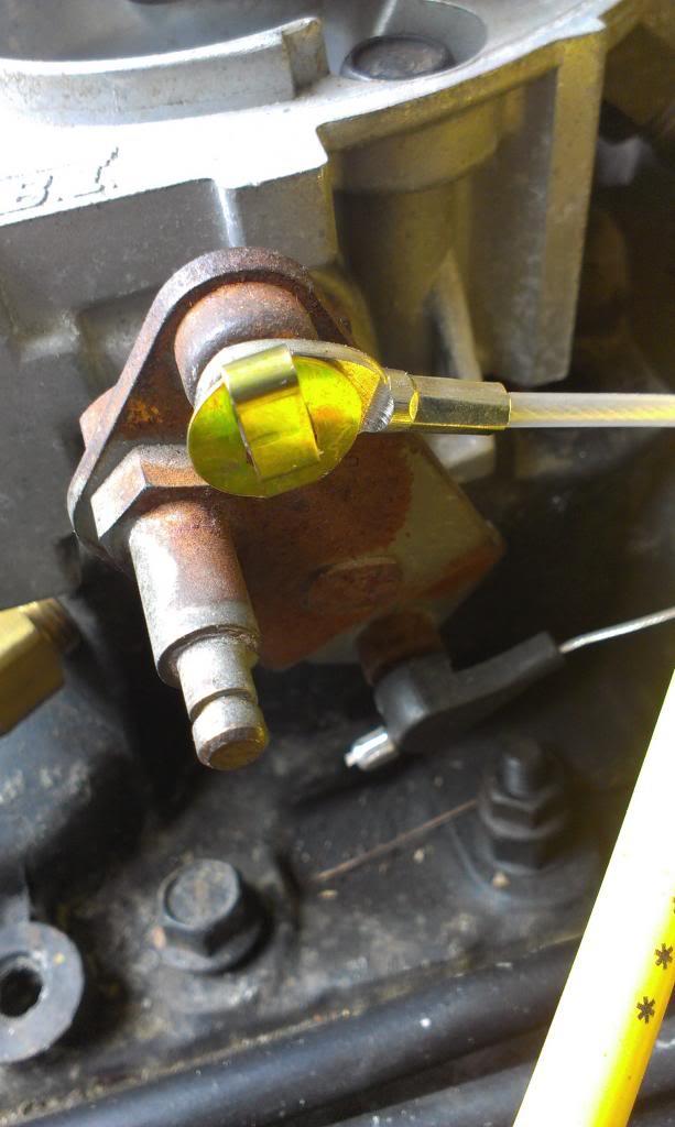
Picture of the Throttle Body. It was missing the spacer ring, so the stock air cleaner assembly could not be installed.
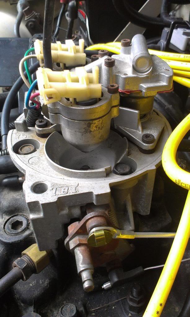
I ordered this part from GM, too. I could not find one in the junk yard. But, this part plus the throttle cable clip only cost $12, so no big deal.
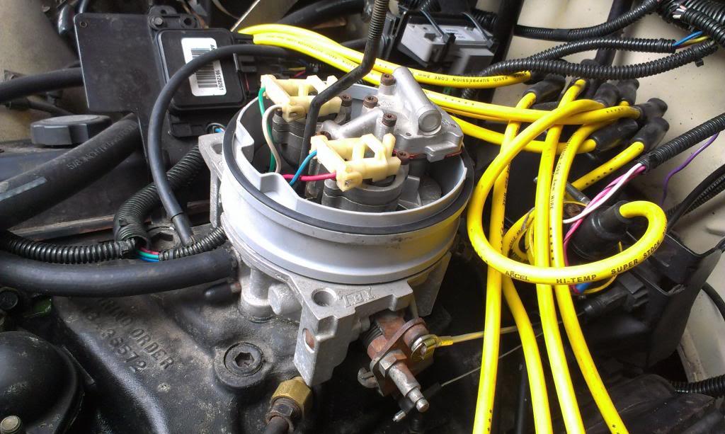
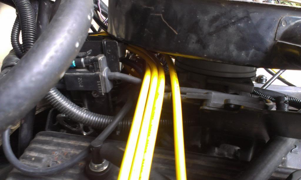
But, even with the stock spacer ring, the air cleaner would not clear the MAP sensor, which I could move, or the top of the distributor/spark plug wires, which I can not easily move.
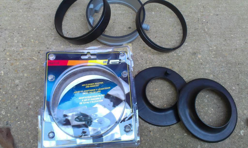
No big deal, I found this Mr. Gasket spacer/adapter set at the local Advance Auto Parts.
And, with the 1" spacer installed, the stock air cleaner clears everything perfectly.
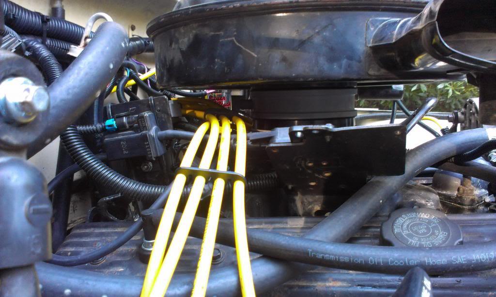
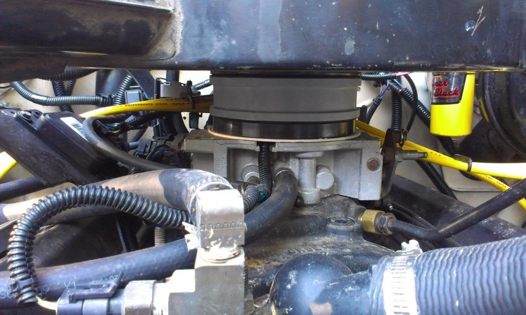
The spacer ring seals to the top of the TB with the white seal. The spacer ring has a slight ridge, which fits inside the stock spacer ring, and seals to the stock spacer rings seal. Everything fits nice and tight. I still need to pull the injector wiring seal from the junkyard harness. This will completely seal up the TB assembly. The stock threaded rod that secures the air cleaner assembly works, but is a tad short, but I can easily lengthen it, if I feel the urge to.
NOTE - the factory "thermal air trap door" still works on the air cleaner housing, too, so bonus.
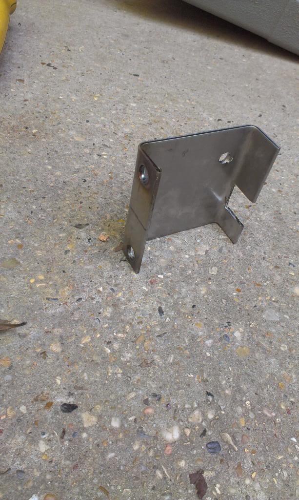
I also fabricated/installed a coil mounting bracket. I found this piece of metal at work, so decided to use it. Big mistake, it is stainless steel, so it was a PIA to drill and cut, but I made it work. It is more then beefy enough for this job.
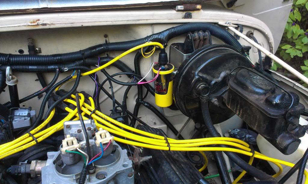
And installed. It is bolted to the firewall with two of the "brake master cylinder/booster to fire wall" bolts. It worked out pretty good. It is a bit fiddly to get to all the bolts, but it works. I might revisit this later on.
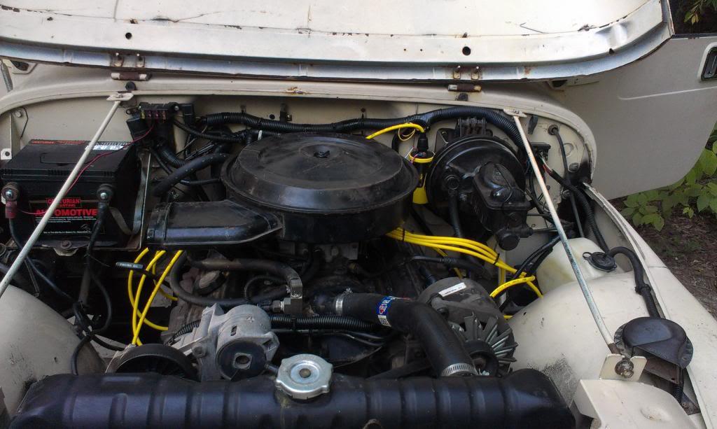
And a quick picture of the engine bay. Minus some PCV hose and replacing the EGR hose/fittings/stock coolant overflow tank, mostly done here.
Picture of the Throttle Body. It was missing the spacer ring, so the stock air cleaner assembly could not be installed.
I ordered this part from GM, too. I could not find one in the junk yard. But, this part plus the throttle cable clip only cost $12, so no big deal.
But, even with the stock spacer ring, the air cleaner would not clear the MAP sensor, which I could move, or the top of the distributor/spark plug wires, which I can not easily move.
No big deal, I found this Mr. Gasket spacer/adapter set at the local Advance Auto Parts.
And, with the 1" spacer installed, the stock air cleaner clears everything perfectly.
The spacer ring seals to the top of the TB with the white seal. The spacer ring has a slight ridge, which fits inside the stock spacer ring, and seals to the stock spacer rings seal. Everything fits nice and tight. I still need to pull the injector wiring seal from the junkyard harness. This will completely seal up the TB assembly. The stock threaded rod that secures the air cleaner assembly works, but is a tad short, but I can easily lengthen it, if I feel the urge to.
NOTE - the factory "thermal air trap door" still works on the air cleaner housing, too, so bonus.
I also fabricated/installed a coil mounting bracket. I found this piece of metal at work, so decided to use it. Big mistake, it is stainless steel, so it was a PIA to drill and cut, but I made it work. It is more then beefy enough for this job.
And installed. It is bolted to the firewall with two of the "brake master cylinder/booster to fire wall" bolts. It worked out pretty good. It is a bit fiddly to get to all the bolts, but it works. I might revisit this later on.
And a quick picture of the engine bay. Minus some PCV hose and replacing the EGR hose/fittings/stock coolant overflow tank, mostly done here.
- City
- Biloxi
- State
- MS
My next big task was figuring out the TCC wiring. I bought the tools pictured below from NAPA. They make weather pack connector disassembly a snap.

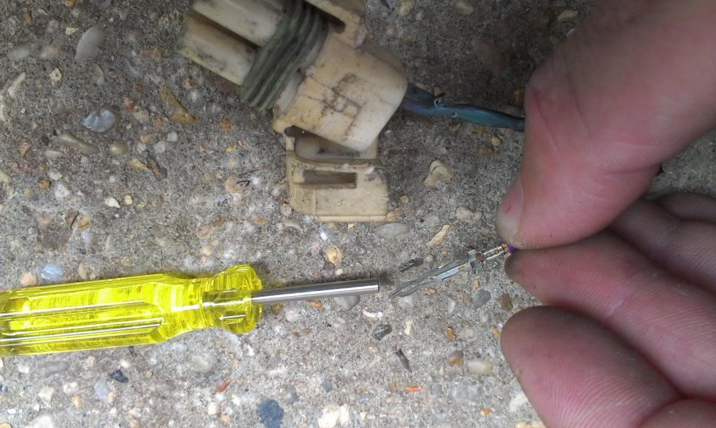
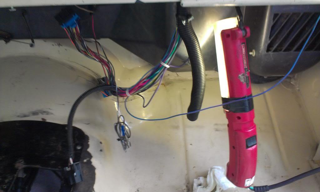
Well, turns out, I didn't need them. There was one loose wire in the TBI harness. Well, it turns out that this was the other end of the TCC harness, the wire that needs to be hooked up to 12 volt switched power.
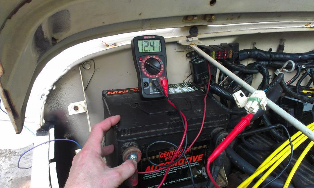
I hooked the end of the wire to the battery:
And what do you know, 12 volts!!!
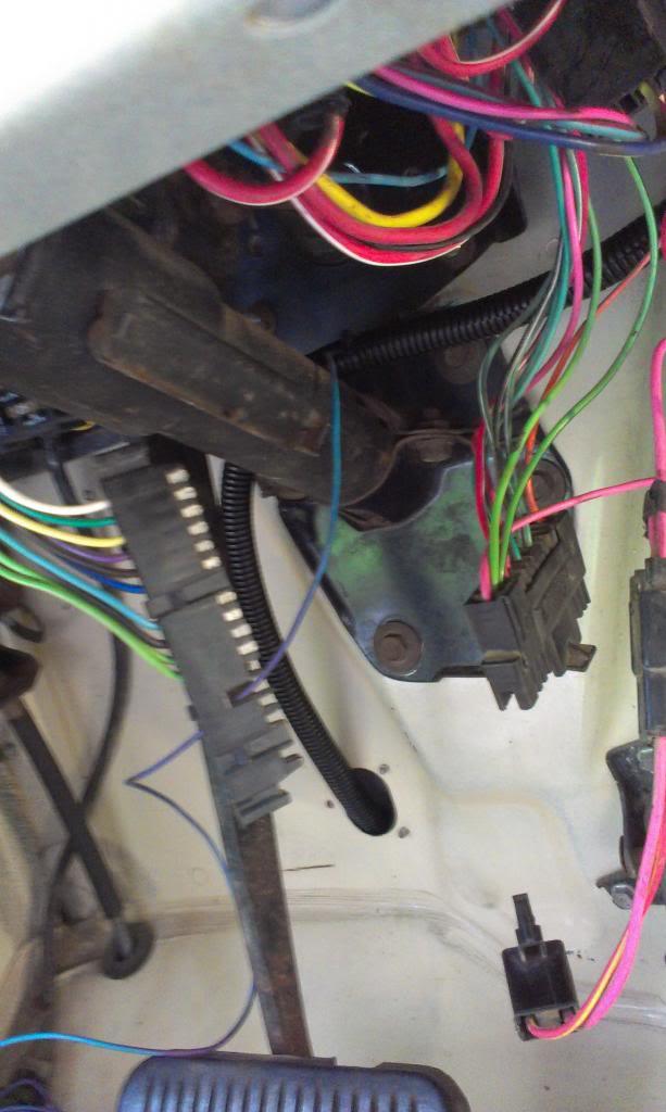
So, at least no long lengthy diagnostics required. I ran this newly discovered wire through my "behind the defrost duct hose", to the steering column.
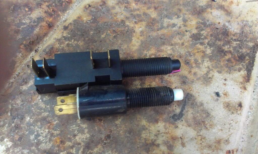
The trick with this wire: This wire locks up the torque convertor. You do not want a locked up convertor while braking. So, I wired it up through this nifty early 80's GM brake light switch. Note the two sets of terminals: One set is "normally closed" - i.e. brake lights, the other is "normally open" - used with factory cruise control.
Quick picture showing the stock brake light switch and my dual switch.
A quick redneck bench test, figured out which set of connectors does what.
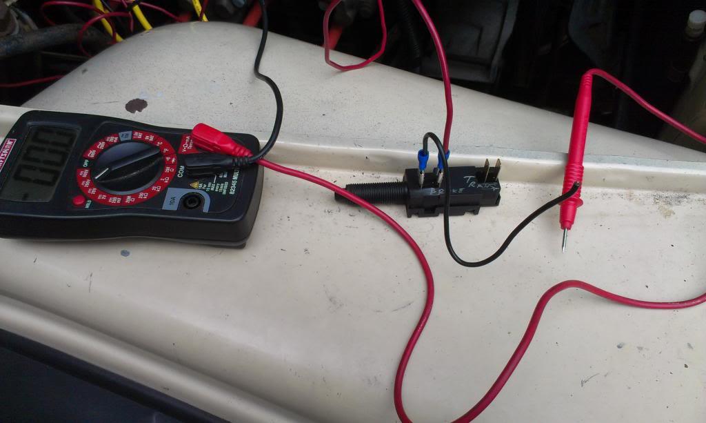
And ready to install. I did have to remove the factory, crappy, stamped metal brake light switch retainer thingy, pictured below. I secured the new switch with two 1/2" fine thread nuts. Works perfect, and super secure. This method of attachment also allows for very finite adjustment of the switch, which is crucial.

And installed. I turned the switches terminals toward the driver side. It fits perfect, and the factory brake light switch plugs back on like it was meant to. I might snag another stock plug, to replace my two female spade connectors. But for now, it works, and it is a big PIA to get to this thing!!!!!!!!!!!!!!!!!!!!!!!!!!!!!!!!!!!!!!!!
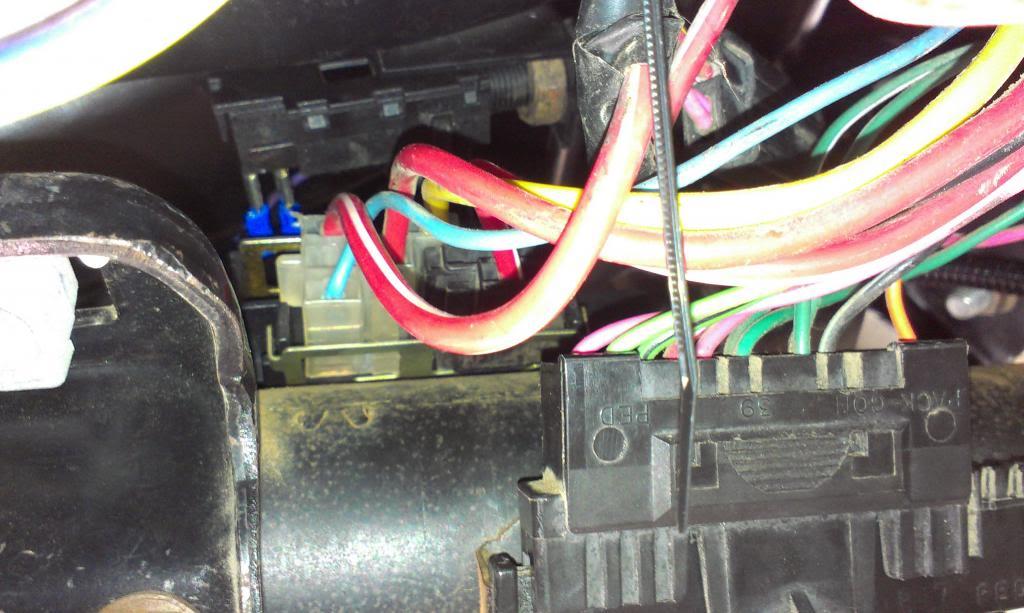
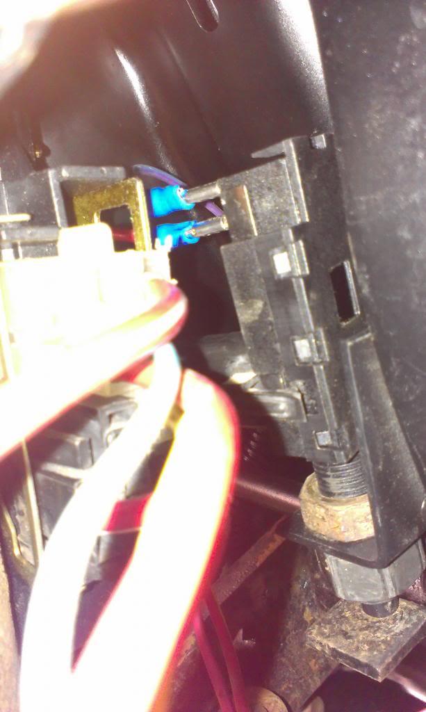
Well, turns out, I didn't need them. There was one loose wire in the TBI harness. Well, it turns out that this was the other end of the TCC harness, the wire that needs to be hooked up to 12 volt switched power.
I hooked the end of the wire to the battery:
And what do you know, 12 volts!!!
So, at least no long lengthy diagnostics required. I ran this newly discovered wire through my "behind the defrost duct hose", to the steering column.
The trick with this wire: This wire locks up the torque convertor. You do not want a locked up convertor while braking. So, I wired it up through this nifty early 80's GM brake light switch. Note the two sets of terminals: One set is "normally closed" - i.e. brake lights, the other is "normally open" - used with factory cruise control.
Quick picture showing the stock brake light switch and my dual switch.
A quick redneck bench test, figured out which set of connectors does what.
And ready to install. I did have to remove the factory, crappy, stamped metal brake light switch retainer thingy, pictured below. I secured the new switch with two 1/2" fine thread nuts. Works perfect, and super secure. This method of attachment also allows for very finite adjustment of the switch, which is crucial.
And installed. I turned the switches terminals toward the driver side. It fits perfect, and the factory brake light switch plugs back on like it was meant to. I might snag another stock plug, to replace my two female spade connectors. But for now, it works, and it is a big PIA to get to this thing!!!!!!!!!!!!!!!!!!!!!!!!!!!!!!!!!!!!!!!!
- City
- Biloxi
- State
- MS
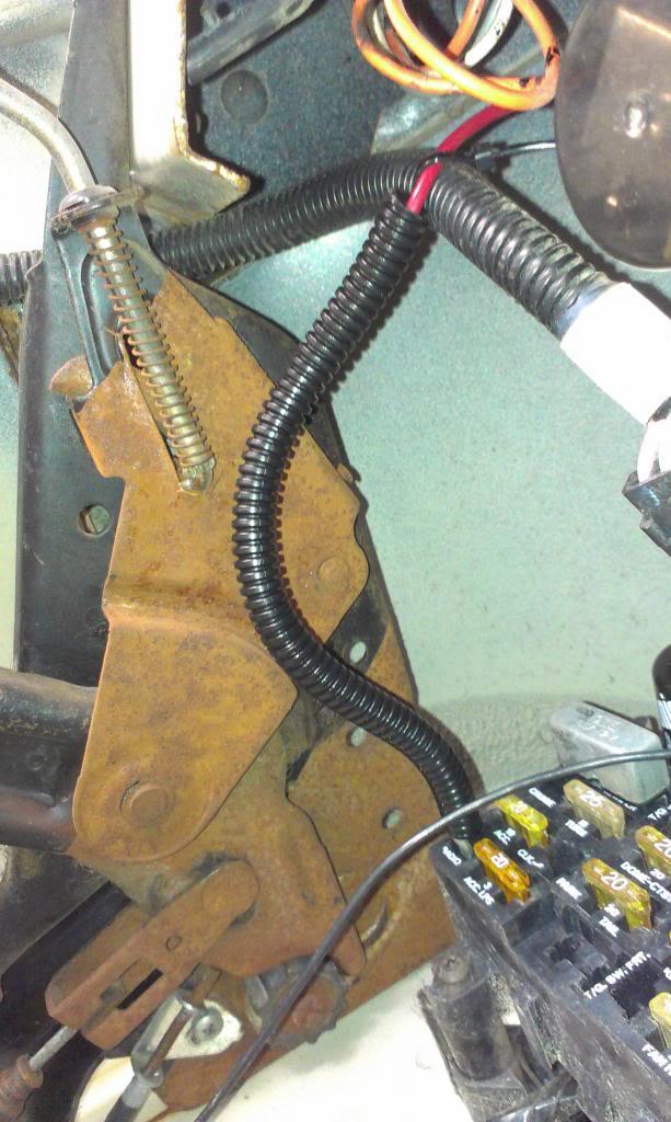
And one last picture of the brake light switch.
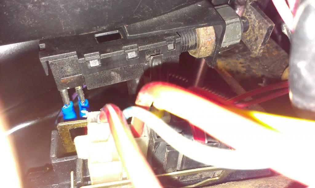
I used the factory "radio" power supply to power up this switch, so it is fuse protected.
I was glad to get that project complete!!!!!!!!!!!!
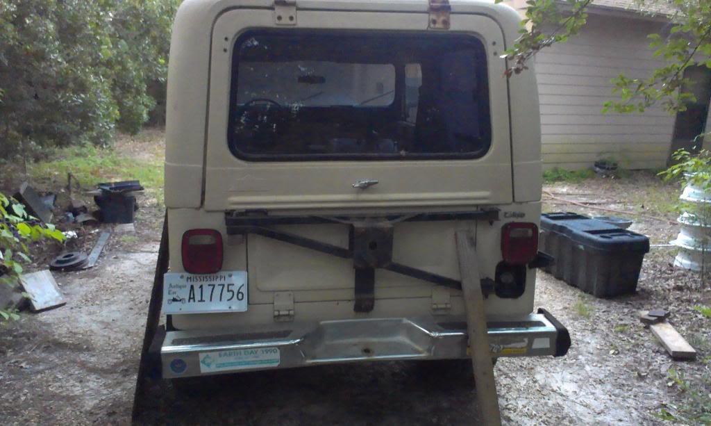
Installed my license plate/license plate bracket. Both brake lights work. All of my lights work except for the driver side running lights, so either a bulb/ground problem to solve.
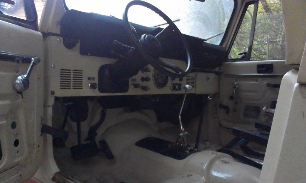
Quick picture of the interior, all the wiring is about finished. Still need to install seats/door panels/finish shifter modifications, plus I have a free Tuffy console to install, more on that later.
And a quick overall picture.
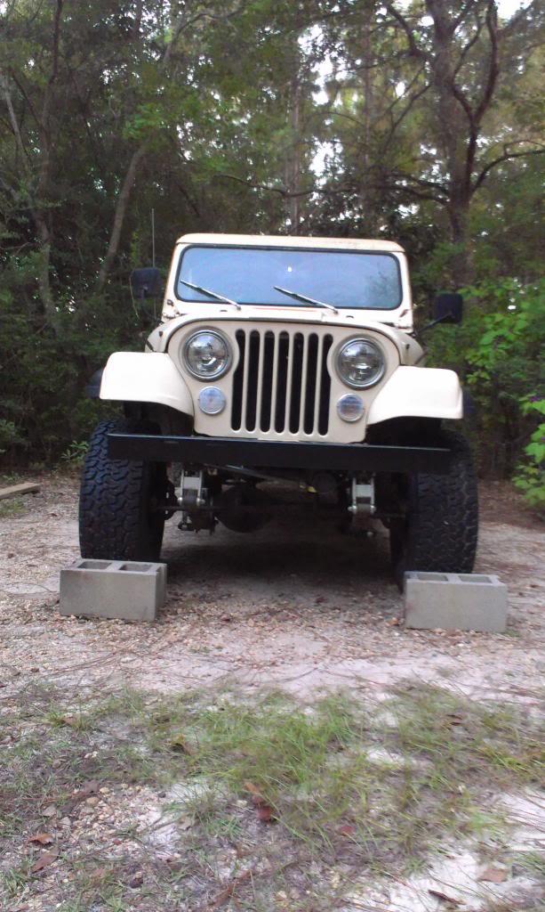
Getting close, that's it for now
I used the factory "radio" power supply to power up this switch, so it is fuse protected.
I was glad to get that project complete!!!!!!!!!!!!
Installed my license plate/license plate bracket. Both brake lights work. All of my lights work except for the driver side running lights, so either a bulb/ground problem to solve.
Quick picture of the interior, all the wiring is about finished. Still need to install seats/door panels/finish shifter modifications, plus I have a free Tuffy console to install, more on that later.
And a quick overall picture.
Getting close, that's it for now


- City
- Biloxi
- State
- MS
Looks great! Did you hire a contortionist to install that switch?
LOL
 Surprisingly, without the seats or center console in the way, it wasn't too bad to lay on the floor, head toward fthe firewall, on my back, and work with the switch. If the seats would have been installed, big PIA
Looking good
Appreciate it
Back at you


- City
- Biloxi
- State
- MS
I got the seats installed last night.
Picture of all the parts:

The factory seat sliders, and all the bolts, nuts, and spacers. Everything except for the "seat frame to body bolts", they were on the floor of the Jeep when this picture was taken. One thing to note - the seat slider to seat bracket attachment studs use 5/16 fine thread flange nuts, not the easiest thing to find.

The stock driver side and passenger side "flip forward" seat brackets:

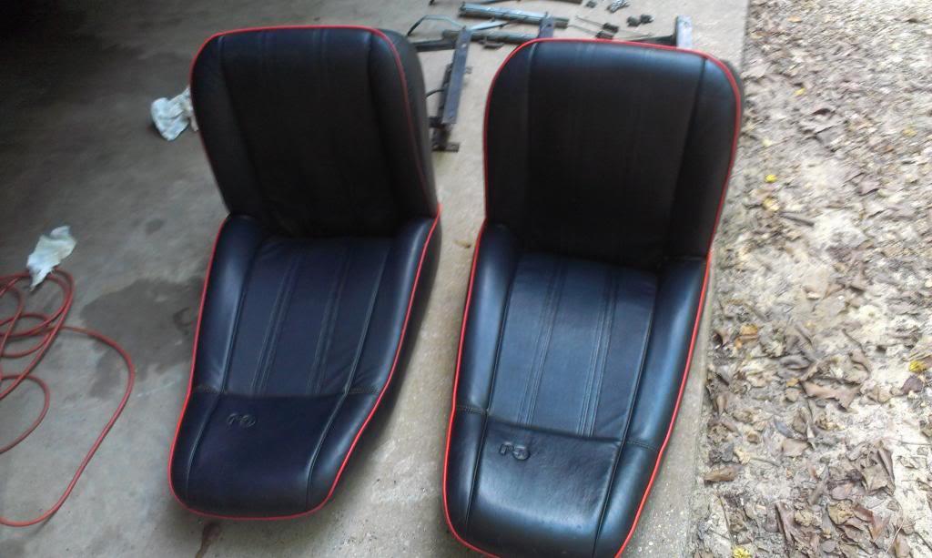
And the "Spring Special" seats I am using. The initial cleaning cleaned them up pretty good, they still need to be cleaned up a bit better. While they are not perfect, they are in great shape, and I love factory seats in a CJ.
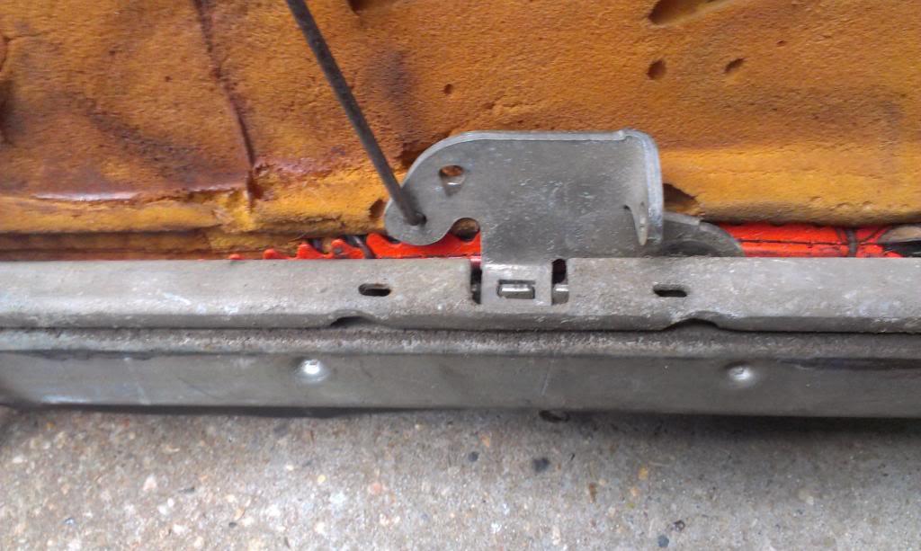
All of these stock parts bolted right up. Picture of how the little rod goes:

Close up, showing where the spacers go.

I am missing the little spring on the passenger side seat slider. I also need to clean up one of the seat slider to seat bracket studs, the threads are slightly boogered. But, both seats bolted together, and both slide forward and backward just fine.
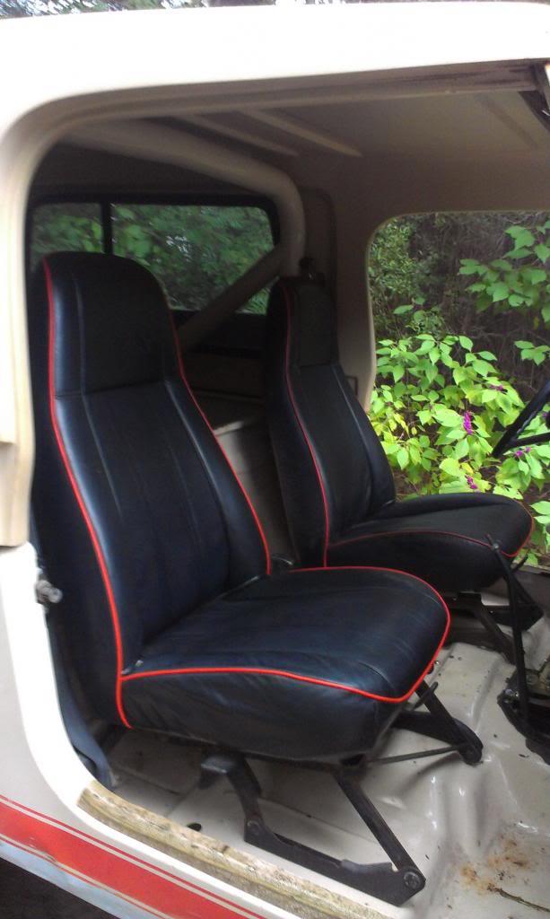
And installed. I think the orange piping adds a bit of "raciness" to the V8 powered Scrambler, looks pretty cool IMO. I still need to install the door panels, and finish the shifters/boots, but at least it is drivable now.


Picture of all the parts:
The factory seat sliders, and all the bolts, nuts, and spacers. Everything except for the "seat frame to body bolts", they were on the floor of the Jeep when this picture was taken. One thing to note - the seat slider to seat bracket attachment studs use 5/16 fine thread flange nuts, not the easiest thing to find.
The stock driver side and passenger side "flip forward" seat brackets:
And the "Spring Special" seats I am using. The initial cleaning cleaned them up pretty good, they still need to be cleaned up a bit better. While they are not perfect, they are in great shape, and I love factory seats in a CJ.
All of these stock parts bolted right up. Picture of how the little rod goes:
Close up, showing where the spacers go.
I am missing the little spring on the passenger side seat slider. I also need to clean up one of the seat slider to seat bracket studs, the threads are slightly boogered. But, both seats bolted together, and both slide forward and backward just fine.
And installed. I think the orange piping adds a bit of "raciness" to the V8 powered Scrambler, looks pretty cool IMO. I still need to install the door panels, and finish the shifters/boots, but at least it is drivable now.

- City
- Cobourg, Ontario, Cana
- State
- da
at least it is drivable now.
VIDEO!!! Where is the dam video!!!
- City
- Biloxi
- State
- MS
I also received the shifter parts I needed from Lokar, to convert the Turbo 350 shifter that I have to function properly with the 4L60/700R4 that I have. Basically, a new knob insert, the detent part of the base, and the correct selector shaft arm. I still need to install these parts, shouldn't be too bad.

Anyway, after bolting the seats in, I decided to take it for an initial drive
It drove great in the driveway, while in first gear. It also goes great in reverse. But, when it got out on the street, it didn't seem to shift right. It wanted to "hang" in first, and when it did shift, it was way too soft. I only drove it about 300 yards, turned around, and parked it
I don't know too much about automatics, but I do know they are not supposed to shift this "soft", it can burn stuff up.
I have two issues with the engine that could be causing this, even if they are not fully responsible:
1) Engine Timing - all the books ay to set the timing to 0 dgrees at TDC. This is how I have it set. But, the Turbo City TBI instructions say to set it at 6 degrees BTDC. The engine currently seems a bit "off" while accelerating, it cant hurt to adjust the timing, pretty simple thing to do.
2) It stinks. The more I run the engine, the more it stinks. I am not sure if it is still the Cat burning up, or something is stuck in the muffler, i.e. a rats nest. I just know it stinks, maybe it is plugging up the exhaust?? But, the engine idles fine, so probably not.
I am also going to revisit the Throttle Valve (TV) cable, that runs from the Throttle Body to the transmission. This cable is responsible for a majority of the transmissions functions - internal line pressure, shift points, etc. If it is not adjusted correctly, or damaged, it can cause issues.
When I checked the transmission fluid the other day, after finally being able to shift into drive, it was a quart low. So, maybe after actually moving it a bit, the fluid is low. Easy enough to check.
One thing I noticed: it works perfect in reverse. It feels really strong and connected, like it should. In forward gears, it doesn't seem to be "grabbing" as good, if that makes sense. It is not slipping, but it doesn't feel like a "solid fluid coupling", either, somewhere in between.
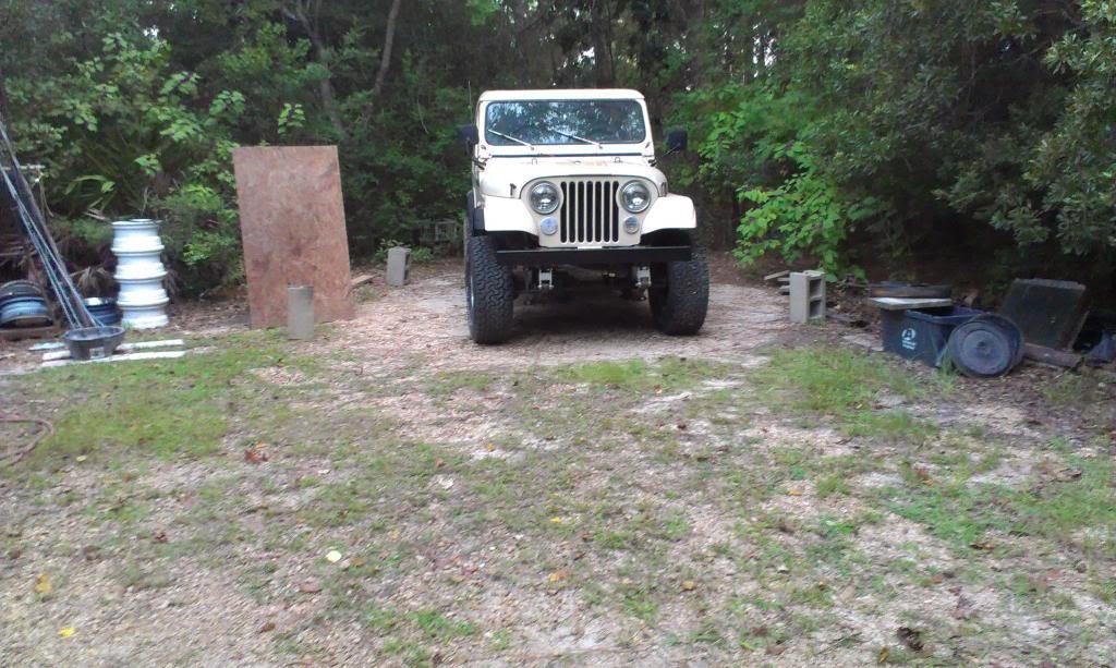
Quick picture, showing that it did move, kind of:
Hopefully, I can get this figured out fairly easily/cheaply. The Scrambler did steer good, the suspension wasn't too stiff, and the brakes are OK, still need to bleed them one more time.
That's it for now
Anyway, after bolting the seats in, I decided to take it for an initial drive
It drove great in the driveway, while in first gear. It also goes great in reverse. But, when it got out on the street, it didn't seem to shift right. It wanted to "hang" in first, and when it did shift, it was way too soft. I only drove it about 300 yards, turned around, and parked it
I don't know too much about automatics, but I do know they are not supposed to shift this "soft", it can burn stuff up.
I have two issues with the engine that could be causing this, even if they are not fully responsible:
1) Engine Timing - all the books ay to set the timing to 0 dgrees at TDC. This is how I have it set. But, the Turbo City TBI instructions say to set it at 6 degrees BTDC. The engine currently seems a bit "off" while accelerating, it cant hurt to adjust the timing, pretty simple thing to do.
2) It stinks. The more I run the engine, the more it stinks. I am not sure if it is still the Cat burning up, or something is stuck in the muffler, i.e. a rats nest. I just know it stinks, maybe it is plugging up the exhaust?? But, the engine idles fine, so probably not.
I am also going to revisit the Throttle Valve (TV) cable, that runs from the Throttle Body to the transmission. This cable is responsible for a majority of the transmissions functions - internal line pressure, shift points, etc. If it is not adjusted correctly, or damaged, it can cause issues.
When I checked the transmission fluid the other day, after finally being able to shift into drive, it was a quart low. So, maybe after actually moving it a bit, the fluid is low. Easy enough to check.
One thing I noticed: it works perfect in reverse. It feels really strong and connected, like it should. In forward gears, it doesn't seem to be "grabbing" as good, if that makes sense. It is not slipping, but it doesn't feel like a "solid fluid coupling", either, somewhere in between.
Quick picture, showing that it did move, kind of:
Hopefully, I can get this figured out fairly easily/cheaply. The Scrambler did steer good, the suspension wasn't too stiff, and the brakes are OK, still need to bleed them one more time.
That's it for now
- City
- Biloxi
- State
- MS

- City
- God's Country
- State
- AR
The factory seat sliders, and all the bolts, nuts, and spacers. Everything except for the "seat frame to body bolts", they were on the floor of the Jeep when this picture was taken. One thing to note - the seat slider to seat bracket attachment studs use 5/16 fine thread flange nuts, not the easiest thing to find.
Question, didn't you have to drill one of the mounting holes for that slider in your passenger seat mount? I had to on both of my CJ-7's.....
Second, totallystainless should have those bolts if anyone needs them. They look similar to the bolts holding the center caps on the OEM wagon wheels.
http://www.jeepforum.com/forum/f8/refurbishment-factory-cj-wheels-1357559/index2.html#post13429335
Attachments

- City
- Redmond
- State
- OR
TV cable adjustment on the 700R4 is critical to proper operation. And having the right cable is critical to proper adjustment. On my Waggy conversion I tried making a S-10 cable work on a V8- couldn't get it right. I finally ordered a cable for a truck (that's what the intake/throttle body/linkage were off of.) Got it adjusted and the difference in feel was amazing.
Here's a copy of an article...
T.V. Cable Adjustment
WARNING: PERMANENT DAMAGE WILL OCCUR IF THE T.V. CABLE IS NOT ADJUSTED OR HOOKED UP.
THE DAMAGE WILL OCCUR WITHIN A FEW FEET OF DRIVING THE VEHICLE!
The TV cable on the 700R4 and 200-4R transmissions controls line pressure, shift points, shift feel, part throttle downshifts, and detent (full throttle) downshifts. So if the TV cable is not adjusted properly, it can cause numerous transmission problems.
The TV cable is connected to and operates the throttle lever, and bracket assembly mounted on the valve body. The function of the throttle lever and bracket assembly I to transfer the movements of the throttle plate in the carburetor to the TV plunger in the valve body. This causes TV pressure and line pressure to increase according to throttle opening and also controls modulated and detent downshifts. The proper adjustment of the TV cable is based on the TV plunger being fully depressed with the engine at wide-open throttle (see figure 9). When the TV cable is properly adjusted the movement of the TV plunger in the valve body is calibrated to the movement of the fuel delivery system. This means the transmission will always have the correct oil pressure and shift feel regardless of engine torque. Simply put, due to this calibration, engine torque and transmission line pressure/shift feel will always be in balance.
If a change is made, such as a different carburetor installed, the change in geometry could disrupt this balance and proper adjustment may never be achieved.
Many people try to defeat the self-adjusting TV cable and tailor shift points of shift feel. However, remember that on the 700R4 and 2004R Transmission the TV cable controls both shift feel (clutch apply pressure) and shift points, you therefore cannot alter one without altering the other.
Let's discuss briefly what happens when someone tailors the TV cable:
Shortening the Cable : If you shorten the cable (move it towards the adjuster tab), this raises both one pressure and shift point. However, when the drive performs a full throttle downshift the TV cable will readjust to its approximate normal position.
Lengthening the Cable : If you lengthen the valve, this lowers both line pressure and shift points. Under this condition, the TV cable will not readjust during a full throttle downshift. What you have effectively done is allowed the engine torque to be ahead of transmission line pressure and shift points. Operating the vehicle under this condition will cause premature clutch wear and transmission malfunction.
DIAGNOSIS
A TV cable that is sticky; misadjusted, broken or incorrect for the vehicle can cause various transmission malfunctions. A sticky or binding TV cable can result in delayed or full throttle upshifts (figure 9). At other times, the TV cable may stick or bind only when the engine off. To check for this problem, run the engine at idle with the transmission selector in neutral and the parking brake set. Pull the end of the TV cable located on the throttle linkage, through its full range of travel, then release it. It should return to rest against the cable terminal (figure 10), it may be caused by one or more of the following conditions:
1. A sharply bent or damaged TV cable hosing. To correct this problem, try rerouting the cable. If this doesn't cure the problem, replace the cable.
2. A burr or sharp end on the TV link. This condition would cause the link to drag in the TV cable housing. You can correct this situation by filing the end smooth but Do Not shorten the link.
3. Misalignment of the throttle lever and bracket assembly on the valve body. Correct the alignment and torque the bolts to the proper specifications as noted in your service manual.
4. A bent TV link. Straighten or replace the link as required.
5. A binding or damaged throttle lever and bracket assembly. Straighten or replace the assembly as required.
6. An unhooked or damaged throttle lever spring. Reconnect the spring if it is unhooked. If it is damaged, replace the throttle lever and bracket assembly.
7. An incorrectly adjusted TV cable. (A) If the cable is adjusted too long, one of the following conditions may result: (1) early shifts, slipping, and/or no detent downshifts; (2) low line pressure. (B) If the cable is adjusted shore, or not hooked up at all, line pressure and shift points will rise and full throttle operation may not be possible.
ADJUSTMENTS
Before adjusting the TV cable, check the following:
1. Transmission oil level. Correct if necessary.
2. Proper engine operation. This can cause problems similar to a malfunctioning transmission.
3. Dragging brakes. This can cause detract from vehicle performance and cause transmission malfunction.
4. Check the TV cable to insure that it is the right part for the vehicle. If you do not hear at least one "click" from the TV cable during the adjustment procedure, it may be the wrong part.
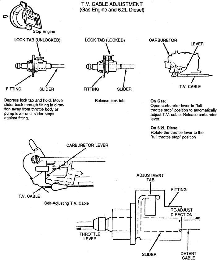
5. Check the cable to insure that it is properly connected at the transmission. "Clicks" will still be heard during adjustment.Adjustment procedure (self-adjusting cable)1. Stop the engine.
Adjustment procedure (self-adjusting cable)
1. Stop the engine.
2. Depress the adjusting tab and move the slider back through the fitting away from the carburetor until it stops.
3. Release the adjustment tab.
4. Move the throttle linkage to rest against the full throttle stop, then release it .
5. Check the cable to insure that it is not sticking or binding.
6. Road test the vehicle.
7. If the problem still exists, refer to the cable diagnosis section.
SEE DIAGRAM
TV CABLE BRACKET FABRICATION
This section is only for those that do not have a previous TV cable setup, or for those who's TV cable will not fit into the specifications in the previous pages.
Proper installation and adjustment of the TV cable is the most important aspect of a transmission. Don't think of it as "just a kick-down cable" - on the nonvacuum-modulated Th700R4 and Th2004R the TV cable controls line pressure, shift points, shift feel, part-throttle downshifts, and detent downshifts! As the accelerator pedal is depressed and the throttle opens, the TV linkage relays the motion to the valve body's throttle plunger. In stock installations, the geometric relationship between the TV cable and carb throttle shaft bellcrank produces the required TV cable extension (pull) for the transmission to function properly under different degrees of throttle opening. Failure to preserve the correct geometric relationship in custom installations will inevitably lead to early transmission failure.
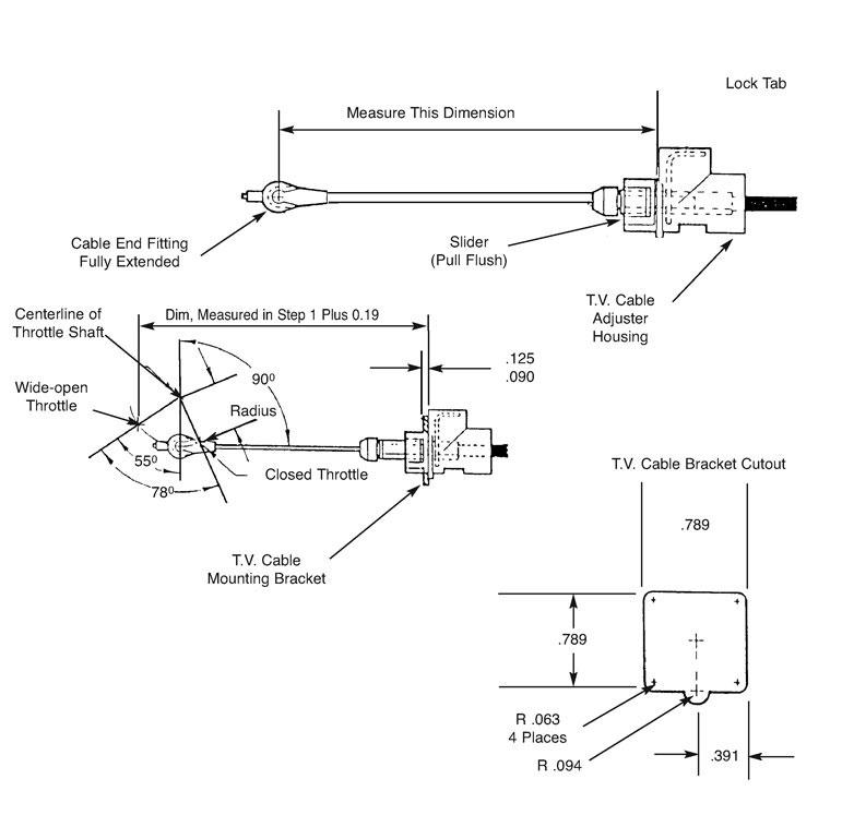
1. Measure your TV cable to establish its particular mounting dimension as follows: First retract the slider by depressing the lock tab, then pull the cable housing until the flats on the slider are flush with the end of the adjuster housing. (To illustrate components in this photo the slider is shown extended, and the lock tab is not fully inserted through the bracket face.)
2. Then, with the slider retracted, fully extend the cable by pulling the cable end fitting out until it stops. Holding the end fitting out, measure the dimension from the face on the adjuster housing that registers with the mounting bracket to the center of the cable and connector.
3. Add 1/16 inch (.19) to the measurement obtained in step 2 - this is the perpendicular measurement from the rear face of the TV cable mounting bracket to the wide-open-throttle position of the TV cable connector pin on the throttle bellcrank.
4. To ensure that the TV mechanism moves in correct proportion to the throttle opening, the TV cable bellcrank must be perpendicular (90 degrees) to the TV cable when the throttle is about a quarter open. The cable connector pin's mounting location must be established on the throttle bellcrank at a radius of 1.094 to 1,125 inches (also see step 3). If there is no suitable existing hole in the bellcrank, drill a new hole or fabricate a suitable attachment, as required, to properly locate the connector pin.
5. The proper location of the TV cable mounting bracket is determined by the angular and radial position of the TV cable connector pin on the throttle bellcrank. Make sure that other cables and rods will not interfere with the TV cable. Mount the TV cable adjuster housing so that the lock tab is readily accessible.
6. Fabricate the bracket using .090- to .125-inch sheet metal to these housing cutout dimensions. If thicker stock is used, a chamfer is required on two sides of the cable mounting cutout to allow the lock tabs to expand properly. The adjuster requires approximately 18 pounds pull to ratchet out, so make the bracket as rigid as possible.
SEE DIAGRAM
Here's a copy of an article...
T.V. Cable Adjustment
WARNING: PERMANENT DAMAGE WILL OCCUR IF THE T.V. CABLE IS NOT ADJUSTED OR HOOKED UP.
THE DAMAGE WILL OCCUR WITHIN A FEW FEET OF DRIVING THE VEHICLE!
The TV cable on the 700R4 and 200-4R transmissions controls line pressure, shift points, shift feel, part throttle downshifts, and detent (full throttle) downshifts. So if the TV cable is not adjusted properly, it can cause numerous transmission problems.
The TV cable is connected to and operates the throttle lever, and bracket assembly mounted on the valve body. The function of the throttle lever and bracket assembly I to transfer the movements of the throttle plate in the carburetor to the TV plunger in the valve body. This causes TV pressure and line pressure to increase according to throttle opening and also controls modulated and detent downshifts. The proper adjustment of the TV cable is based on the TV plunger being fully depressed with the engine at wide-open throttle (see figure 9). When the TV cable is properly adjusted the movement of the TV plunger in the valve body is calibrated to the movement of the fuel delivery system. This means the transmission will always have the correct oil pressure and shift feel regardless of engine torque. Simply put, due to this calibration, engine torque and transmission line pressure/shift feel will always be in balance.
If a change is made, such as a different carburetor installed, the change in geometry could disrupt this balance and proper adjustment may never be achieved.
Many people try to defeat the self-adjusting TV cable and tailor shift points of shift feel. However, remember that on the 700R4 and 2004R Transmission the TV cable controls both shift feel (clutch apply pressure) and shift points, you therefore cannot alter one without altering the other.
Let's discuss briefly what happens when someone tailors the TV cable:
Shortening the Cable : If you shorten the cable (move it towards the adjuster tab), this raises both one pressure and shift point. However, when the drive performs a full throttle downshift the TV cable will readjust to its approximate normal position.
Lengthening the Cable : If you lengthen the valve, this lowers both line pressure and shift points. Under this condition, the TV cable will not readjust during a full throttle downshift. What you have effectively done is allowed the engine torque to be ahead of transmission line pressure and shift points. Operating the vehicle under this condition will cause premature clutch wear and transmission malfunction.
DIAGNOSIS
A TV cable that is sticky; misadjusted, broken or incorrect for the vehicle can cause various transmission malfunctions. A sticky or binding TV cable can result in delayed or full throttle upshifts (figure 9). At other times, the TV cable may stick or bind only when the engine off. To check for this problem, run the engine at idle with the transmission selector in neutral and the parking brake set. Pull the end of the TV cable located on the throttle linkage, through its full range of travel, then release it. It should return to rest against the cable terminal (figure 10), it may be caused by one or more of the following conditions:
1. A sharply bent or damaged TV cable hosing. To correct this problem, try rerouting the cable. If this doesn't cure the problem, replace the cable.
2. A burr or sharp end on the TV link. This condition would cause the link to drag in the TV cable housing. You can correct this situation by filing the end smooth but Do Not shorten the link.
3. Misalignment of the throttle lever and bracket assembly on the valve body. Correct the alignment and torque the bolts to the proper specifications as noted in your service manual.
4. A bent TV link. Straighten or replace the link as required.
5. A binding or damaged throttle lever and bracket assembly. Straighten or replace the assembly as required.
6. An unhooked or damaged throttle lever spring. Reconnect the spring if it is unhooked. If it is damaged, replace the throttle lever and bracket assembly.
7. An incorrectly adjusted TV cable. (A) If the cable is adjusted too long, one of the following conditions may result: (1) early shifts, slipping, and/or no detent downshifts; (2) low line pressure. (B) If the cable is adjusted shore, or not hooked up at all, line pressure and shift points will rise and full throttle operation may not be possible.
ADJUSTMENTS
Before adjusting the TV cable, check the following:
1. Transmission oil level. Correct if necessary.
2. Proper engine operation. This can cause problems similar to a malfunctioning transmission.
3. Dragging brakes. This can cause detract from vehicle performance and cause transmission malfunction.
4. Check the TV cable to insure that it is the right part for the vehicle. If you do not hear at least one "click" from the TV cable during the adjustment procedure, it may be the wrong part.
5. Check the cable to insure that it is properly connected at the transmission. "Clicks" will still be heard during adjustment.Adjustment procedure (self-adjusting cable)1. Stop the engine.
Adjustment procedure (self-adjusting cable)
1. Stop the engine.
2. Depress the adjusting tab and move the slider back through the fitting away from the carburetor until it stops.
3. Release the adjustment tab.
4. Move the throttle linkage to rest against the full throttle stop, then release it .
5. Check the cable to insure that it is not sticking or binding.
6. Road test the vehicle.
7. If the problem still exists, refer to the cable diagnosis section.
SEE DIAGRAM
TV CABLE BRACKET FABRICATION
This section is only for those that do not have a previous TV cable setup, or for those who's TV cable will not fit into the specifications in the previous pages.
Proper installation and adjustment of the TV cable is the most important aspect of a transmission. Don't think of it as "just a kick-down cable" - on the nonvacuum-modulated Th700R4 and Th2004R the TV cable controls line pressure, shift points, shift feel, part-throttle downshifts, and detent downshifts! As the accelerator pedal is depressed and the throttle opens, the TV linkage relays the motion to the valve body's throttle plunger. In stock installations, the geometric relationship between the TV cable and carb throttle shaft bellcrank produces the required TV cable extension (pull) for the transmission to function properly under different degrees of throttle opening. Failure to preserve the correct geometric relationship in custom installations will inevitably lead to early transmission failure.
1. Measure your TV cable to establish its particular mounting dimension as follows: First retract the slider by depressing the lock tab, then pull the cable housing until the flats on the slider are flush with the end of the adjuster housing. (To illustrate components in this photo the slider is shown extended, and the lock tab is not fully inserted through the bracket face.)
2. Then, with the slider retracted, fully extend the cable by pulling the cable end fitting out until it stops. Holding the end fitting out, measure the dimension from the face on the adjuster housing that registers with the mounting bracket to the center of the cable and connector.
3. Add 1/16 inch (.19) to the measurement obtained in step 2 - this is the perpendicular measurement from the rear face of the TV cable mounting bracket to the wide-open-throttle position of the TV cable connector pin on the throttle bellcrank.
4. To ensure that the TV mechanism moves in correct proportion to the throttle opening, the TV cable bellcrank must be perpendicular (90 degrees) to the TV cable when the throttle is about a quarter open. The cable connector pin's mounting location must be established on the throttle bellcrank at a radius of 1.094 to 1,125 inches (also see step 3). If there is no suitable existing hole in the bellcrank, drill a new hole or fabricate a suitable attachment, as required, to properly locate the connector pin.
5. The proper location of the TV cable mounting bracket is determined by the angular and radial position of the TV cable connector pin on the throttle bellcrank. Make sure that other cables and rods will not interfere with the TV cable. Mount the TV cable adjuster housing so that the lock tab is readily accessible.
6. Fabricate the bracket using .090- to .125-inch sheet metal to these housing cutout dimensions. If thicker stock is used, a chamfer is required on two sides of the cable mounting cutout to allow the lock tabs to expand properly. The adjuster requires approximately 18 pounds pull to ratchet out, so make the bracket as rigid as possible.
SEE DIAGRAM
- City
- Biloxi
- State
- MS
Question, didn't you have to drill one of the mounting holes for that slider in your passenger seat mount? I had to on both of my CJ-7's.....
Second, totallystainless should have those bolts if anyone needs them. They look similar to the bolts holding the center caps on the OEM wagon wheels.
http://www.jeepforum.com/forum/f8/refurbishment-factory-cj-wheels-1357559/index2.html#post13429335
I did not have to drill any holes in the passenger side seat frame, IIRC they were already there
As for the fine thread flange nuts, the fasteners that hold the seat sliders to the seat frames, I bought them at a local specialty nut and bolt place, none of the "big box" hardware stores carry stuff like this
- City
- Biloxi
- State
- MS
TV cable adjustment on the 700R4 is critical to proper operation. And having the right cable is critical to proper adjustment. On my Waggy conversion I tried making a S-10 cable work on a V8- couldn't get it right. I finally ordered a cable for a truck (that's what the intake/throttle body/linkage were off of.) Got it adjusted and the difference in feel was amazing.
Here's a copy of an article...
Yep, that's the thingy
I did some more work on it last night, I will post up shortly

- City
- Baton Rouge
- State
- La
Nice seats and set up. The two orange Home Depot buckets look great in the spring special by the way.