

You are using an out of date browser. It may not display this or other websites correctly.
You should upgrade or use an alternative browser.
You should upgrade or use an alternative browser.
1984 SL Restoration
- Thread starter Jeep Addict
- Start date


- City
- Biloxi
- State
- MS
Any thoughts to replacing the valve stem seals while you are in there? I ask since it is next on my to do list and always appreciate the tips you provide.
If I suspected any problems now would definitely be the the time to change them out. I am going to leave them alone, Scrambler ran smoke free 10 years ago, should be OK. I also left the timing chain/front seal/rear seal/oil pan alone. They seem to be OK, no previous leaks.
Might come back to bite me, but at least everything will be clean/complete IF I have to dig deeper, hope not!!!!!
- City
- Biloxi
- State
- MS
I was wondering if you could post up a couple pictures of the SB brace bracket transition ( pass side ) from hanger to frame area since it ( hanger ) is bolted to frame. Thanks. Nice work !
Will do.
Last edited:
- City
- Biloxi
- State
- MS
Aftermarket Aluminum Valve Cover Install
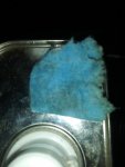
Finished cleaning the cylinder head. I used acetone as a final cleaning agent. Repeatedly wiped the head flange down until the blue rag would stay clean:
About 3 hours, total to clean the head. Besides just the flange, i also completely cleaned the head studs/bolts/nuts, inside the head below the flange, push rods and valve springs. Basically, anything that could contaminate the seal:
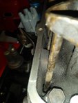
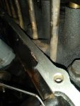
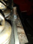
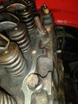
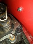
Before doing anything else, I removed these baffle screws and red lock tited them into place:
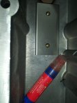
Sometimes they come shipped loose or stripped out. Don't want the engine to eat them!!
This engine's OEM valve cover used the two studded rocker arm bridges:
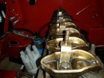
Easy enough to swap them out with the included non studded replacement parts:
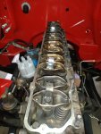
IIRC, 19 foot pounds to reinstall the bridge pivot bolts. I was pleased to see oil on the pivots, not caked up in crud.
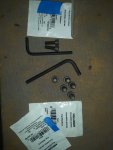
The hardware that comes with the valve cover is SAE, but the allen head bolts take metric allen wrenches? I also use metric flat washers on the SAE bolts due to the lack of clearance between the valve cover/bolt heads:
Finished cleaning the cylinder head. I used acetone as a final cleaning agent. Repeatedly wiped the head flange down until the blue rag would stay clean:
About 3 hours, total to clean the head. Besides just the flange, i also completely cleaned the head studs/bolts/nuts, inside the head below the flange, push rods and valve springs. Basically, anything that could contaminate the seal:
Before doing anything else, I removed these baffle screws and red lock tited them into place:
Sometimes they come shipped loose or stripped out. Don't want the engine to eat them!!
This engine's OEM valve cover used the two studded rocker arm bridges:
Easy enough to swap them out with the included non studded replacement parts:
IIRC, 19 foot pounds to reinstall the bridge pivot bolts. I was pleased to see oil on the pivots, not caked up in crud.
The hardware that comes with the valve cover is SAE, but the allen head bolts take metric allen wrenches? I also use metric flat washers on the SAE bolts due to the lack of clearance between the valve cover/bolt heads:
- City
- Biloxi
- State
- MS
Finally, time to mock the valve cover up. Sits flat on the head, no rocking or voids:
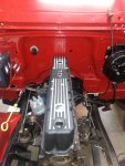
I installed only the rear bolt, and the front bolt hole would not line up with the threaded hole in the head:
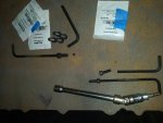
Used an SAE socket on a swivel to reach the rear bolt, close enough for quick in and outs. I also dug out my long metric allen wrenches. I usually keep these in my tool box, the tape lets me know they are metric LOL:
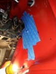
Put some tape on the firewall to protect the paint from the tools/cover scratching the paint:
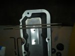
The cast aluminum is soft, so I just use hand files to enlarge the holes as needed:
I installed only the rear bolt, and the front bolt hole would not line up with the threaded hole in the head:
Used an SAE socket on a swivel to reach the rear bolt, close enough for quick in and outs. I also dug out my long metric allen wrenches. I usually keep these in my tool box, the tape lets me know they are metric LOL:
Put some tape on the firewall to protect the paint from the tools/cover scratching the paint:
The cast aluminum is soft, so I just use hand files to enlarge the holes as needed:
- City
- Biloxi
- State
- MS
Spanks, I was curious if you were still seeing movement in the steering box after installing the MORE bracket, and if that was the reason for the brace?
No, no movement. Just cheap insurance. In my opinion once you go up to even 33" tires, I would run a HD box mount and the cross over brace. The stock steering boxes are pretty strong, so I usually double brace the box into place, just to be safe.
- City
- Biloxi
- State
- MS
After filing the front hole, I installed the front and rear bolts to hold the cover in place and checked the alignment of the other 5 bolt holes to cylinder holes.
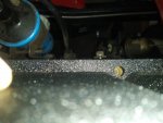
Passenger side back OK:
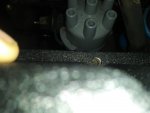
Passenger side middle OK:
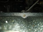
Passenger front OK:
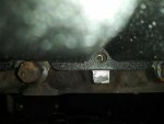
Driver side rear OK:
Driver side front needs some file work:
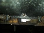
Filed the front down a hair more:
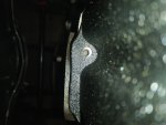
Checked the hole on the driver side front that was giving me issues:
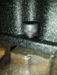
Still too tight, note where bolt threads cut into the aluminum, showing me where to file:
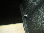
After that last bit of filing, cover fit correctly, all 7 bolts in.
I also checked to make sure the supplied bolts would work OK. They will. Sometimes you can use longer bolts depending on the depth of the threaded holes in the head. Just random thoughts of a madman.
Passenger side back OK:
Passenger side middle OK:
Passenger front OK:
Driver side rear OK:
Driver side front needs some file work:
Filed the front down a hair more:
Checked the hole on the driver side front that was giving me issues:
Still too tight, note where bolt threads cut into the aluminum, showing me where to file:
After that last bit of filing, cover fit correctly, all 7 bolts in.
I also checked to make sure the supplied bolts would work OK. They will. Sometimes you can use longer bolts depending on the depth of the threaded holes in the head. Just random thoughts of a madman.

- City
- Livingston
- State
- AL
No, no movement. Just cheap insurance. In my opinion once you go up to even 33" tires, I would run a HD box mount and the cross over brace. The stock steering boxes are pretty strong, so I usually double brace the box into place, just to be safe.
Gotcha! Cheap insurance is the best-

I upgraded to the MORE bracket on my 7, and, wow, it hasn't budged! But granted, I'm only running 31's. Given my plan to use 33's on my 8, I'll keep that in mind.

- City
- Biloxi
- State
- MS
Finally satisfied that the new valve cover/bolts will fit correctly, time to glue the gasket down.
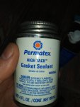
I use this stuff to glue the gasket to the valve cover:
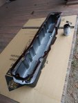
Draped the gasket over the valve cover to put a thin coat on it. Make sure you coat the side of the gasket that goes on the valve cover:
Put a thin coat on the valve cover:
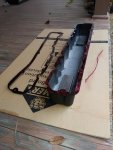
Stuff is very messy/stringy, wear old clothes. Acetone will clean it up. Note the strings of the stuff on the card board, it is kind of messy.
Let the stuff tack up 10 minutes, stuck the gasket to the cover, flipped the assembly over on a clean piece of cardboard, put a tool box on top to help glue it all together:
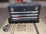
This stuff does a great job of glueing the gasket in place, no smoosh outs:
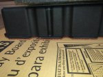
Let that sit for an hour. Put this stuff on the bottom of the gasket to help seal it to the head, I love this stuff:
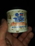
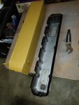
I use this stuff to glue the gasket to the valve cover:
Draped the gasket over the valve cover to put a thin coat on it. Make sure you coat the side of the gasket that goes on the valve cover:
Put a thin coat on the valve cover:
Stuff is very messy/stringy, wear old clothes. Acetone will clean it up. Note the strings of the stuff on the card board, it is kind of messy.
Let the stuff tack up 10 minutes, stuck the gasket to the cover, flipped the assembly over on a clean piece of cardboard, put a tool box on top to help glue it all together:
This stuff does a great job of glueing the gasket in place, no smoosh outs:
Let that sit for an hour. Put this stuff on the bottom of the gasket to help seal it to the head, I love this stuff:
- City
- Biloxi
- State
- MS
And finished and bolted down:
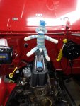
Snugged all 7 bolts down, no blow outs:
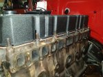
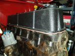
Before doing the final install, I did a few trial runs. It is a PIA to get the cover in place sometimes. This heater box stud can be problematic.
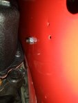
If the clearance is too tight, I would loosen up the transmission mount(s), jack up the transfer case to level the engine, you will gain some more room.
Valve cover gaskets on a 258 are a major PIA project. I always take my time/OCD to prevent leaks. I put over 30,000 miles on one of these valve covers on my red Scrambler and it never leaked. A piston skirt cracked, but the valve cover was still dry LOL.
I recently installed one of these on my stock '85 CJ7. That has a serpentine belt AND all the OEM emissions/feedback carb stuff. That took me two long days. That's why I don't cut corners when messing with them, a premature leak will bring the suck.
Snugged all 7 bolts down, no blow outs:
Before doing the final install, I did a few trial runs. It is a PIA to get the cover in place sometimes. This heater box stud can be problematic.
If the clearance is too tight, I would loosen up the transmission mount(s), jack up the transfer case to level the engine, you will gain some more room.
Valve cover gaskets on a 258 are a major PIA project. I always take my time/OCD to prevent leaks. I put over 30,000 miles on one of these valve covers on my red Scrambler and it never leaked. A piston skirt cracked, but the valve cover was still dry LOL.
I recently installed one of these on my stock '85 CJ7. That has a serpentine belt AND all the OEM emissions/feedback carb stuff. That took me two long days. That's why I don't cut corners when messing with them, a premature leak will bring the suck.
- City
- Biloxi
- State
- MS
Getting ready to install the intake and exhaust manifolds. These do not need to be removed to change the valve cover gasket, I removed them because all the bolts were loose, and to eliminate any potential leaks before I eventually try to tune this thing up, once it is finally running again. Cheap insurance.
The intake/exhaust manifold gasket kit came with the two gaskets for the intake heater, located on the bottom of the intake:
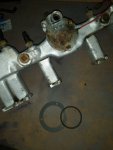
Good thing I checked, the rubber gasket inside the intake was no longer sealing.
Heater removed:
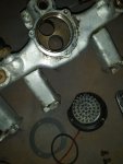
I reinstalled it all, after cleaning it up. Used stainless steel bolts, so I used anti seize to prevent problems with the stainless/aluminum potential reaction.
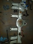
Cleaned up the sealing surface:
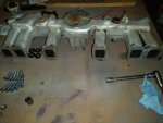
Cleaned up the exhaust manifold sealing surfaces:
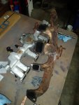
And this is when the fun started.
The intake/exhaust manifold gasket kit came with the two gaskets for the intake heater, located on the bottom of the intake:
Good thing I checked, the rubber gasket inside the intake was no longer sealing.
Heater removed:
I reinstalled it all, after cleaning it up. Used stainless steel bolts, so I used anti seize to prevent problems with the stainless/aluminum potential reaction.
Cleaned up the sealing surface:
Cleaned up the exhaust manifold sealing surfaces:
And this is when the fun started.
- City
- Biloxi
- State
- MS
Dry fitting the exhaust manifold:
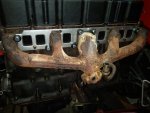
And this is when the problems started. This engine has been missing the rear most exhaust manifold stud since Tommy bought it. Never knew why. All the threaded holes in the head are fine. Head is fine.
Well, I have never seen this before, but the exhaust manifold is somehow severely warped/misshapen, I can't even get all the bolts past it into the head!!
Two center bolts installed, the next outer set of holes is not even close!!
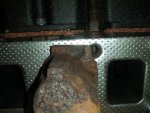
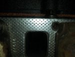
The two outer most stud holes are not even close!!
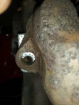
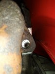
Now, I can force/pivot the manifold and force the issue, but still can not get the manifold to fit right, and get the rear most stud in place.
Glad I did not waste too much time on it, this manifold is going in the trash. Besides the warped issue, one of the collector studs is FUBAR, and the other collector stud hole has been incorrectly drilled/tapped.
I will order a new exhaust manifold from NAPA tomorrow. Live to fight another day.
While I had the scrap manifold bolted to the engine, I was able to get the EGR tube out of it. PB Blaster, repeatedly smacked the 1" wrench with a hammer, it came out:
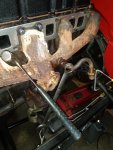
But, the fitting that threads into the exhaust manifold is 100% rust fused to the tube, and the threads look iffy at best. Not going to waste time trying to repair it. It is such a PIA trying to reinstall this tube into the two manifolds IF both fitting can pivot around the tube, I am not even going to attempt to try to reinstall this tube with one fitting fused to the tube.
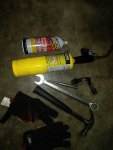
Good news, I still have the tube that came out of my green Scrambler. I installed a new tube into it a few years ago, kept the original tube. The exhaust manifold fitting on this one was frozen to the tube, too. But, did not look near as bad. 30 minutes with a torch, 1/2 a can of PB Blaster, and getting the exhaust manifold fitting glowing red hot/quenched in PB Blaster four times, I now have a good EGR cross over tube:
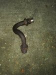
Hopefully I won't have to wait too long on the replacement exhaust manifold. Still lots of other under hood stuff to work on.
That's it for now.
And this is when the problems started. This engine has been missing the rear most exhaust manifold stud since Tommy bought it. Never knew why. All the threaded holes in the head are fine. Head is fine.
Well, I have never seen this before, but the exhaust manifold is somehow severely warped/misshapen, I can't even get all the bolts past it into the head!!
Two center bolts installed, the next outer set of holes is not even close!!
The two outer most stud holes are not even close!!
Now, I can force/pivot the manifold and force the issue, but still can not get the manifold to fit right, and get the rear most stud in place.
Glad I did not waste too much time on it, this manifold is going in the trash. Besides the warped issue, one of the collector studs is FUBAR, and the other collector stud hole has been incorrectly drilled/tapped.
I will order a new exhaust manifold from NAPA tomorrow. Live to fight another day.
While I had the scrap manifold bolted to the engine, I was able to get the EGR tube out of it. PB Blaster, repeatedly smacked the 1" wrench with a hammer, it came out:
But, the fitting that threads into the exhaust manifold is 100% rust fused to the tube, and the threads look iffy at best. Not going to waste time trying to repair it. It is such a PIA trying to reinstall this tube into the two manifolds IF both fitting can pivot around the tube, I am not even going to attempt to try to reinstall this tube with one fitting fused to the tube.
Good news, I still have the tube that came out of my green Scrambler. I installed a new tube into it a few years ago, kept the original tube. The exhaust manifold fitting on this one was frozen to the tube, too. But, did not look near as bad. 30 minutes with a torch, 1/2 a can of PB Blaster, and getting the exhaust manifold fitting glowing red hot/quenched in PB Blaster four times, I now have a good EGR cross over tube:
Hopefully I won't have to wait too long on the replacement exhaust manifold. Still lots of other under hood stuff to work on.
That's it for now.
- City
- Biloxi
- State
- MS
The new exhaust manifold I ordered from NAPA showed up the other day:
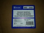
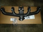
I guess they are kind of "one size fits all", in regards to the air injection ports, which I don't need. It did come with plugs for the air injection ports, 02 sensor port, and the EGR crossover tube, so that was nice of them!!!
The O2 sensor plug and the EGR crossover tube port plug also came with "crush" washers:
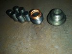
IIRC, the air injection ports are standard pipe thread/plugs, but I could be wrong.
It has been too cold to paint, but tomorrow it will warm up over 60 so I will spray some paint on the new exhaust manifold. Just going to use regular engine enamel, rated for 650 degrees. It is really the thought that counts, I have not really had any long term success with any rattle can stuff sticking to an exhaust manifold. We will see....
I did mock up the new manifold to the cylinder head, and it fits/lines up perfect. So, the old manifold was definitely FUBAR.
While waiting to install the manifolds, bolted on some easy parts.
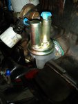
New fuel pump and gasket:
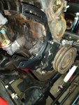
Alternator bracket:
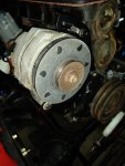
And the alternator:
I painted the original bare steel brackets mainly to keep them from rusting. Not really trying to make this look like a "new engine", mainly just cleaning everything up and painting a few parts to preserve them. Engine will have some patina, for sure, but will be better then before. Being clean will also help me find any leaks easier!!
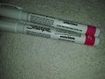
Did some "arts and crafts" - While it was still easily accessible, I used some oil based/enamel paint pens, colored in some of the timing marks/numbers/harmonic balancer line to make future tune up work easier. Looks good now, will have to see how durable it is.
That's it for now.
I guess they are kind of "one size fits all", in regards to the air injection ports, which I don't need. It did come with plugs for the air injection ports, 02 sensor port, and the EGR crossover tube, so that was nice of them!!!
The O2 sensor plug and the EGR crossover tube port plug also came with "crush" washers:
IIRC, the air injection ports are standard pipe thread/plugs, but I could be wrong.
It has been too cold to paint, but tomorrow it will warm up over 60 so I will spray some paint on the new exhaust manifold. Just going to use regular engine enamel, rated for 650 degrees. It is really the thought that counts, I have not really had any long term success with any rattle can stuff sticking to an exhaust manifold. We will see....
I did mock up the new manifold to the cylinder head, and it fits/lines up perfect. So, the old manifold was definitely FUBAR.
While waiting to install the manifolds, bolted on some easy parts.
New fuel pump and gasket:
Alternator bracket:
And the alternator:
I painted the original bare steel brackets mainly to keep them from rusting. Not really trying to make this look like a "new engine", mainly just cleaning everything up and painting a few parts to preserve them. Engine will have some patina, for sure, but will be better then before. Being clean will also help me find any leaks easier!!
Did some "arts and crafts" - While it was still easily accessible, I used some oil based/enamel paint pens, colored in some of the timing marks/numbers/harmonic balancer line to make future tune up work easier. Looks good now, will have to see how durable it is.
That's it for now.
- City
- Biloxi
- State
- MS
Starter bolting on a bunch of parts today. Takes days to clean up, find, and paint stuff, a few hours to assemble.
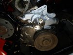
Water pump:
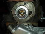
Thermostat:
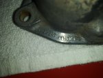
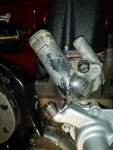
Original thermostat housing:
Installed:
Replacement power steering return and supply lines:
Don't throw out the o-rings:
Pre-lubing the o-rings in power steering fluid:
Got both lines installed, plus the frame mounted clips. The pressure line takes a bit of hand tweaking to get it bent 100% correctly to go in. Be careful with the fittings, it would really suck to strip out one of the ports in the steering box. Having the grill/radiator out of the way makes this a piece of cake.
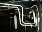
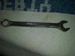
The OEM line fittings used SAE wrenches, two different sizes IIRC. Both these replacement lines used the same metric wrench:
Water pump:
Thermostat:
Original thermostat housing:
Installed:
Replacement power steering return and supply lines:
Don't throw out the o-rings:
Pre-lubing the o-rings in power steering fluid:
Got both lines installed, plus the frame mounted clips. The pressure line takes a bit of hand tweaking to get it bent 100% correctly to go in. Be careful with the fittings, it would really suck to strip out one of the ports in the steering box. Having the grill/radiator out of the way makes this a piece of cake.
The OEM line fittings used SAE wrenches, two different sizes IIRC. Both these replacement lines used the same metric wrench:
- City
- Biloxi
- State
- MS
Mocking up, finding the correct bolts, some power steering brackets. Steel plates to block and water pump, all SAE bolts:
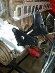
These two aluminum clam shell parts wrap around the reservoir, all metric bolts here, except the silver bolt threaded into the back of one of the aluminum brackets:
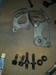
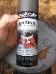
It finally warmed up to over 60 around 11am. Used this paint on the new exhaust manifold. The color actually matches the bare cast metal pretty well.
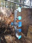
Hanging up in the paint booth:
And painted:
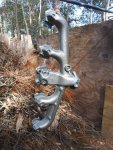
Like I said, the color is almost the same as the raw metal!!
I had to reuse the the old power steering pump reservoir, installed a new pump. Could not get a pump/reservoir assembly from NAPA this time. No big deal.
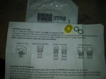
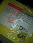
The new pump will come with some o-rings, most of which you won't need:
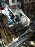
On the new pump, they torqued the damn pressure port down, could not get it broke free on the bench. So, assembled the bare pump to some of the power steering pump brackets to secure it so I could get the pressure port out:
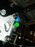
The pressure port has to come out so the pump can go inside the reservoir can, then the port goes back in. The pressure port has the green plastic cap stuck into it:
Got the port out. Forgot to take a picture. Basically, two o-rings from the packet go in the back of the pump to seal the mounting studs. The pump seals to the front of the can with a continuous o-ring that is already on the pump. Lube the o-rings, line up the pump in the reservoir. Use the two mounting studs and the pressure port to pull the can and pump together:
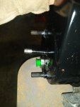
Note the difference between the two mounting studs. The lower stud has a built in spacer on it.
These two aluminum clam shell parts wrap around the reservoir, all metric bolts here, except the silver bolt threaded into the back of one of the aluminum brackets:
It finally warmed up to over 60 around 11am. Used this paint on the new exhaust manifold. The color actually matches the bare cast metal pretty well.
Hanging up in the paint booth:
And painted:
Like I said, the color is almost the same as the raw metal!!
I had to reuse the the old power steering pump reservoir, installed a new pump. Could not get a pump/reservoir assembly from NAPA this time. No big deal.
The new pump will come with some o-rings, most of which you won't need:
On the new pump, they torqued the damn pressure port down, could not get it broke free on the bench. So, assembled the bare pump to some of the power steering pump brackets to secure it so I could get the pressure port out:
The pressure port has to come out so the pump can go inside the reservoir can, then the port goes back in. The pressure port has the green plastic cap stuck into it:
Got the port out. Forgot to take a picture. Basically, two o-rings from the packet go in the back of the pump to seal the mounting studs. The pump seals to the front of the can with a continuous o-ring that is already on the pump. Lube the o-rings, line up the pump in the reservoir. Use the two mounting studs and the pressure port to pull the can and pump together:
Note the difference between the two mounting studs. The lower stud has a built in spacer on it.
- City
- Biloxi
- State
- MS
Used a few brackets to hold the pump/reservoir assembly steady, torqued the two studs and the pressure port to spec:
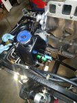
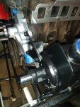
General reference pictures of how all the power steering pump brackets assemble to the pump/reservoir assembly:
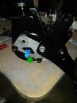
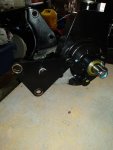
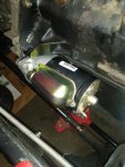
After all that, quick easy job, bolted the starter into place:
General reference pictures of how all the power steering pump brackets assemble to the pump/reservoir assembly:
After all that, quick easy job, bolted the starter into place:
- City
- Biloxi
- State
- MS
Time to install the two proportioning valve to master cylinder brake lines:
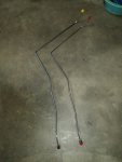
These are the same lines installed on my green Scrambler, you can barely see them/get to them on a completely assembled vehicle:
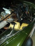
That's why I waited till I had the front clip tore off of the red one before I tried to install them, much more access!!!
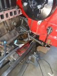
Cleaned out, blew out the threaded ports in the proportioning valve. Larger tube goes toward the rear of the valve. I installed it first, then the forward line:
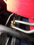
Got both lines installed, no real problem, but even with this much stuff out of the way, still a PIA. Took my time, got comfortable, made sure I did not cross thread either line. I actually swung the lines way out of final position to get the threaded ends to line up with the ports in the valve. Hand started both fittings, then just twisted them in. Then, swung the lines into position.
Before trying to either tighten the lines to the proportioning valve or installing the master cylinder, I secured the two lines to the heat shield with some metal line clamps:
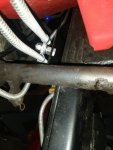
This does not match OEM 100%, but works perfectly. You need to support these lines before trying to do the final tightening. I ran a bolt from the bottom of the heat shield up, secured it with a nut, and now I have a nice mounting stud for the two line clamps. Easier then tring to run bolts down through the clamps into the heat shield.
That's it for now!!!
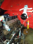
These are the same lines installed on my green Scrambler, you can barely see them/get to them on a completely assembled vehicle:
That's why I waited till I had the front clip tore off of the red one before I tried to install them, much more access!!!
Cleaned out, blew out the threaded ports in the proportioning valve. Larger tube goes toward the rear of the valve. I installed it first, then the forward line:
Got both lines installed, no real problem, but even with this much stuff out of the way, still a PIA. Took my time, got comfortable, made sure I did not cross thread either line. I actually swung the lines way out of final position to get the threaded ends to line up with the ports in the valve. Hand started both fittings, then just twisted them in. Then, swung the lines into position.
Before trying to either tighten the lines to the proportioning valve or installing the master cylinder, I secured the two lines to the heat shield with some metal line clamps:
This does not match OEM 100%, but works perfectly. You need to support these lines before trying to do the final tightening. I ran a bolt from the bottom of the heat shield up, secured it with a nut, and now I have a nice mounting stud for the two line clamps. Easier then tring to run bolts down through the clamps into the heat shield.
That's it for now!!!
- City
- Biloxi
- State
- MS
Where did you order your lines from? Been looking at the omni max stuff.. liked the stainless line to the calipers as well.
Tommy ordered these line a long time ago, but either Classic Tube or Inline Tube. The flexible front brake lines came with the Rubicon Express 4.5" lift kit.