• Notice for iPhone users: DO NOT use the image size reduction option when uploading photos to the forum. This causes portrait images to post as landscape. We have added a warning to the image insert pop-up as well.

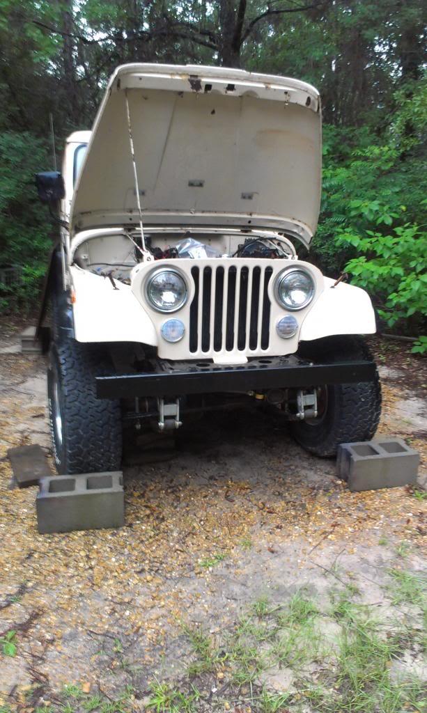
Spankrjs' 1984 Long Term Project

you are feeling terribly sick... call work and let them know. (I just bought you some time) I smrt.

LOL:thumbsup:

Complete rainout, Thursday-Sunday:banghead::(

I was able to do some stuff underneath, so not a complete waste of time:shrug:

Will post some pictures/updates later:thumbsup:
 
OK, update from the 4th of July weekend.

A bunch of this stuff isn't too interesting, but it details my ways of overcoming certain "issues" dealing with the swapped in TBI 350.

I previously ran my fuel return and supply lines down the passenger side frame rail. I made new lines, 3/8 supply and 5/16 return, out of stainless, to feed the TBI 350. My engine has hard lines that come from the TB and dump out on this side of the engine.

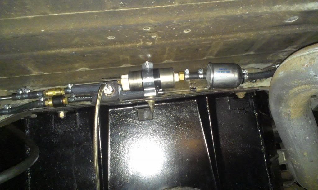
For the supply, I cut the factory line where it crosses the cross member. I left enough space to mount my filter and pump. For the return, this is what I did:

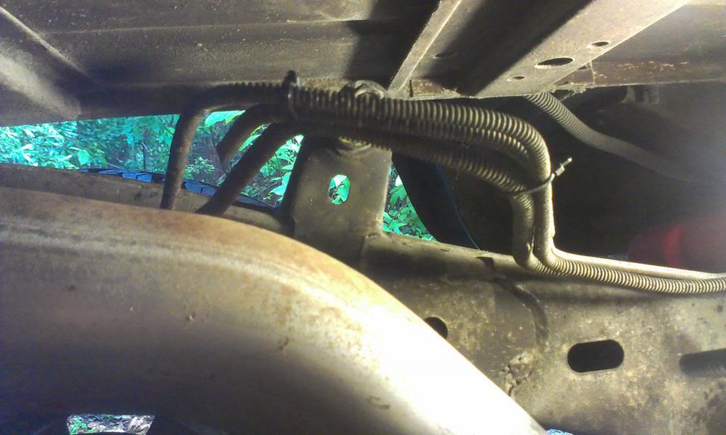
I cut the factory return line here, which is on the passenger side frame rail from the factory:

IMAG1266_zps9a07c77e-1.jpg


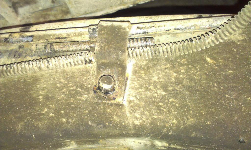
Inserted a piece of scrap tubing into the factory clamp. Not the prettiest thing, but it helps secure the remaining rear brake line/vent line securely in the clamps, and holds them in position. I might completely remove the unused stock return line in the future, it is of no use now.

IMAG1265_zpsc51186eb-1.jpg


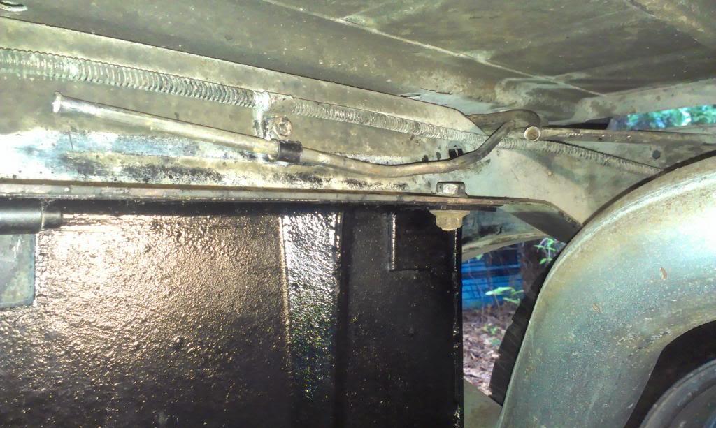
And then bent the line 90 degrees at the cross member. The lower, longer line secured by the clamp, is the return line. The shorter, higher up line is the stock supply line.

IMAG1264_zps2c3bc9d3-1.jpg


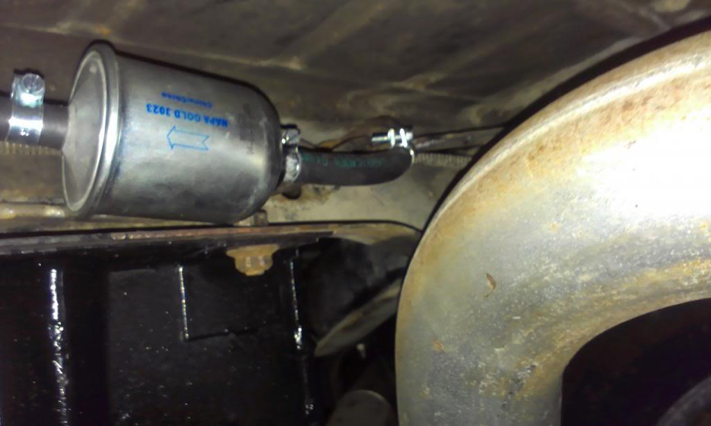
A short piece of FI hose connects the factory supply line to my new filter.

IMAG1268_zps36ee48f4-1.jpg


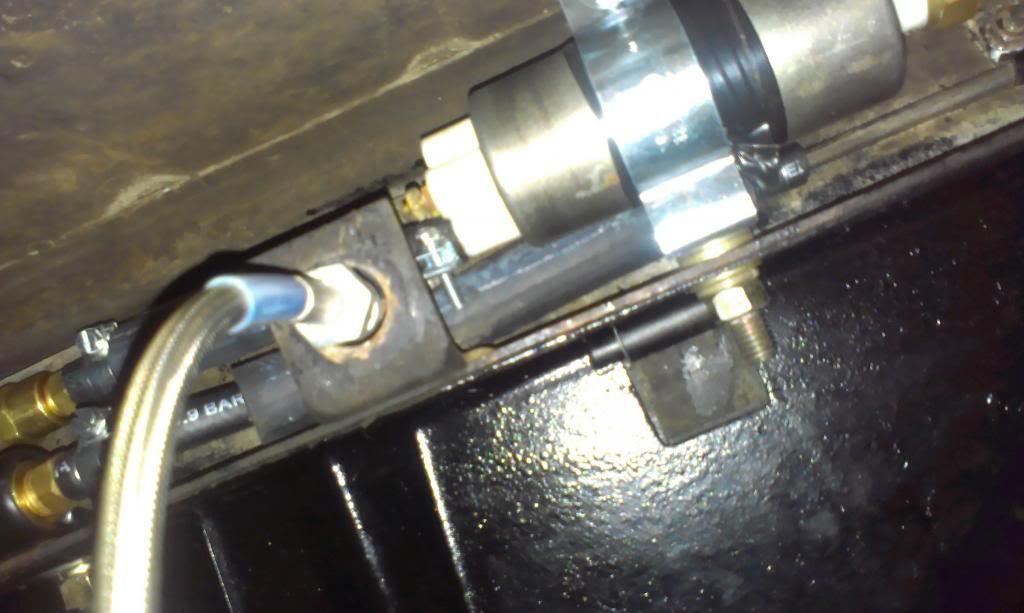
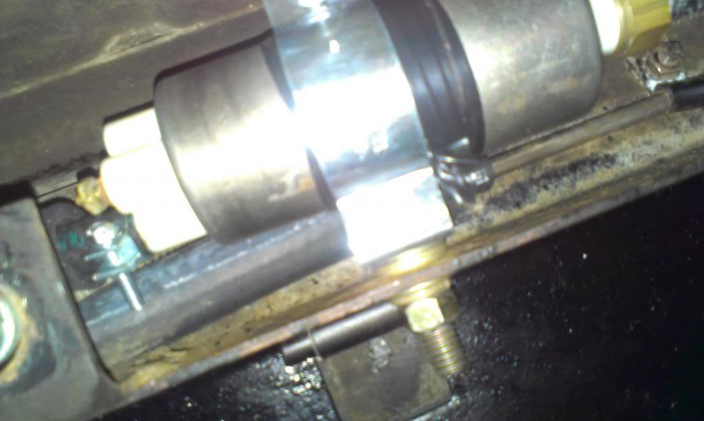
And another short piece of FI hose connects the filter to the electric pump. I used an 1-1/2 conduit clamp to secure the fuel pump to the cross member. I used one of the existing holes in the cross member for the conduit clamp bolt. I wrapped electric tape around the pump to "insulate it/eliminate annoying noise which might result form the metal pump being mounted directly to the metal clamp.

IMAG1270_zps2f5bc61a-1.jpg


In the above picture, after the pump, you will notice a brass thing. This is my 5/16 to 3/8 adapter. The CJ tank has a 5/16 supply line, my filter is 5/16, and the fuel pump is 5/16. I jumped up to 3/8 here, which is what my new long supply line is, which matches the TB 3/8 supply line,

You will also notice another brass adapter on the return line. Same thing. The CJ uses a 1/4 return line to the tank. The GM engine/my new return line are 5/16. Since this area is so "busy" anyway, with the pump/filter, I figured I would do my adapting here.

I read "conflicting" information as to what size return/supply lines to use. Some people say the factory line sizes are fine, others say you must go up in size. Since I was making new lines anyway, I jumped up to the 3/8 supply and 5/16 return lines. This is what GM uses. I still use the factory 5/16 supply and 1/4 return line before the pump. You have to, since this is what the sending unit uses, unless you buy a custom sending unit. Since 90% of my lines match the GM sizes, I guess I mitigated any potential "choke" point.


A few close ups, showing the FI clamps I used. I also "sleeved" the rubber lines at chafe points with pieces of larger ID heater hose. I also secured the hard lines to the cross member with rubber lined clamps.

IMAG1272_zps8388af38-1.jpg


IMAG1273_zps3f31e810-1.jpg


Since this Scrambler has a full hard top, which doesn't leak, I was able to do all of this work while it was raining. Sitting on a piece of plywood, I stayed pretty dry!!!!
 
I moved on to my transmission mount next.

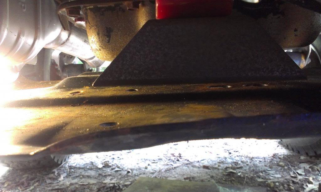
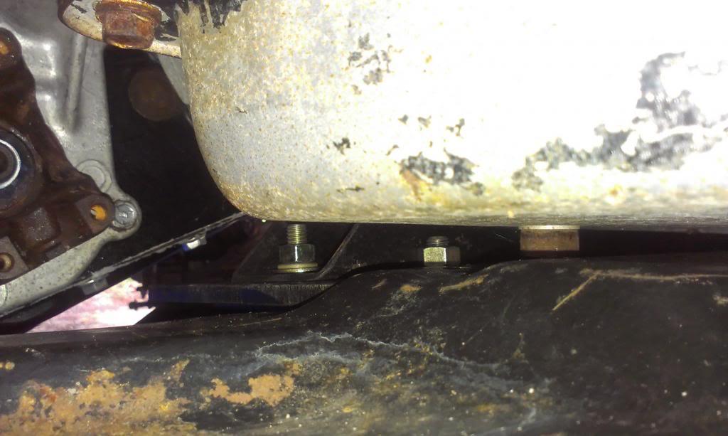
My 350 has a 700R4 bolted to the back of it. It uses an older Novak adapter to connect the transmission to the transfer case. This adapter is very different then the newer ones, in regards to the transmission mount mounting. Basically, the red polyurethane transmission mount bolts directly to the aluminum adapter. IIRC, this is a common, standard GM 2wd truck mount. The previous owner made the wide "foot" piece that attaches to the bottom of the polyurethane mount. I like this wide foot, so I used it.

OK, that is all fine and dandy, but how to mount the foot to the skid plate, without drilling a bunch of holes? Also, where the "foot" lands is on a very uneven part of the skid plate. Basically, 1/2 the foot lands on the upper level, the other 1/2 lands on the bottom level. Also, the foot does not even touch the skid plate, it sits too high.

IMAG1275_zps68ae91fe-1.jpg


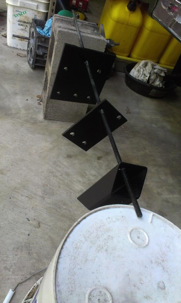
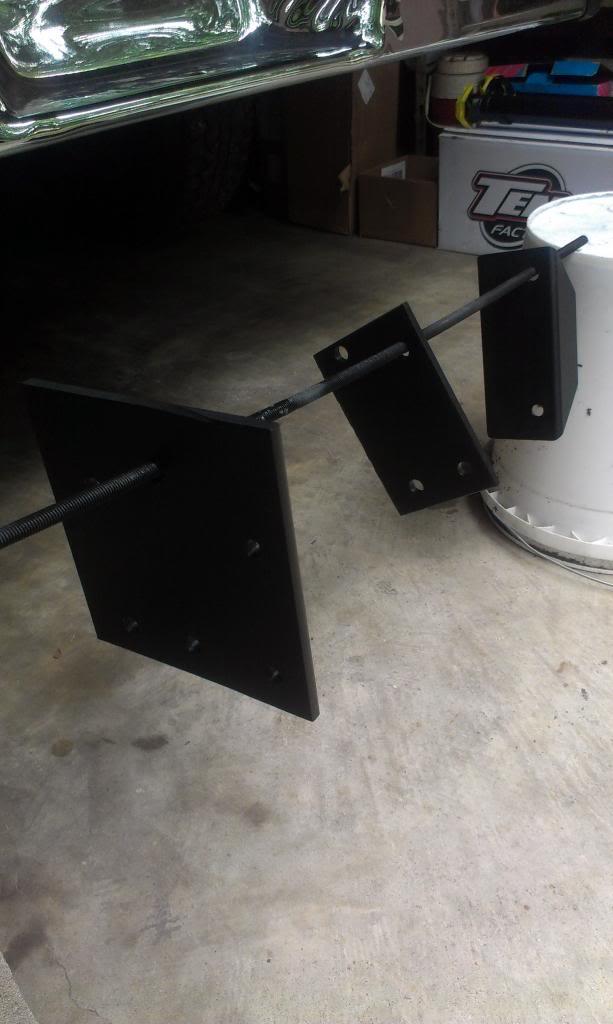
I made a "leveler plate", out of 3/16" plate steel, to "level" up the bottom of the skid plate. I then used a piece of 1/4" steel plate to make a mounting plate for the "foot".

The pictures below show my 3 piece transmission mount assembly after I painted them. It took a few hours of cutting, marking, drilling, testing, etc.. before it would work.

IMAG1278_zpsde1ea446-1.jpg


IMAG1292_zpsc431ae31-1.jpg


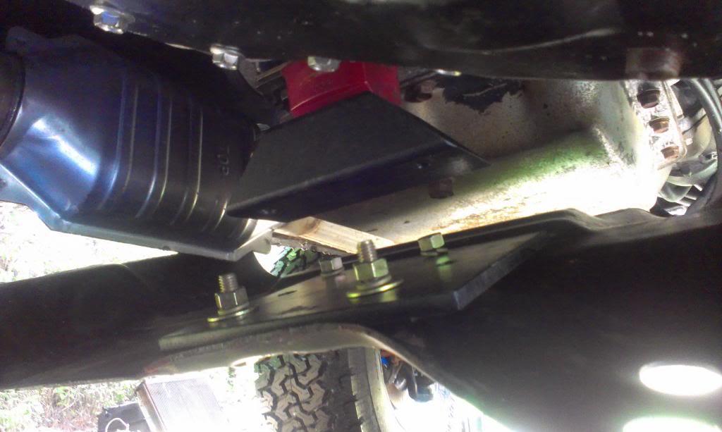
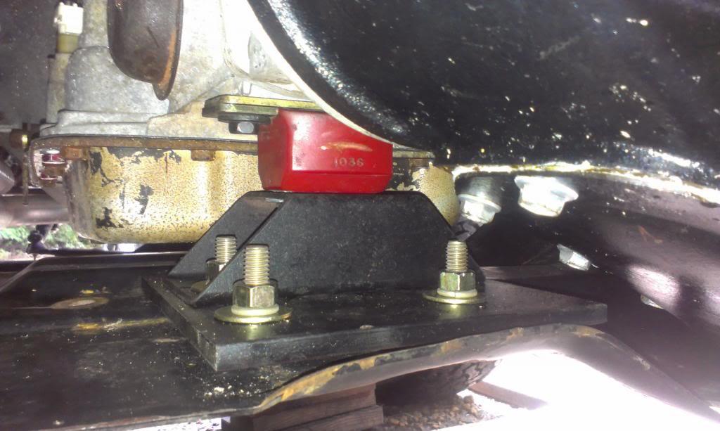
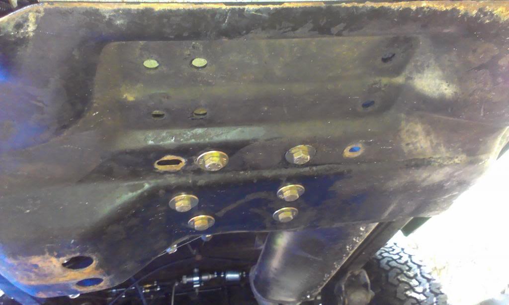
My "leveler plate" bolts to the skid plate using two existing holes. The "mounting plate" attaches at the front and rear using existing holes. I only had to drill two new holes in the skid plate for the bolts that go through the skid plate, then through both plates, then into the "foot". I used 7/16" grade 8 bolts everywhere. All of my hole are 7/16", which means all these parts fit very snugly together.

The pictures explain it better.

A picture with the stock skid plate hanging down. The 1/4" mounting plate has already been set on top of the 3/16" leveler plate in this picture. The 4 mounting bolts are loosely secured.

IMAG1295_zps260d3b1f-1.jpg


And all bolted up. The 2 center bolts mount the foot to the plates/skid plate.

IMAG1297_zpsad75f81e-1.jpg


A picture from the front side, showing the shorter bolts used up front. There is less clearance on this end, due to the transmission pan.

IMAG1299_zps2b759e19-1.jpg


And from the bottom. I don't necessarily like having 6 bolt heads down there, but it works. Since I used thick plate steel, I can probably taper the holes and use "flush head" bolts. For now, it works.

IMAG1302_zps2623e18f-1.jpg


I am leaving this as it is for now. Once I get the Scrambler on level concrete, I can adjust the rear driveshaft angle, if necessary, by adding steel between the "foot" and the mounting plate. All in all, except for drilling two holes, I think it came out great, was not too "labor intense", and seems to be very sturdy. I can also go back and weld the plates to the skid plate for additional strength. I am not using a "torque arm" mount at this time. I don't think I need it. The engine mounts sit flat, so I do not think I will get too much "engine only twist". We will see..............


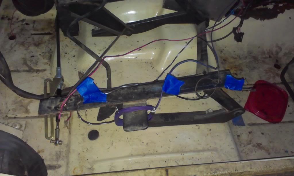
I then wired up my fuel pump. I ran new, 14 gauge ground/power wires through plastic tubing. I secured the tubing to one of the fuel rails using cable ties. I ran the tubing through a "body channel". I still need to hook these wires up to the secondary fuse panel that came with the TBI harness, located next to the battery, under the hood.

IMAG1303_zpsc203e1fb-1.jpg


IMAG1304_zpsf0e505ef-1.jpg
 
Keep in mind, I was trying to do all of this in between all of this!!!!!!!!!

IMAG1312_zps91c63ff2-1.jpg


IMAG1293_zpsb9b85b02-1.jpg


Since it rained pretty much all weekend, and I got tired of laying in mud, I decided to do some "above ground" work.

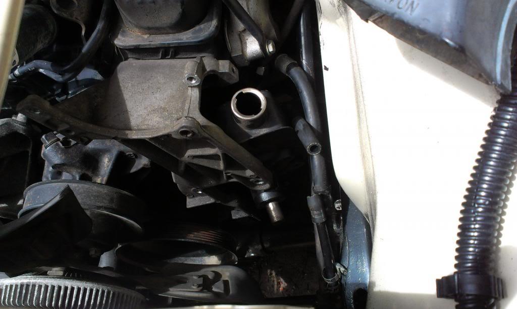
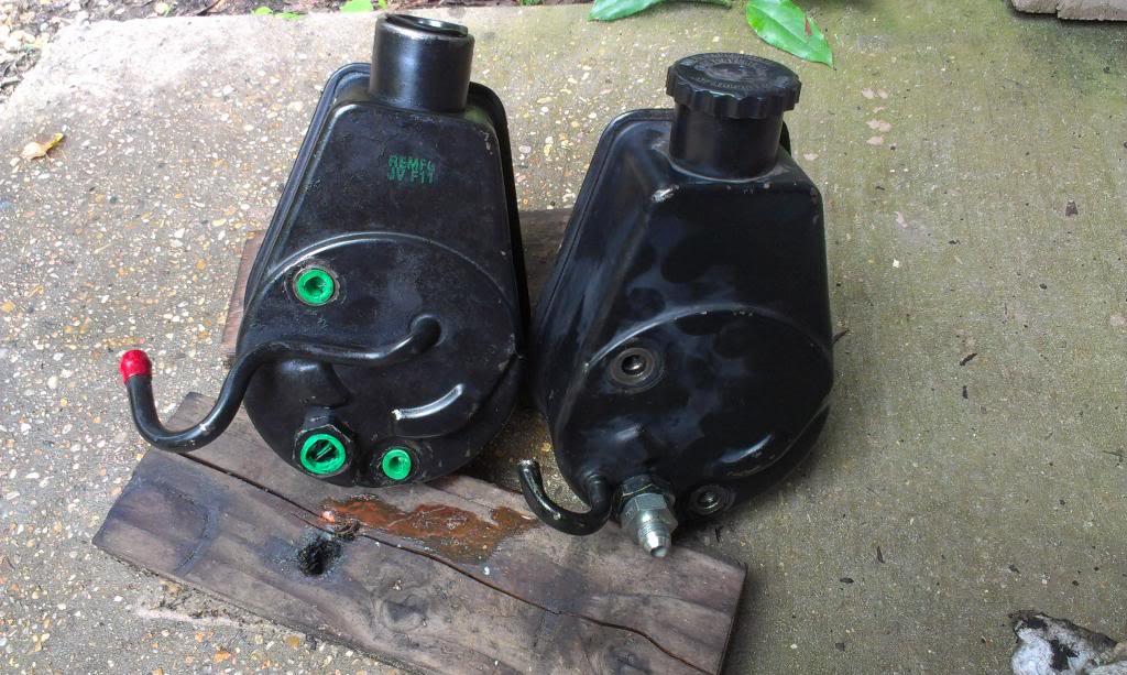
The power steering pump that came with this engine had a bunch of slack at the snout. I bought a new pump to replace it. The way the GM mount holds the pump, well, makes it a pain in the azz to change if the engine is in a narrow CJ. The pump wont slide out the side of the big bracket due to the steering shaft on one side, the top of the braket up top, the frame at the bottom, and the inside of the bracket on the other side. So, pull the bracket you say. Yes, but in order to pull the bracket, you have to take the bolts out of the pump. Not impossible, but fun!!!!!!!!!!!!

IMAG1305_zpsa3d7cb67-1.jpg


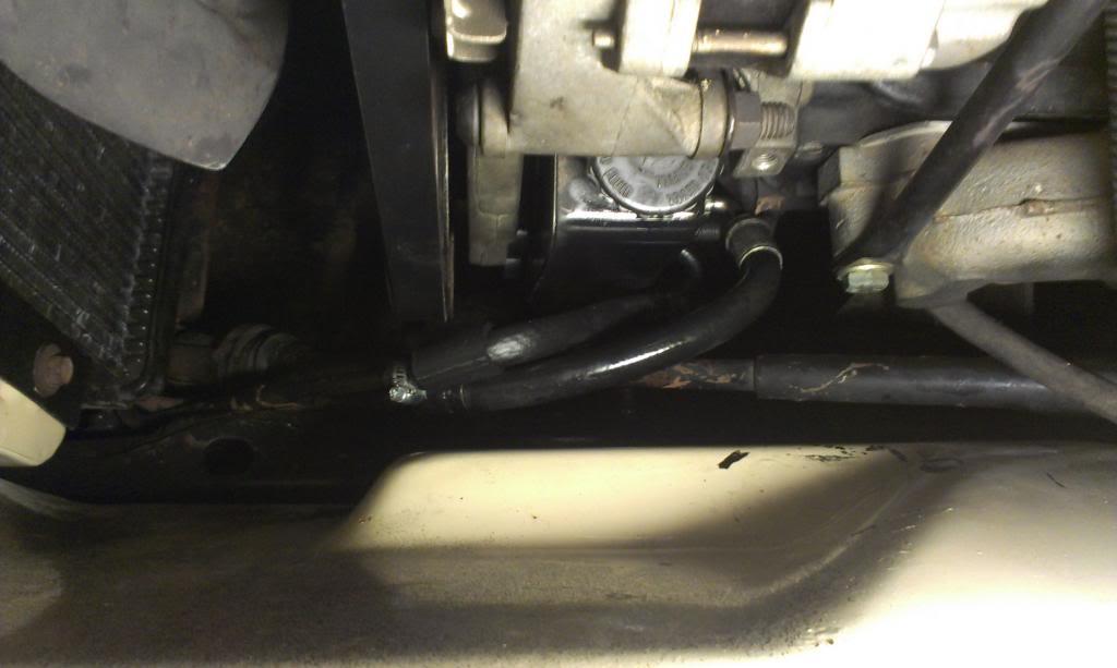
The pump I bought came with a reservoir. Of course, it was the wrong reservoir!!!! The reservoir that was installed had been modified at the return line pipe, so that it would clear the steering shaft. Easy enough, I put the new pump in the old reservoir, done deal. The PO already made a custom PS pressure line that looks good. I added a short piece of rubber ATF line and finished hooking up the return line.

IMAG1306_zpsb0386712-1.jpg


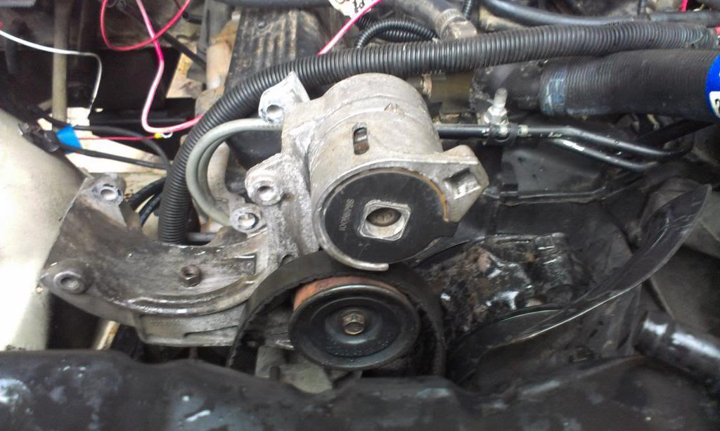
My existing tensioner pulley had a bad bearing. I was going to buy a whole new tensioner, but could not find the correct model. Since the "tensioner" part still feels great, I simply put a new bearing in the pulley. Easy $10 fix. I like those!!!

IMAG1310_zpsf1e31403-1.jpg


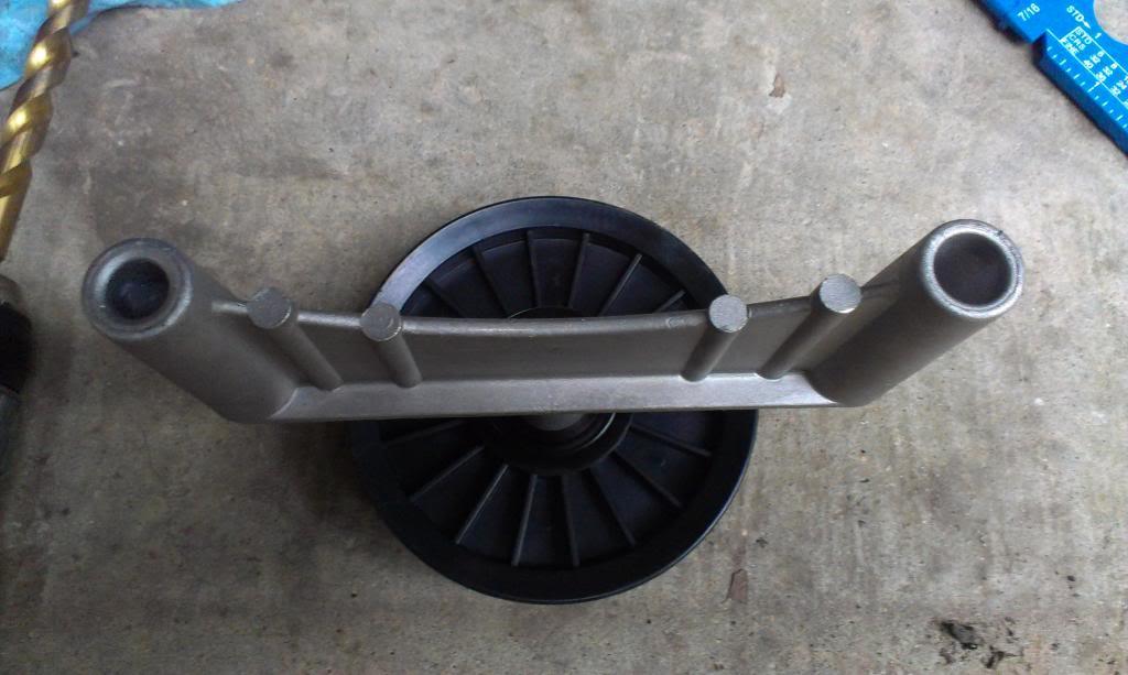
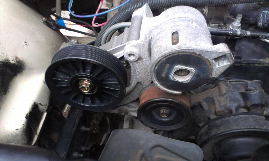
You will also note in the above picture that I am missing the AC compressor. AC would be nice, but I don't have the time to do all of that now. But, I need a pulley here to run the serpentine belt. Easy enough, I bought an "AC DELETE" pulley assembly. $35 fix, not too bad. EXCEPT - the part was made wrong!!!!!!!!! GM use 10mm bolts to secure the compressor to the bracket. I know this because the bracket has threaded "nuts" built into it to secure the compressor. The compressor delete assembly I bought had one of the mounting holes too small, the one on the left.

IMAG1313_zps0219595d-1.jpg


I do not want to go into another "MADE IN CHINA CRAP RANT", so I drilled the small hole out with a 7/16" bit, and it fit fine. NOTE - the bolts in the picture are too short. They are for mock up. I need to go buy (x2) 10mm 1.5 thread 115mm long bolts to finish this up.

IMAG1314_zpsb92c7b80-1.jpg


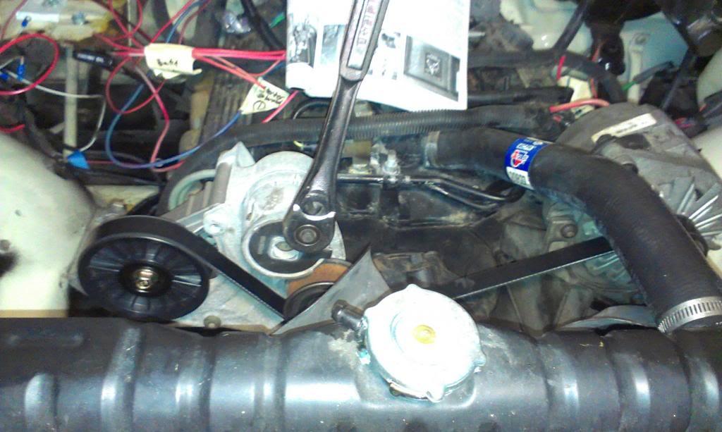
And after 3 trips to the store, I had the correct length belt!!!

IMAG1315_zpsab3bc11f-1.jpg


I assume it is the correct length, the tensioner is in the middle of its travel range.
 
Quick picture of the PS lines. Note the "chafe sleeve" to protect the return line from rubbing on the metal part of the pressure line.

IMAG1317_zpsbe137863-1.jpg


While under the hood, I finished hooking up the fuel supply/return lines.

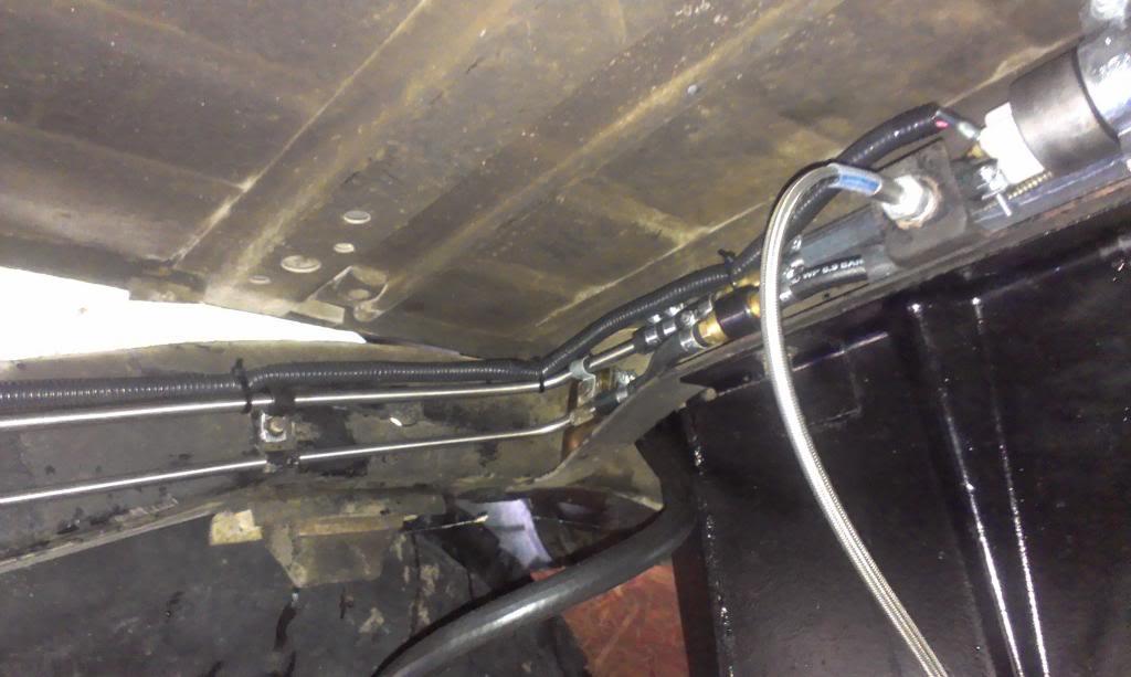
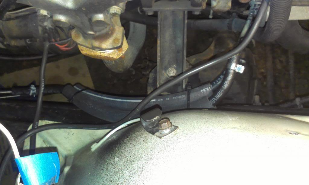
Overall shot, looking down from the passenger side fender. Note "chafe sleeves". I also left some "slack", to take up any engine movement.

IMAG1318_zpse9dde768-1.jpg


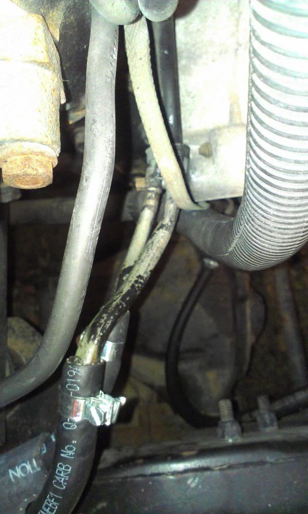
Close up where the lines hook on to the GM TB metal lines, behind/below the AC compressor bracket.

IMAG1319_zps0af1f23e-1.jpg


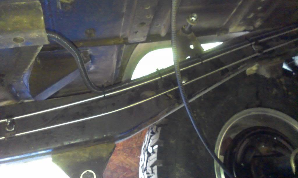
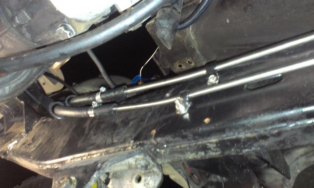
Looking up from the rear, where the lines hook up to my SS frame mounted lines.

IMAG1320_zps8c909a95-1.jpg


I am going to concentrate on the wiring next, so I can get the engine running.

That's it for now.
 
You will also note in the above picture that I am missing the AC compressor. AC would be nice, but I don't have the time to do all of that now. But, I need a pulley here to run the serpentine belt. Easy enough, I bought an "AC DELETE" pulley assembly. $35 fix, not too bad. EXCEPT - the part was made wrong!!!!!!!!! GM use 10mm bolts to secure the compressor to the bracket. I know this because the bracket has threaded "nuts" built into it to secure the compressor. The compressor delete assembly I bought had one of the mounting holes too small, the one on the left.

IMAG1313_zps0219595d-1.jpg


I do not want to go into another "MADE IN CHINA CRAP RANT", so I drilled the small hole out with a 7/16" bit, and it fit fine. NOTE - the bolts in the picture are too short. They are for mock up. I need to go buy (x2) 10mm 1.5 thread 115mm long bolts to finish this up.

IMAG1314_zpsb92c7b80-1.jpg


And after 3 trips to the store, I had the correct length belt!!!

IMAG1315_zpsab3bc11f-1.jpg


I assume it is the correct length, the tensioner is in the middle of its travel range.

Where did you get the "AC DELETE" pulley assembly and can you tell me the part number? That is exactly what I need! I never knew they even made a part like that!
 
And after 3 trips to the store, I had the correct length belt!!!

3 trips? not bad! I did 5... each time taking home 4 or 5 belts. Its good to know the parts guy. "here take all of these and pay when you find one that fits."

There are marks to line up on the tensioner so you know you have the correct tension.
 
Where did you get the "AC DELETE" pulley assembly and can you tell me the part number? That is exactly what I need! I never knew they even made a part like that!

Dorman part# 34152, available at O'Reily's, Advance Auto, Autozone etc:thumbsup: Only around $35:wave:

GM part# 55980, probably more expensive:shrug:
NAPA part# 6601802

Might be able to find one in a junkyard, too.

Make sure you still have your compressor bolts, it is hard to find the correct length/size:eek:

Mine takes a 115mm long, 10mm bolt, 1.5 thread. NAPA sells a 120mm, which is too long, but can be cut down. The longest Lowes sells is 100mm. Or, get them from a junkyard:thumbsup:

You will use the same belt as an AC equipped vehicle.
 
Good work!

Appreciate it Randy:thumbsup::cheers::wave:

3 trips? not bad! I did 5... each time taking home 4 or 5 belts. Its good to know the parts guy. "here take all of these and pay when you find one that fits."

There are marks to line up on the tensioner so you know you have the correct tension.

:rotfl: on the belt issue, I know what you mean:thumbsup:

I saw the marks on the tensioner/AC compressor bracket. I will take a picture of where mine is at:thumbsup:
 
I started working on the wiring last night. Not the most exciting/visually stimulating work, but here are some pictures and information/questions/concerns!!

I basically have 3 major wiring "areas":

1) TBI harness - not too bad, but have a few grey areas
2) Chevy start/charge system - not too familiar with this, doesn't look too bad
3) Tying the the TBI/start/charging system to CJ - not too bad, I hope

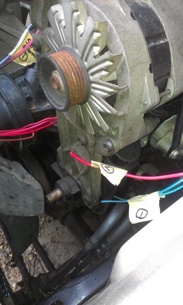
All I did last night was identify the wires that I have loose, the ones that don't have nice GM connectors on the end.

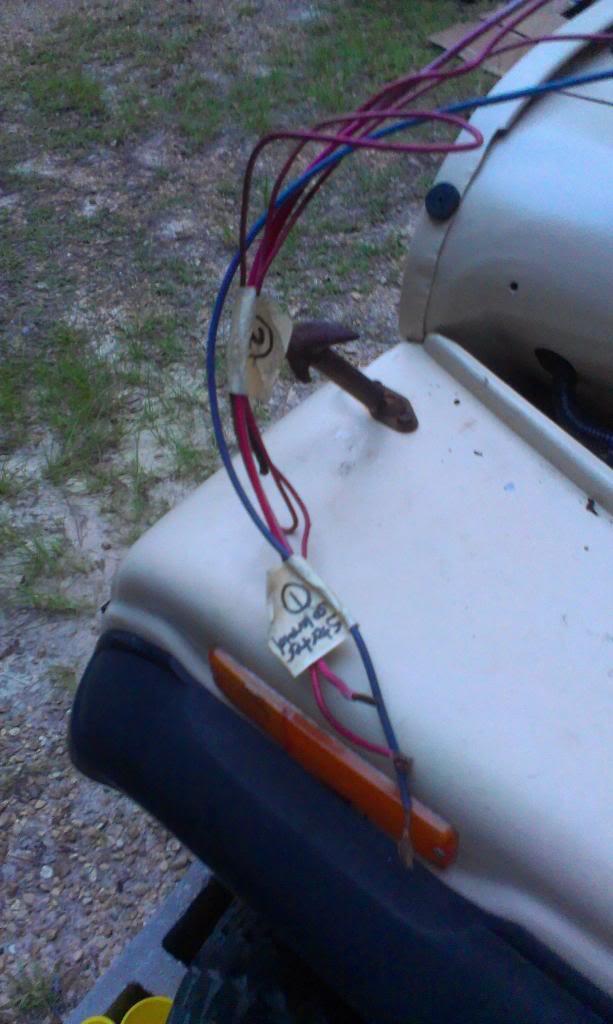
On the passenger side:

IMAG1352_zpsaa0f7601-1.jpg


From right to left: (IIRC)

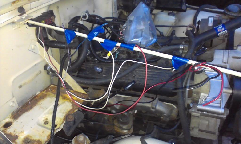
(1) red and black unmarked - my wires coming from fuel pump, power and ground
(2) white wire - can't remember, but marked
(3) red wire - TBI harness to +battery
(4) white wire - can't remember, but marked
(5) blue wire - TBI harness to knock sensor
(6) purple wire - can't remember, but marked

The above are all pretty easy, ready to be hooked up.


Inside the Jeep, from the big TBI computer:

IMAG1353_zps35b94845-1.jpg


From right to left: (IIRC)

(1) brown wire - check engine light
(2) purple wire - VSS
(3) pink wire - auxillary 12v power supply


On the TBI harness, I have a few left over connectors, BUT I think I know what they are for, and they will not be used. My TBI harness is a "stand alone" aftermarket harness made by Turbo City. It came with the Jeep. They no longer sell/deal/answer questions about this product. No big deal, I "think" I have it figured out.

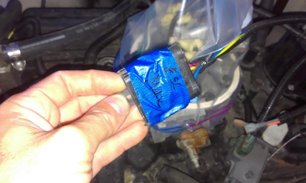
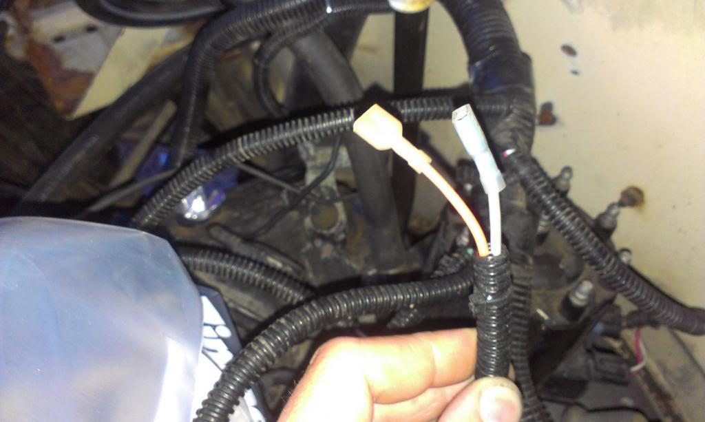
First "extra":

IMAG1355_zps318d6331-1.jpg


This plug off of the TBI harness is for the "Electronic Spark Control Module" (ESCM). This TBI harness is a "universal" harness, meaning it is made for non-TBI engines, too. This engine is a stock, GM TBI engine.

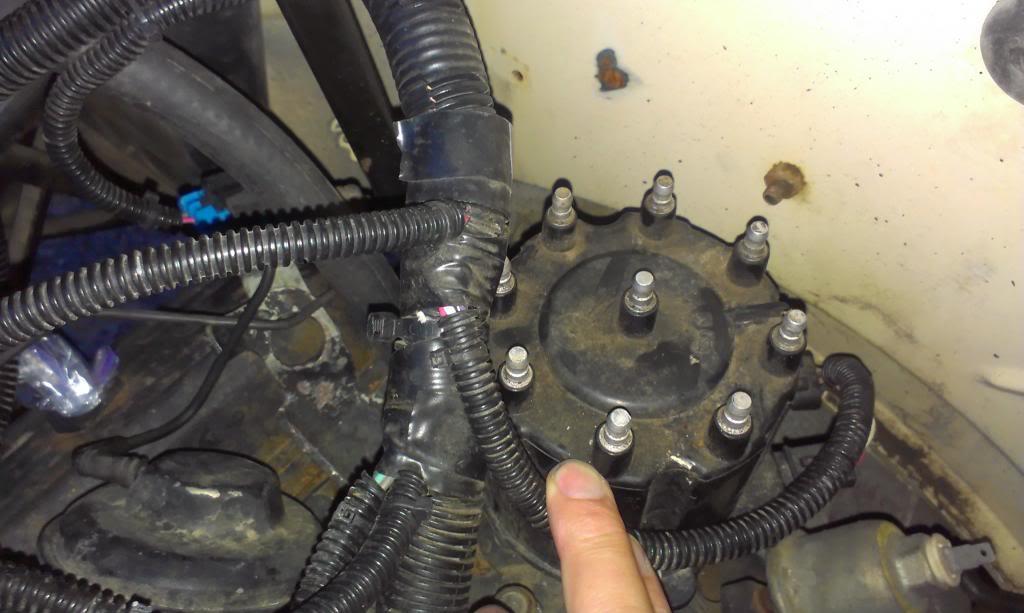
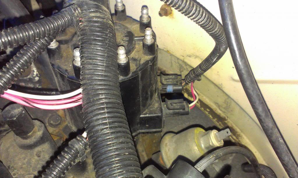
So, my distributor looks like this:

IMAG1357_zpsb33644eb-1.jpg


Note the center coil wire plug. This engine does have HEI, but it uses a separate coil.

Note the two plugs coming out the bottom of the distributor:

IMAG1356_zps4e657518-1.jpg


I believe this is where my ESCM is???? Or, is it not? Pictures I have seen of the ESCM look different then what is in the distributor. They are a little black box that plugs into the pictured harness connector. Do I need to purchase an ESCM???


The only other "unknown TBI harness wires":

IMAG1358_zps96868a1d-1.jpg


I "think" this is a another set of coil connectors?? The label fell off, and the Turbo City wiring diagram does not identify them?? I have another, similar set of coil connectors, that are marked. I plan on using the marked, coil connectors.


Quick picture of what is left of the GM engine start/charge wiring, some of it:

IMAG1359_zps2772b4a4-1.jpg


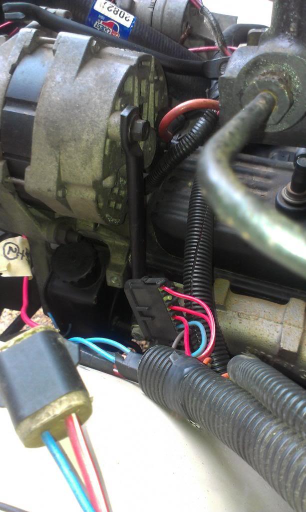
Most of this is fairly self explanatory, I think. The big positive battery cable goes to a lug on the starter. From this lug, a big wire goes to the big lug on the back of the alternator. A medium red wire comes off of this "+" starter lug and goes to the smaller post on the back of the alternator. The two extra medium red wires coming from the "+" starter lug are pictured above. One or both "might" tie into the CJ harness, for constant 12v. The blue/purple wire pictured above goes to the "start" lug on the starter. The other half needs to tie into a "12v at start only" CJ wire, to start the engine. I think this is correct.

My alternator also has a "plug" on it, with two small wires coming off of it: a "tan" wire, and a "tan/white" wire. I believe one of these is for a "charging light", not sure what the other is for??? But, can't I simplify the alternator wiring to make it a "1 wire" alternator???

Picture of what is left of the "CJ bulkhead engine wiring". I have identified most of this. Some of this needs to tie into the start wiring, and I will need a "12 volt switched" source for the TBI harness. I will also need to tie the fuse panel to a power source. Wont be too bad, I think.

IMAG1360_zpsea672d41-1.jpg


Quick picture of the GM "oil pressure switch" wiring.

IMAG1361_zps4e1f5aad-1.jpg


The Turbo City instructions mention tying some of this wiring into the "yet to be built by me" fuel pump relay circuit. Not sure if this is necessary???

 
And the last of the wires.

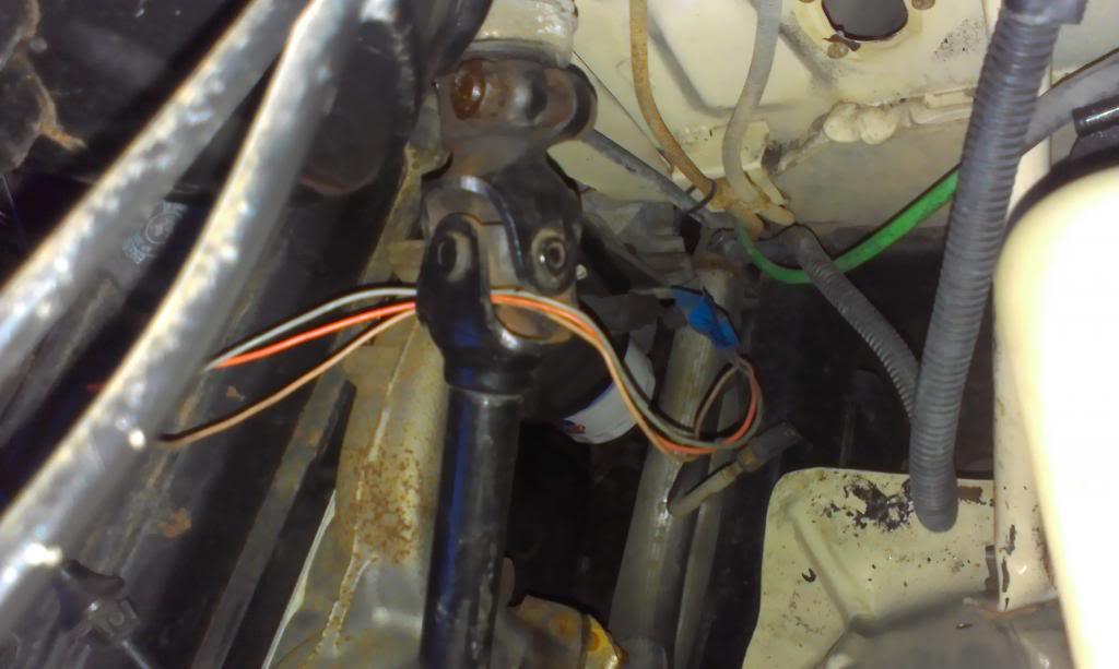
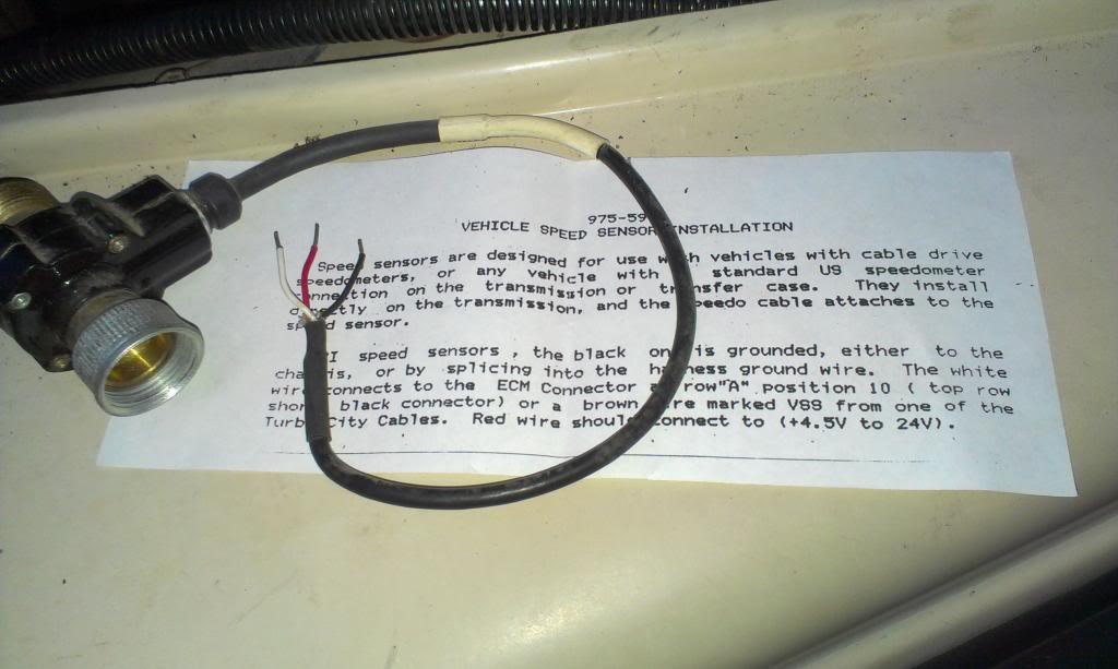
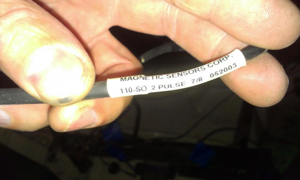
The previous owner purchased the "optional" Vehicle Speed Sensor. This needs to be wired up, too, wont be too bad.

IMAG1362_zps787ef23e-1.jpg


IMAG1364_zpsfb9442e8-1.jpg


This is a new sensor. BUT, I think it had a "short shaft" inside it that fell out, and I lost it:banghead:

So, the next few days will be some wiring, and hopefully figuring out the answers to my questions.

That's it for now:wave:
 
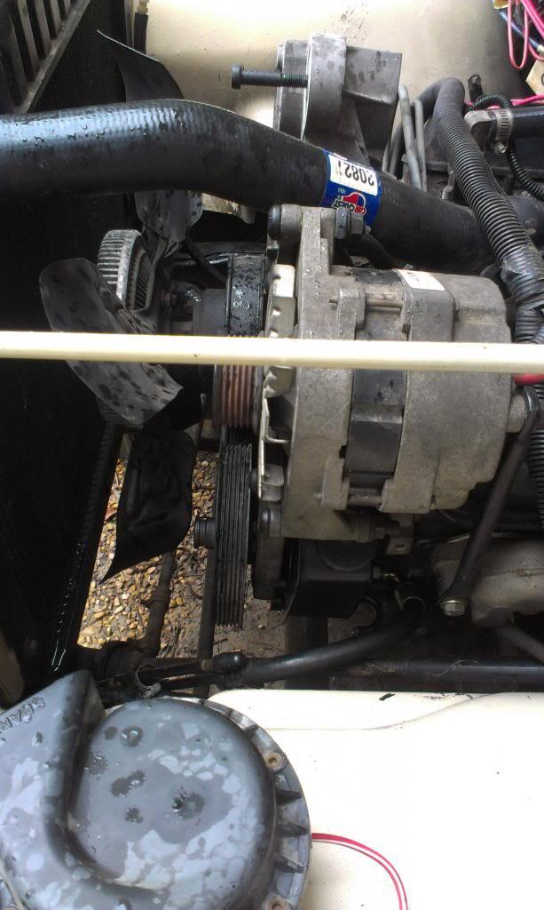
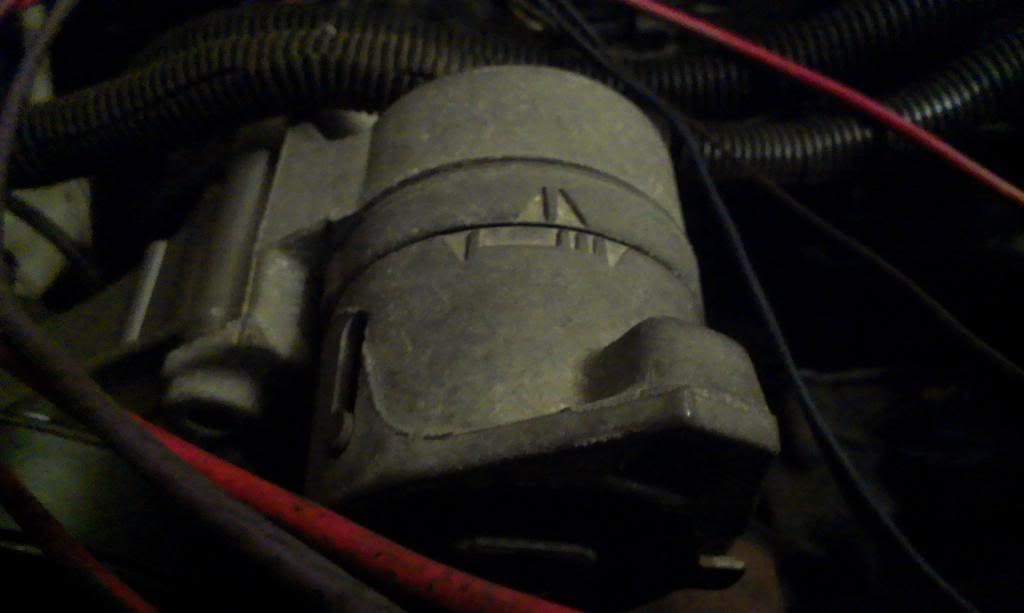
A few pictures of my alternator, I need to figure out the wiring, think I have it figured out:thumbsup:

IMAG1283_zps74daaa3211-1.jpg


IMAG1284_zps29a6924611-1.jpg


IMAG1308_zps985f5054-1.jpg


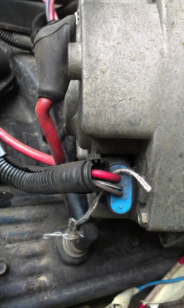
I believe it is a "CS 121/130". The below picture shows the "3 wire plug".

IMAG1307_zps586a4ae5-1.jpg


IIRC, the large red wire on this plug is going back to the "+" terminal on the starter. The other two wires are disconnected.

One of these smaller wires is for the "charge light".
One of these smaller wires is for the "excitor". I will have to read the letters to see, but this is hooked up directly to a "12v on start/run" wire, either with or without resistor, depending on the exact alternator.

That's it for now:wave:
 
Quick update, not too exciting:shrug:

A picture of how the tensioner marks line up with the AC compressor bracket marks:

IMAG1370_zpsdfd87b85-1.jpg


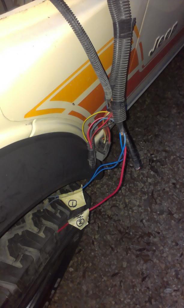
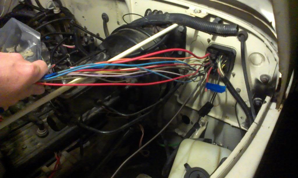
After a bunch of research, I have pretty much identified all of the bulkhead wires. The previous owner cut this harness off completely, much like what happened to the "front light" 1/2 of the bulkhead connector. I replaced the "light" harness, since I needed all of those wires. On this 1/2, I wont need all of the wires, but I will need most of them.

A picture of what I have identified:

IMAG1371_zpsb08c0a53-1.jpg


Most of these wires are what I will refer to as "chassis wiring", i.e. the following:

4wd indicator light wire ORANGE
heater motor wire LIGHT TAN
AC compressor wire (not needed at this time) DARK BROWN
temp gauge sensor wire (will use this with aftermarket gauge) VIOLET w/WHITE stripe
oil gauge sensor wire (will use this with aftermarket gauge) VIOLET
back up lights WHITE w/BLACK stripe

And a few more like that. They are not "critical" for the engine, but need to be hooked up for other stuff to work. They are all pretty easy.

Some of the larger wire (and smaller ones, too), will need to be hooked to the TBI harness, starting circuits, charging circuit, and power.

There is a "main power feed" that needs to get power RED
A wire that needs to hook up to the starter solenoid BLUE
I need to use one of these to hook up the TBI harness BLUE

And a few others. Don't "quote" me on all of these, but I am pretty sure:fingerscrossed:

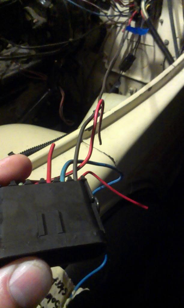
Only one wire left to identify:

IMAG1375_zps2138c2ce-1.jpg


Not sure if I need it, but I will at least identify it. It might come in handy:thumbsup:

If the rain would stop, maybe I could start hooking some of this stuff up.......

That's it for now.
 
I am with you... feel like we are in Seattle!
It has rained every day pretty much for the past 3 weeks.
Up next... heat wave... joy... NOT!

Good luck and stay dry!

cb
 
I am with you... feel like we are in Seattle!
It has rained every day pretty much for the past 3 weeks.
Up next... heat wave... joy... NOT!

Good luck and stay dry!

cb

Yep, the rain has been ridiculous:(:banghead:

I look forward to the "just hot":rotfl:


On another note, I found out I do need the "Electronic Spark Control Module", so I ordered one. It supposedly "deciphers the signal from the knock sensor" before passing the information on to the main computer:shrug:
 
Windshield washer? Horn????

Nope, those are in the other part of the harness, the part that contains all of the front light wires:thumbsup:

This little connector doo-dad sits toward the rear of the intake manifold on the 258's, I "think" it just acts as a "junction block" for wires going to other places, I will have to look at my green Scrambler to see what all it does/goes to:thumbsup::wave:
 
Back
Top