• Notice for iPhone users: DO NOT use the image size reduction option when uploading photos to the forum. This causes portrait images to post as landscape. We have added a warning to the image insert pop-up as well.

Spankrjs 1985 Spring Special CJ-7

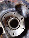
Kind of a mock up, but this is what it looks like when it is all bolted up:
20191201_133930.jpg

Ideally, if you are just swapping in bearings, and have not changed either axle shaft, you can use the same shim stack. Well, at least to get started. I switched from the original Timken bearings to SKF bearings. Now, all bearings should be the same, or pretty damn close. When I used the original shim stack, I was too tight, had to add a thin shim to get some play.

So, install your shim stack/brake backing plate "dry". Torque it down. Then, hit the end of each axle shaft (nuts on the threads to protect them) with a big hammer. This will seat both bearing races against their brake backing plates. Now, when you check "end play", you are measuring the "play" in between the bearings and their races. Too tight, the bearing will burn up. Too loose, the bearing will be damaged.

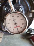
So, both side bolted down, hit each axle with a big hammer. Set up the dial indicator, driver side. Axle pushed in all the way:
20191201_140252.jpg

And then pulled outward all the way:

20191201_140259.jpg

I am at 4 thousandths, the "tight" end of the "4-8 thousandths" range. I am happy with this. New bearings, and no sealant in between all the shims/brake backing plate.

Sealant will slightly increase your "end play", especially if you use RTV or some other thick stuff. Again, I used this stuff:

20191201_145621.jpg

I put a very, very thin coat on the shims and brake backing plate. Bolted it all back together, torqued it, re-checked end play, I am close to 4.5 thousandths. I am leaving it alone.

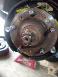
Driver side assembled, this time I remembered the dust shield. I also installed all the drum brake parts on both sides, super easy with no wheel hubs in the way!

20191201_163059.jpg

There you go, that's how you set up the bearings on the stock two piece axles. If you are really experienced, you can skip the dial indicator. I don't trust myself that much. You can feel the "play", but it is not excessive. Since the thrust block "floats" from side to side on the cross shaft, and both axles shafts are bottomed out against it, if you push the passenger side shaft in all the way, the driver side axle slides outward, and vice versa. So, I guess in a perfect world, that 4 thousandths play is split between the two bearing assemblies. You can check end play on both sides if you want, it will be the same.

Now, this setup does require that your brake backing plates are flat. I have seen them where they are bent outward, this will not work. Also, if the thrust block wears excessively, then the axles won't be "connected", and you will have too much inward "float" on each side. If all your parts are in good shape, it should work out fine.

Like I said in the opening, if any shafts/hubs would have been damaged, I would have swapped in one piece axles. Since my parts are in good shape, and this Jeep won't be thrashed, have big tires installed, or have a V8 swapped in, I should be fine :fingerscrossed:

Personally, I love my Warn full float axle kits. Instead of a single bearing on each side, you have two bearings to support the weight/load on each side, just like the front wheel hubs. It is also much easier to set the bearing end play on each wheel hub, just like the stock front wheel hubs. And, you don't need a press to install the bearings, so you can actually service the bearings. With stock two piece axles, or one piece axles, no way to repack the bearings, without destroying the outer wheel seals, and probably the bearings, too.

That's it for the bearing/axle shaft install. The next part will deal where most of the grief from this system comes from - the wheel hub to axle shaft interface.
 
Awesome write up Raymond. I have a lot of your pic-heavy "how-to's" bookmarked on my desktop.

Have you done a similar write up on installing one piece that I missed? I have stock 2 piece in my green 85 and have some one piece axles that I got in an assortment of parts that I need to install at some point.
 
  • Like
Reactions: SKT
Awesome write up Raymond. I have a lot of your pic-heavy "how-to's" bookmarked on my desktop.

Have you done a similar write up on installing one piece that I missed? I have stock 2 piece in my green 85 and have some one piece axles that I got in an assortment of parts that I need to install at some point.

Unfortunately, I don't have any pictures from when I installed any 1 Piece axle kits. It's been awhile since I have installed any.

I have only ever installed the Moser axles. Pretty easy install, the biggest issue is setting the bearing "stick out" amount. You have to install the axle bearings spacers, then slide the bearings in, check the amount of bearing "stick out". If the bearings stick out too far, you have to machine down the bearing spacer things.

On two Moser kits, IIRC, no problem with the "stick out" amount. On the Moser axles we installed in JeepAddict's white Jambo, I remember we had to machine down the spacers. His "neighbor" had a lathe and turned them down for us.

On two of the three Moser kits I installed, the differential thrust block had to be removed. I would plan on pulling the thrust block out first, just to be safe.
 
I figured I'd drive the Jeep till it had an issue and would upgrade then. The axles I got are Superior (Foote) but they're just the shafts. I'll have to buy bearings for them.
 
Finished up the rear axle hub installation this weekend.

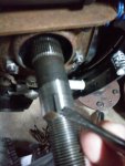
The "half moon key" I am pointing to in the below picture is important. It does not keep the hubs from spinning, BUT it does force you to reinstall the rear hub in the exact same position you removed it from. This keeps the axle "splines" in the exact same "grooves" they cut into the hubs. The only thing that keeps the hubs from spinning are the inner splines/grooves.

20191207_085218.jpg

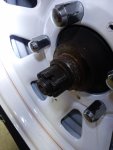
You must reattach the hub with the axle it came off of. I wrote "PS" in permanent marker on the passenger side hub to keep it straight. Again, you can see the slot in the hub where the "1/2 moon key" slides through, and the "grooves" in the hub that the axle splines cut when they were originally installed. A new hub will NOT have any splines. When you bolt a new hub on, you are actually forcing the axle splines to cut the grooves in the hubs. This is why new hub installations are a major PIA, usually involving 8' cheater pipes!!

20191207_085253.jpg

I used my electric impact, with a 1-5/16" impact socket, tightened the nut down. I used a very, very light coat of motor oil on the hub/axle interface to aid in installation. Not sure if that is necessary or prudent?

20191207_090223.jpg

I then put the brake drums on, installed the tires and wheels, lowered the vehicle to the ground. This is to keep the hubs/axles spinning when you torque the hub nut down. If you put a breaker bar or something in between the lug studs to keep the hub from turning while you torque the nut there is a good chance you will bend the hub, break your cheater bar, or break a lug stud. Kind of a PIA to do it this way, but prudent.

20191207_091755.jpg

I have an older Craftsman 1/2" drive torque wrench that goes up to 250 foot pounds.

20191207_092112.jpg

20191207_092130.jpg

To get it to "click", it was easier to use my leg/body weight to push down on the wrench. This also prevents extreme bloody knuckles if somethings slips/breaks!!

20191207_092416.jpg

From the FSM, when you reinstall an existing hub back on the axle:

20191207_093951.jpg

From the FSM, same page, new hub installation:

20191207_094011.jpg

The 250 foot pounds is just the start on a new hub installation. The 1-5/16" measurement is much more important. Even though I am reinstalling previously installed hubs, I will check this crucial measurement.

20191207_092909.jpg
 
After torquing the nuts to 250 foot pounds, the castellated nut slots did NOT align with the holes in the axle shafts. No big deal. I used my 3/4" drive ratchet, 2' cheater pipe, and slowly tightened the nuts a couple degrees at a time until the slots/holes aligned. I also kept the original nuts with the shafts they came off of, much like the hubs.

20191207_094048.jpg

I then checked the measurements on both sides, BINGO, exactly 1-5/16":

20191207_094135.jpg

I then put the Jeep back on jack stands, pulled the tires/wheels/brake drums off, and installed new cotter pins and the plastic dust shields on each axle.

20191207_132718.jpg

20191207_132903.jpg

At this point you can reinstall the drums, adjust the brakes, reinstall the tires/wheels, finished.

BUT, my rear pinion oil seal is blown out, been this way for a long while. Since the brakes are off, time to change it. More on how the brakes/pinion oil seal are related later.
 
Wondering where you got the pinstripes on your wheels done ? Local ? Couldn't find someone. The two places I got my estimates for the wheels had no one. Asked a couple other people with no luck
 
Wondering where you got the pinstripes on your wheels done ? Local ? Couldn't find someone. The two places I got my estimates for the wheels had no one. Asked a couple other people with no luck

You would have to ask JeepAddict, he had them painted :thumbsup:
 
AMC 20 Pinion Oil Seal Replacement

I am not an expert at this, I have done a few, it is still a PIA for me. Unlike a Dana 30/44, where you just torque the pinion nut to a specified number, the AMC 20 uses a "crush sleeve" between the two pinion bearings to establish the correct "pre-load" on these bearings. It is important to keep the correct pre-load on these bearings - too tight they burn up, too loose they howl/pinion will move in and out.

A smart thing to do would be to mark the pinion nut, the yoke, the pinion shaft, and the axle housing with a straight line/paint mark to keep everything perfectly aligned. If you do this, and carefully count how many turns the pinion nut takes too come off, you should be good/really close. I kind of marked the pinion nut, did not mark anything else, so I ended up having to do it the "hard way". Mark on pinion nut at 9 o-clock, "Spicer" on yoke at 3 o-clock. But, without marking the pinion shaft and housing, waste of time.

20191207_135032.jpg

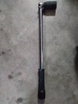
I used this style torque wrench to determine the "pre-load" on the bearings. I can't really give you a number for this, since I am measuring the resistance of the entire rear end - pinion bearings, carrier bearings, ring and pinion, and axle shafts. If you only have the pinion installed, it will be a low number. It is important to have the brake drums off, any high/low spots on the brake pads/drums will cause havoc with your reading. For reference, I was around 25 inch pounds. NOTE - it will take a little bit higher torque to get everything initially moving.

20191207_135407_HDR.jpg

From the picture above, it is a PIA to try to get an accurate reading with the axle installed under the Jeep. The exhaust/frame/ground are all in the way. I took several readings, and spun the pinion a few times, took several more. I was around 25 inch pounds rotational torque. The wrench I am using is not the best, it is in 50 inch increments. A 0 - 100 inch scale would be easier to read. From the last few Jeeps I have messed with, the rotational torque on all of them (tires and brakes removed, carrier/axles in place), was around 20-30 inch pounds.


20191207_135454_HDR.jpg

After recording the rotational torque, remove the pinion nut. You can use an impact for removal, BUT I wanted to count how many turns the pinion nut was tightened. So, you need to hold the yoke. I used a pipe wrench, not the beast, but it works. Note the cheater bar on the 1/2 drive ratchet. It takes some force to break the nut loose. I actually installed the ratchet/yoke holder, got on the side of the Jeep, stepped on the breaker pipe to break the nut loose.

20191207_140234.jpg

It took between 13-14 full turns for the nut to come off. I was able to pull the yoke off by hand. Sometimes you will have to use a two jaw puller to remove the yoke, but it is never terribly difficult to remove the yoke. Well, I haven't found one yet that was too hard, I imagine if it is rusted in place it could be a PIA.

20191207_140749.jpg

This pinion oil seal had been leaking since before JeepAddict bought this Jeep. I need to clean the bottom of the floor pans, the entire back half of the Jeep is covered in a nice gear oil/desert sand dust undercoating. I have been using the below pictured stuff to clean parts. It works great. Spray it on, it foams up, wipe the grime off. I use old tooth brushes/dish washing scouring pads to speed up the process.

20191207_143229.jpg

This yoke did not have "grooves" from the seal that would catch a finger nail, but it was still marked.

20191207_143313.jpg

About an hour and a half, started with emery cloth, then two grits of sand paper I had, then two grades of steel wool, then polish:

20191207_160544.jpg

Much better. You can still see the lines, but can not feel them. I will have to see if this seals. If not, I will have to install another yoke/pinion oil seal.

20191207_160603.jpg

The pinion oil seal I used:

20191207_160648.jpg
 
The seal that was in the rear end sat inside the pinion hole. The new seal has a flange that sits on the outer edge of the pinion hole. So, I had to clean this outer edge of the axle housing.

Before:

20191210_165833.jpg

After:

20191210_170754.jpg

And the new seal installed. This seal had a rubber outside edge, so I did not use any sealant on the OD of the seal/axle housing bore. I did greas/oil up the rubber lip of the seal.

20191210_172146.jpg

I used this sealant on the inside splines of the yoke to help prevent gear oil from creeping up the splines. I do this on axle and transfer case yokes, cheap insurance.

20191210_172153.jpg

And installed.

20191210_175521_HDR.jpg

OK, on the pinion nut, I tightened it a full 14 turns, still had pinion end play. You do not want any pinion end play (in and out movement). I chalk this up to NOT correctly marking everything before I disassembled it. No big deal, I am in the "ball park". Since there is a crush sleeve between the pinion bearings, you want to take "baby steps" tightening up this nut. The best way I can describe it, you want to "sneak up" on your rotational torque number. I tightened the nut some more until I had no pinion end play. Tighten a little, check, and repeat. Once the end play was removed, I took even smaller nut tightening steps until I achieved my previously recorded rotational torque number. This is time consuming, and aggravating, but necessary. If you exceed your rotational torque number, and put too much pre-load on the bearings, you will have to install a new "crush sleeve" and start all over again. And, it is a huge PIA to get the initial "crush" on a new crush sleeve. So, remember, baby steps. Since the pinion nut is a "self locking" style nut, it is a PIA to tighten once it is fully threaded on the pinion shaft. So, I had to use my short cheater bar on the 1/2" drive ratchet to keep tightening the nut. It will be easy to get carried away tightening this nut with the cheater bar and such, DON'T do it. A few degrees rotation at a time, baby steps. Even though it is aggravating taking all these baby steps, it would be much more aggravating to have to install a new crush sleeve and start all over again :twocents:

I eventually got my rotational torque where it was at before, so I am calling it good. If you are good/experienced at this type of work, you can do this by "feel". I am not that good/experienced, so I check the rotational torque with a wrench and match it upon reassembly.

One other rear end note - differential cover bolts. I was able to remove, without damaging, all of the Torx head bolts from the cover. BUT, I had to put a torch on each one for about 1:30 seconds to melt whatever thread locker was on them. Took awhile. Torch, remove one bolt, repeat for the 11 other bolts.

20191210_183757.jpg

That's it for now.
 
Very nice writeup. Another bookmark for me. My street Jeep has had a seeping pinion seal for years and that crush sleeve has always scared me.
 
AMC 20 Pinion Oil Seal Replacement

A smart thing to do would be to mark the pinion nut, the yoke, the pinion shaft, and the axle housing with a straight line/paint mark to keep everything perfectly aligned. If you do this, and carefully count how many turns the pinion nut takes too come off, you should be good/really close. I kind of marked the pinion nut, did not mark anything else, so I ended up having to do it the "hard way". Mark on pinion nut at 9 o-clock, "Spicer" on yoke at 3 o-clock. But, without marking the pinion shaft and housing, waste of time.

View attachment 77983

So if you were to dremel a line/mark/slot on one side of the yoke, the nut, and the pinion shaft and get all that lined up with the exact same amount of turns when reinstalling it, that should be ok, correct?
 
So if you were to dremel a line/mark/slot on one side of the yoke, the nut, and the pinion shaft and get all that lined up with the exact same amount of turns when reinstalling it, that should be ok, correct?

Theoretically, yes. Count the number of turns it takes when you remove the pinion nut.

Ideally, you should install a new pinion nut when you install a new seal, so that throws it for a loop. I reused my old pinion nut, used red lock-tite, it went on really tight, not worried about it. Do at your own risk/judgement :twocents::shrug:
 
As usual... a great write-up.

One question...
Since the pinion nut is a "self locking" style nut, it is a PIA to tighten once it is fully threaded on the pinion shaft.
I was going to ask if you used a new pinion nut, but realized marking the old one would have done absolutely nothing if you did. :o

Would following these steps and then removing the "marked pinion nut" and replacing with a new one still give the desired results?

What are some thoughts on the reuse vs. a new nut?
 
Theoretically, yes. Count the number of turns it takes when you remove the pinion nut.

Ideally, you should install a new pinion nut when you install a new seal, so that throws it for a loop. I reused my old pinion nut, used red lock-tite, it went on really tight, not worried about it. Do at your own risk/judgement :twocents::shrug:

Well, it looks like I need to type faster. :)
What are your thoughts about the use and replace?
 
Well, it looks like I need to type faster. :)
What are your thoughts about the use and replace?

These nuts are supposedly "one use only". That being said, you can reuse them once or twice, in my opinion. If they no longer go on super tight/super PIA, obviously replace it :twocents:
 
As usual... a great write-up.

One question...

I was going to ask if you used a new pinion nut, but realized marking the old one would have done absolutely nothing if you did. :o

Would following these steps and then removing the "marked pinion nut" and replacing with a new one still give the desired results?

What are some thoughts on the reuse vs. a new nut?

Even with the marking/counting turns, etc., my best advice, you still need to check it by feel/hand/wrench :twocents:

I would still mark, take note of turns, this will get you "in the ball park".

1) Slowly tighten pinion nut until there is zero end play with the pinion.
2) Once zero end play, tighten maybe 1/16 of a turn, check for resistance (wrench or hand).

With zero end play, the pinion/differential/axles will rotate very easily. Once you start to add some pre-load to the pinion bearings, you will feel the resistance. The trick, getting just enough resistance. If you go too far, new collapsible spacer :banghead:

In the past, if I had time, I would just let the local ring and pinion shop change any AMC 20 pinion yokes/seals. This guy had been building driveshafts and setting up ring and pinions for probably at least 30 years. He will do this with an impact, slowly, by hand/feel, never had problem.

A few years ago, I decided to do it myself. My first attempt did not go well. I left the brakes on, so I got a false reading, so the pinion bearings were way loose. I went for a quick drive, and it clunked bad every time I started to move. Drove home, could move the pinion in and out. Pulled the brakes, tightened the nut slowly, checked the pre-load with a wrench, no problems. I drove this Scrambler to South Dakota and back, and two Michigan trips, no problem, so pretty sure I got it right.

I have changed two or three more since then with no issues, BUT the first time is a bit intimidating. BUT, you gotta try, and sometimes fail, to figure it out.

My biggest advice:

1) Tighten up the nut SLOWLY, check repeatedly, until you remove all the end play from the pinion.
2) Once at this point, it takes just maybe a 1/4 turn at the most to get the pre-load where you want it.
3) You want to "sneak up on it", NOT exceed it
 
Pinion yoke installed, time to install the differential cover.

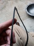
Differential cover cleaned up nicely. I decided to reuse the rubber gasket that was on it, it was working fine.

1.jpg

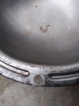
I had to pay attention to how it was installed before, you can tell the what parts of it were compressed previously:

2.jpg

The dents in the gasket line up with the parts of the diff cover that have the bolt holes:

3.jpg

I installed the rear diff cover gasket to the axle housing. I used a little bit of the Aviation Sealant stuff to help hold it in place.

The rear differential is a 3.31 Ratio, with Trac-Lock. Seems to be in good shape.

4.jpg

The only mark I could find on the ring gear, looks like a "43". IIRC, when I counted the teeth, 43 on the ring, 13 on the pinion.

5.jpg

You can see the "cut outs", behind the side gears, in the differential carrier for the clutch packs of the "Trac-Lock" . The "center pin" is also visible, it is riding on the cross shaft.

6.jpg

Marks on the pinion gear:

7.jpg

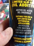
I decided to try this Limited Slip Additive, says it is good for the "Trak-Locks":

8.jpg

The Chrysler Part# is for the "Trak-Lock" differential:

9.jpg

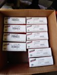
"Spicer Clause" came to town with all new U-Joints, front axles and driveshafts, and new strap kits for the driveshafts:

10.jpg
 
"Spicer Clause" also brought me a spare AMC 20 yoke, and a spare yoke that will work on the Dana 30 or Dana 300. I run the same yokes on my two Scramblers and this CJ-7. I run the Spicer straps, with Spicer bolts, I have never had a problem. I actually prefer the strap style yokes to the U-bolt style yokes.

11.jpg

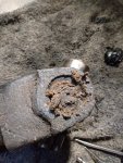
The two driveshafts that came out of this Jeep are in good shape, the u-joints are kind of crusty.

12.jpg

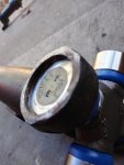
Scraping out the crud to remove the retaining clips:

13.jpg

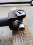
Retaining clips and grease fittings removed:

14.jpg

My two old, trusty, beat to hell u-joint sockets:

15.jpg

Driving the lower cap out:

16.jpg

Using a pair of Vice-Grips to remove the lower cap:

17.jpg

U-Joint removed from the driveshaft:

18.jpg

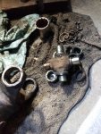
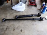
All the driveshaft u-joints out:

19.jpg


The driveshafts were really nasty. They need to be cleaned up thoroughly before installing new joints. Besides my "OCD Factor", keeping the old grit and grime out of the new joints is prudent. On the trail, you do your best. At home, I spend the extra time to clean all this crap up.

20.jpg
 
After about an hour of scrubbing, ready for new u-joints:

21.jpg

This is just a quick "Redneck Ray" U-Joint install how to. Works for me.

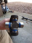
Remove the top and bottom caps, place cross in the driveshaft. gently tap in lower cap while holding the cross in place. The cross is your friend. You must use it to keep the needle bearings from falling out of place.

22.jpg

Keep tapping the lower cap in:

23.jpg

And some more until it is about like this, lower cap flush with driveshaft. At this point, tap in the upper cap, slide the cross upward, taking care to keep it engaged with the lower caps needle bearings. The trick, keeping the needles from getting knocked out of place. It is important to keep the cross engaged with both sets of needle bearings simultaneously. If not, a needle bearing can fall out, get under the cap, and crushed when you go to fully drive in the end caps. The cross is your friend, keep it engaged with the needle bearings of both caps at all times.

24.jpg

Tap both caps in until it looks like this:

25.jpg

Install a retaining clip, repeat for other side, it will look like this:

26.jpg

IF the u-joint does not turn freely, strike the driveshaft where my hammer is at a few times on both ends, that will free it up:

27.jpg

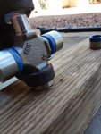
One down, three to go. Of note, make sure you insert the cross with the grease fitting pointing toward the center of the driveshaft. If you install it the other way you won't be able to grease it.

28.jpg

Two down, two to go:

29.jpg

And finished:

30.jpg
 
Back
Top