

You are using an out of date browser. It may not display this or other websites correctly.
You should upgrade or use an alternative browser.
You should upgrade or use an alternative browser.
spankrjs's Biloxi, MS '83 Scrambler
- Thread starter spankrjs
- Start date


- City
- Madison
- State
- AL
Pm me your address I have a box full of those computer harness. I'll dig though them and send you an uncut one.
That right there is what makes this forum the best Jeep forum on the planet. One post. Indisputable.

- City
- Dillsboro
- State
- IN
That right there is what makes this forum the best Jeep forum on the planet. One post. Indisputable.
Couldn't agree more!


- City
- Biloxi
- State
- MS
Pm me your address I have a box full of those computer harness. I'll dig though them and send you an uncut one.
Appreciate it, PM sent


- City
- Biloxi
- State
- MS
I received my "new to me" MCU harness from Dustin/JeeperDD yesterday, thank you again
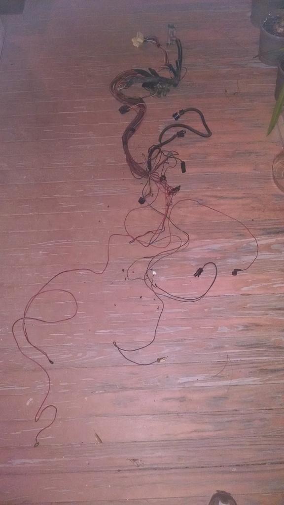
The wires toward the bottom of the picture are the ones that I need to replace in my harness. Besides the basic wires and connectors, there are a few "diode looking thingys" that are damaged on my harness, too.
I was originally planning on removing my damaged wires at the main MCU connector, and replacing them with the wires from the new MCU harness. But, the more I look at it, it might be easier just to swap out the entire harness
Even if I elect to just splice in new wires in my harness at the connector, the way this harness runs/location of the MCU, I will need to completely remove my harness from my Scrambler in order to repair it
I am leaning on just replacing the damaged wires from my harness, but not sure. If this new harness is an exact match for mine and is not damaged. might make more sense to just swap them
I need to verify they are exactly the same before proceeding.
The wires toward the bottom of the picture are the ones that I need to replace in my harness. Besides the basic wires and connectors, there are a few "diode looking thingys" that are damaged on my harness, too.
I was originally planning on removing my damaged wires at the main MCU connector, and replacing them with the wires from the new MCU harness. But, the more I look at it, it might be easier just to swap out the entire harness
Even if I elect to just splice in new wires in my harness at the connector, the way this harness runs/location of the MCU, I will need to completely remove my harness from my Scrambler in order to repair it
I am leaning on just replacing the damaged wires from my harness, but not sure. If this new harness is an exact match for mine and is not damaged. might make more sense to just swap them
I need to verify they are exactly the same before proceeding.
- City
- Biloxi
- State
- MS
Just pull it and replace the whole thing it's not that bad [emoji41]
Yep, that's what I am going to do
It would be a major PIA to start pulling and splicing the two harnesses apart and then back together 
- City
- Biloxi
- State
- MS
When I made up my mind to just swap MCU harnesses, I decided to inspect/clean/re-tape up the harness I got from Dustin.
The MCU harness has a bunch of one wire to two wire connectors, which makes sense, since most of the device wires go back to the MCU AND back to the diagnostic port.
Picture of the connections I am talking about:
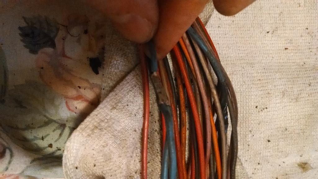
From the factory, these were wrapped up in some type of cloth tape, which after 30 years, doesn't do to good of a job:

So, besides satisfying my OCD about everything being clean, my cleaning time allowed me to inspect the whole harness for problems, and re-insulate these connectors with new electric tape.
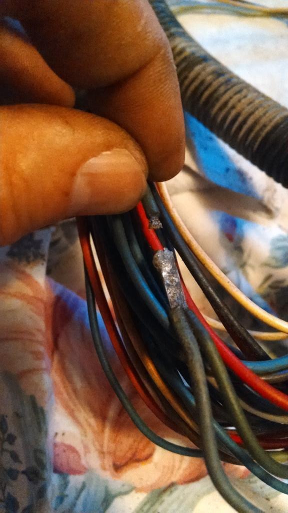
Only major problem I found: This green wire, which runs from the MCU to the Ignition control module plug, was broke off at its "two into one" connection:
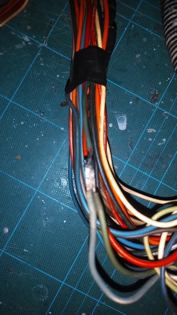
No big deal, stuck it back together with the trusty soldering iron, problem solved:
The only other damage was to the PCV solenoid plug/orange wire:
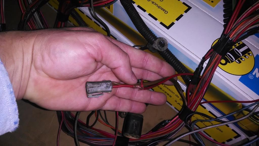
Since the PCV solenoid was supposed to be removed during a recall/TSB, I am just going to cut the connecor off and insulate the wire ends.
I also need to change the ground wire eyelet, and I might also swap out the plastic plugs on the diagnostic connector, just because mine look better
Thanks again to Dustin, his harness is 1000% better then my original butchered/burnt harness With a few quick repairs, I should have a 100% perfect MCU harness.
The time spent cleaning/inspecting this harness was time well spent When I go to hook back up all of the emissions/feed back doo-hickies, I can be confident that the wiring is correct/functional.
I plan on doing the wire harness swap on Saturday, wish me luck
Thanks again Dustin
The MCU harness has a bunch of one wire to two wire connectors, which makes sense, since most of the device wires go back to the MCU AND back to the diagnostic port.
Picture of the connections I am talking about:
From the factory, these were wrapped up in some type of cloth tape, which after 30 years, doesn't do to good of a job:
So, besides satisfying my OCD about everything being clean, my cleaning time allowed me to inspect the whole harness for problems, and re-insulate these connectors with new electric tape.
Only major problem I found: This green wire, which runs from the MCU to the Ignition control module plug, was broke off at its "two into one" connection:
No big deal, stuck it back together with the trusty soldering iron, problem solved:
The only other damage was to the PCV solenoid plug/orange wire:
Since the PCV solenoid was supposed to be removed during a recall/TSB, I am just going to cut the connecor off and insulate the wire ends.
I also need to change the ground wire eyelet, and I might also swap out the plastic plugs on the diagnostic connector, just because mine look better
Thanks again to Dustin, his harness is 1000% better then my original butchered/burnt harness
With a few quick repairs, I should have a 100% perfect MCU harness. The time spent cleaning/inspecting this harness was time well spent
When I go to hook back up all of the emissions/feed back doo-hickies, I can be confident that the wiring is correct/functional.I plan on doing the wire harness swap on Saturday, wish me luck
Thanks again Dustin
- City
- Biloxi
- State
- MS
I was able to get the MCU harnesses swapped out this weekend. The actual physical part of the work was not a problem, but I did find a wire color difference between the harnesses, more on that later.
I will let the pictures do most of the talking.
In the beginning, showing the old harness still in the engine:
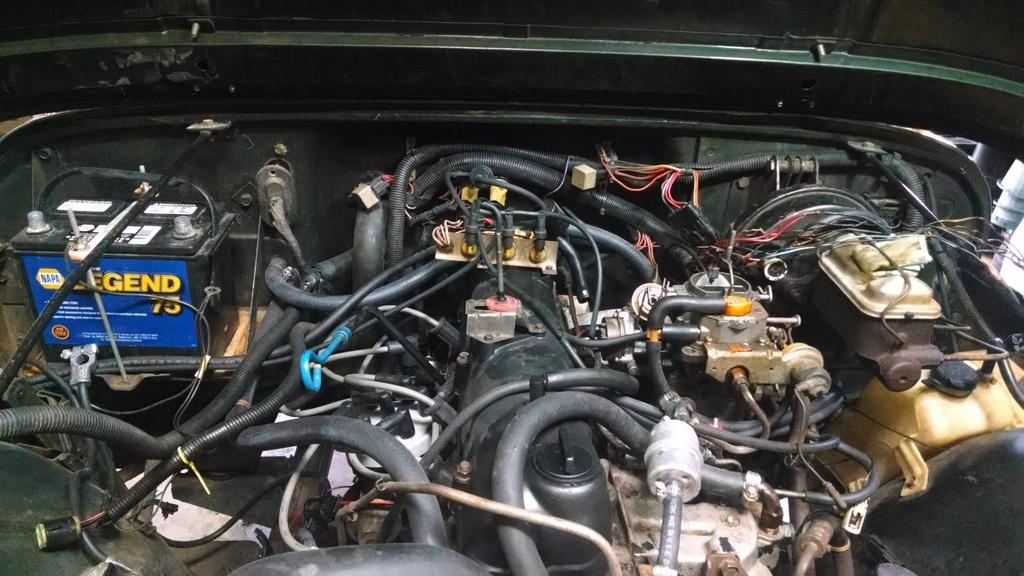
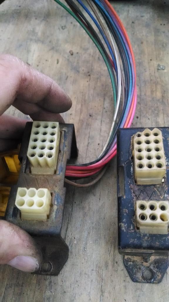
This 6 pin connector is the only place where the MCU harness connects directly to the other vehicle harness(es). You still have to disconnect all the sensors/devices, 2 different ground eyelets, unbolt the diagnostic connector, and unplug the computer under the dash. After this is done, the harness comes out easy enough. Picture of the 6 pin connector:
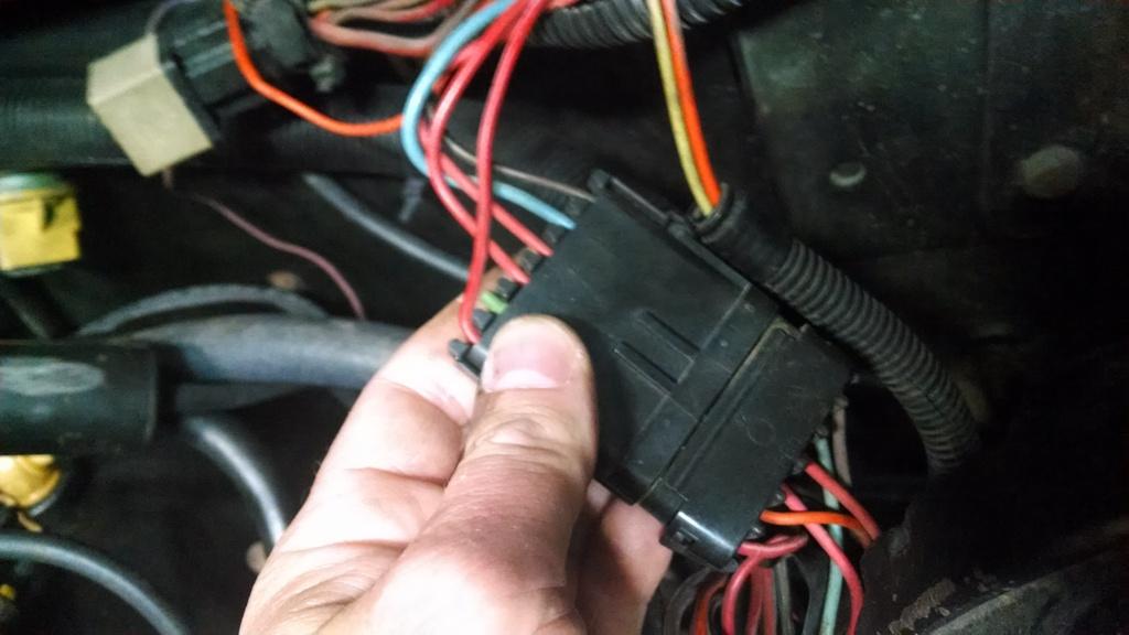
Picture I took while unplugging the MCU, while it still in place under the dash. I used a long screwdriver to gently lift the tangs that hold the plugs in place. Kind of a PIA, but not the end of the world.
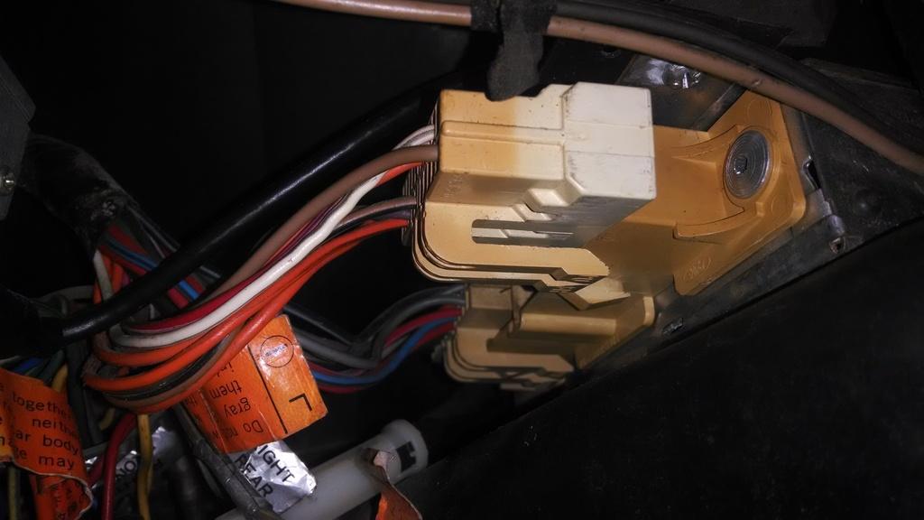
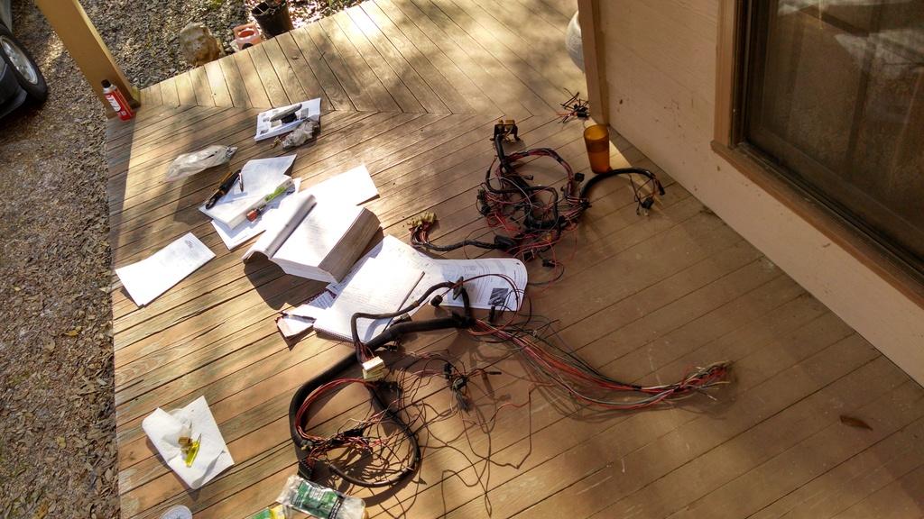
The old harness removed:
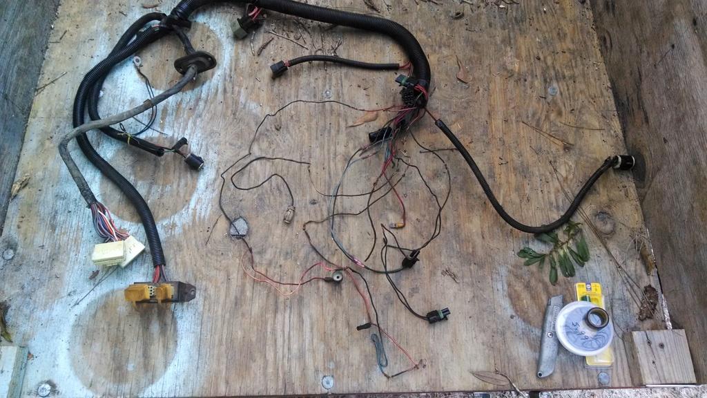
The reason for the harness swap - all the wires/connectors/diodes on the "intake manifold" portion of my harness were FUBAR:
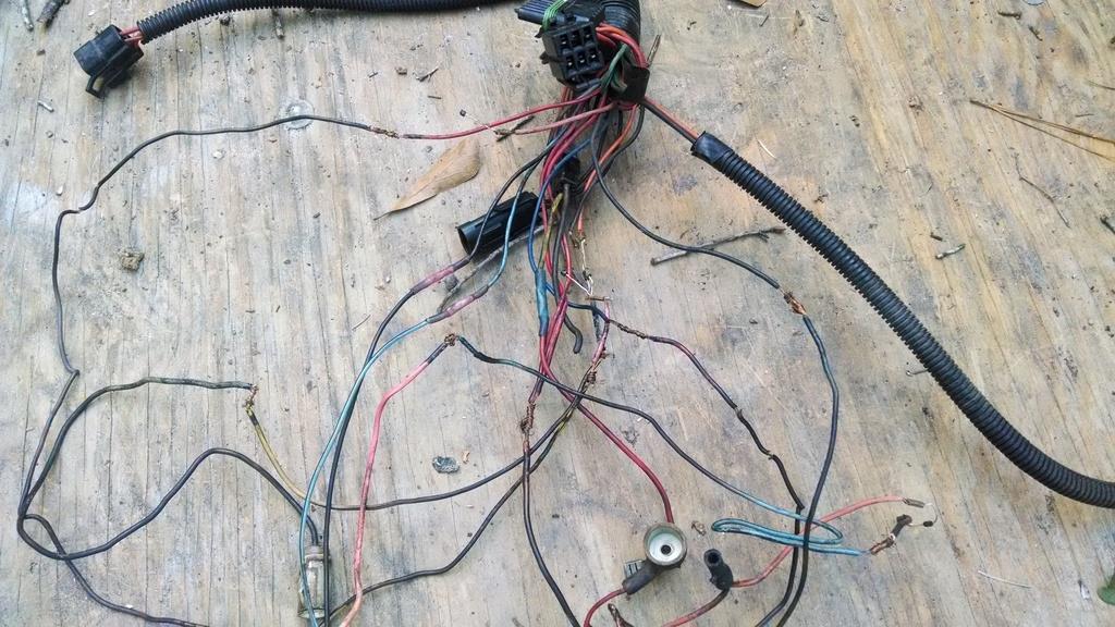
Quick under hood picture without the MCU harness, showing just the regular engine harness, no MCU harness:
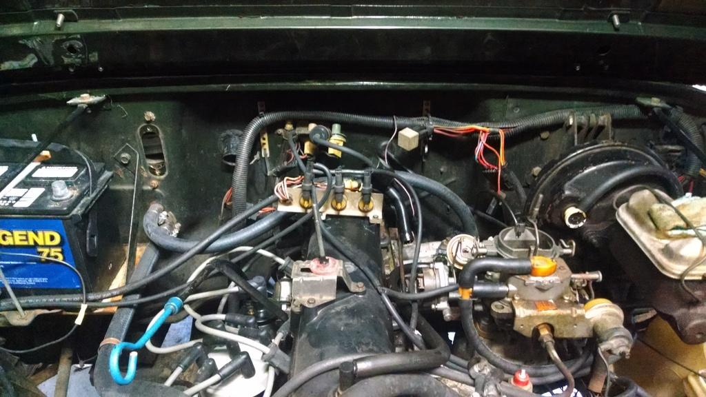
While comparing the two harnesses at the MCU connector, noticed two wires with a color difference. Not really shown here, but here is a picture anyway. Some of the wires appear different due to fading, but only two wires colors were different between the two harnesses.
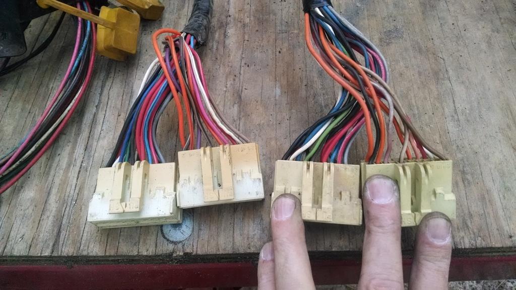
I also swapped out diagnostic port plugs/brackets for my old stuff, it was in better shape. One of the wire color changes appears here, the other wire color change shows up at the 6 PIN connector.
A lot of what I read says all the harnesses/MCU's are the same, they are not. I talked to Dustin to see if he could remember what year the harness he sent me came from, but he could not remember. I "believe" that in 1984 was when they changed to the MCU with the single/big plug. Well, at least my '84 from California had this style MCU. My green '83, which is a "49 state" model, came with the two plug MCU. Anyway, when I was comparing the two harnesses i found a difference in two wires colors:
1) The "altitude ground wire" on my old harness was black with a white stripe; the new harness had a blue wire for this purpose.
2) The "start" signal at the 6 pin connector was blue on my old harness, white on the new harness. The previous picture of my 6 pin connector shows this blue wire in that port, and it matches up with a blue wire on my chassis harness.
After finding these two differences, research time!!!!!!!!!!
So, after comparing each PIN at the MCU connector, and all the PINs at the diagnostic connector, plus the PINs at the 6 PIN connector, and the harness to device plug wires/colors, this is what I found:
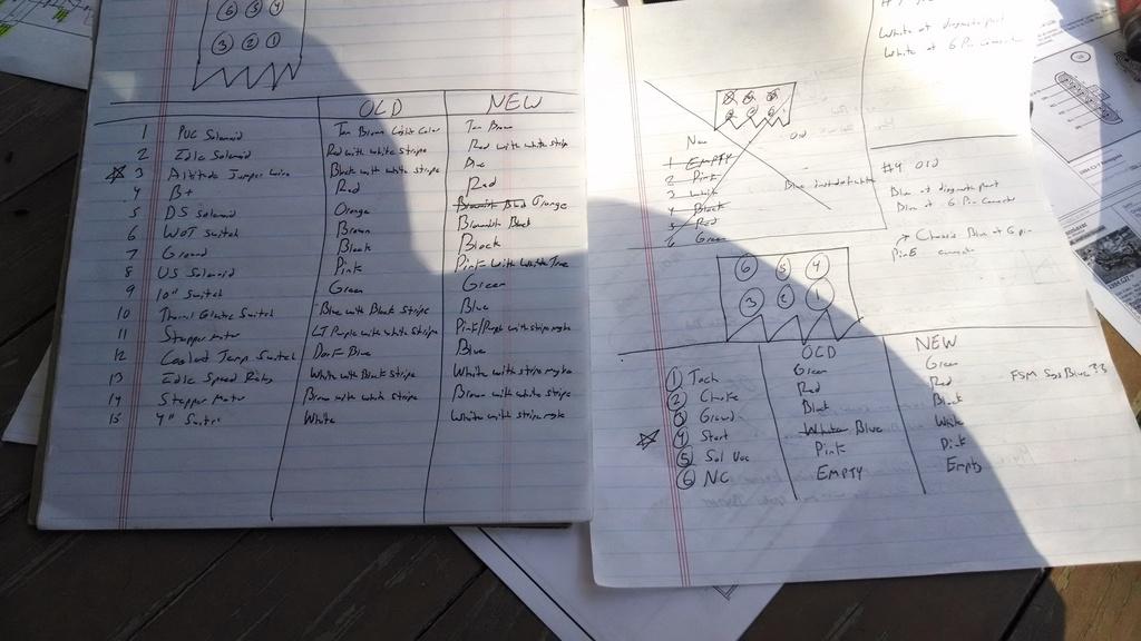
Basically, the harness are 100% the same except for the color of the following two wires:
1) Altitude Jumper Wire (black/white on old, blue on new)
2) Start signal wire at 6 PIN connector (blue on old, white on new)
Another interesting note: my 82 FSM says the choke check wire at the diagnostic port should be blue; both of my harnesses use red wires, which makes sense, since the choke hot wire is red.
All of the "research" checking took about 4 hours, but I can sleep soundly now!!!!!!!!
I will let the pictures do most of the talking.
In the beginning, showing the old harness still in the engine:
This 6 pin connector is the only place where the MCU harness connects directly to the other vehicle harness(es). You still have to disconnect all the sensors/devices, 2 different ground eyelets, unbolt the diagnostic connector, and unplug the computer under the dash. After this is done, the harness comes out easy enough. Picture of the 6 pin connector:
Picture I took while unplugging the MCU, while it still in place under the dash. I used a long screwdriver to gently lift the tangs that hold the plugs in place. Kind of a PIA, but not the end of the world.
The old harness removed:
The reason for the harness swap - all the wires/connectors/diodes on the "intake manifold" portion of my harness were FUBAR:
Quick under hood picture without the MCU harness, showing just the regular engine harness, no MCU harness:
While comparing the two harnesses at the MCU connector, noticed two wires with a color difference. Not really shown here, but here is a picture anyway. Some of the wires appear different due to fading, but only two wires colors were different between the two harnesses.
I also swapped out diagnostic port plugs/brackets for my old stuff, it was in better shape. One of the wire color changes appears here, the other wire color change shows up at the 6 PIN connector.
A lot of what I read says all the harnesses/MCU's are the same, they are not. I talked to Dustin to see if he could remember what year the harness he sent me came from, but he could not remember. I "believe" that in 1984 was when they changed to the MCU with the single/big plug. Well, at least my '84 from California had this style MCU. My green '83, which is a "49 state" model, came with the two plug MCU. Anyway, when I was comparing the two harnesses i found a difference in two wires colors:
1) The "altitude ground wire" on my old harness was black with a white stripe; the new harness had a blue wire for this purpose.
2) The "start" signal at the 6 pin connector was blue on my old harness, white on the new harness. The previous picture of my 6 pin connector shows this blue wire in that port, and it matches up with a blue wire on my chassis harness.
After finding these two differences, research time!!!!!!!!!!
So, after comparing each PIN at the MCU connector, and all the PINs at the diagnostic connector, plus the PINs at the 6 PIN connector, and the harness to device plug wires/colors, this is what I found:
Basically, the harness are 100% the same except for the color of the following two wires:
1) Altitude Jumper Wire (black/white on old, blue on new)
2) Start signal wire at 6 PIN connector (blue on old, white on new)
Another interesting note: my 82 FSM says the choke check wire at the diagnostic port should be blue; both of my harnesses use red wires, which makes sense, since the choke hot wire is red.
All of the "research" checking took about 4 hours, but I can sleep soundly now!!!!!!!!
- City
- Biloxi
- State
- MS
After all the research, plus a few connector swaps, I installed the new to me harness:
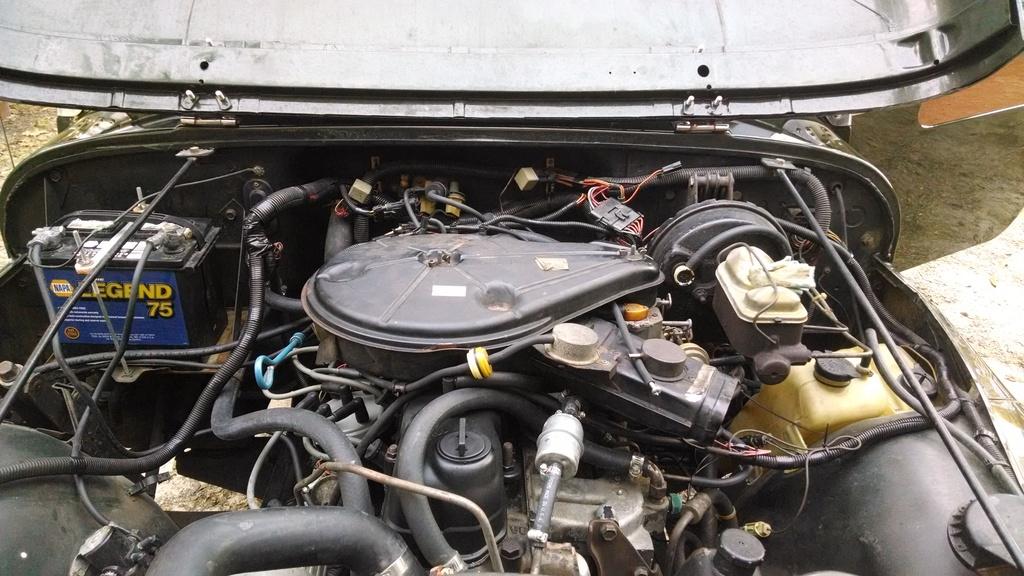
The part of my original harness that was damaged sat on top of the intake/exhaust, sandwiched between the valve cover and the carb. The "new to me" harness had enough length, so I ran it over the PB booster bracket, tied it to the head light harness, then ran the wires to the intake/carb sensors. This keeps them away from all the engine heat, should help preserve them. Not the best picture, but you can see what I mean:
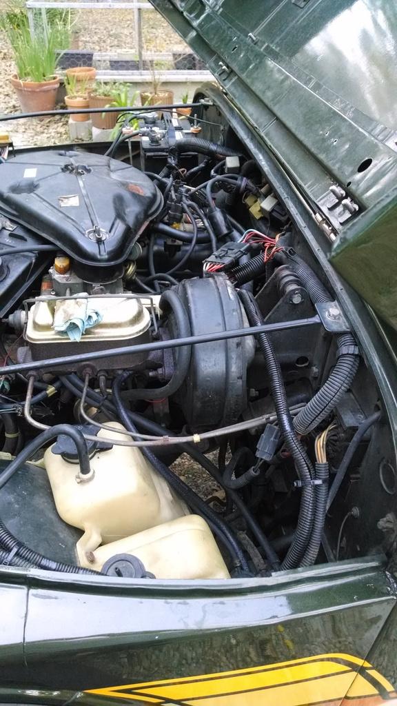
So, after all that work, I am confident that I have a good MCU harness. But, the SolVac still doesn't work
 Next step, check the electric plug for power, check the vacuum solenoid on the valve cover.
Another thing I "realized": When trying to "restore" all this crap, don't just rely on the FSM or the internet. Not everything you read/see will be correct for your vehicle
With that in mind, I am relying on my original under hood sticker for direction, probably the safest bet:
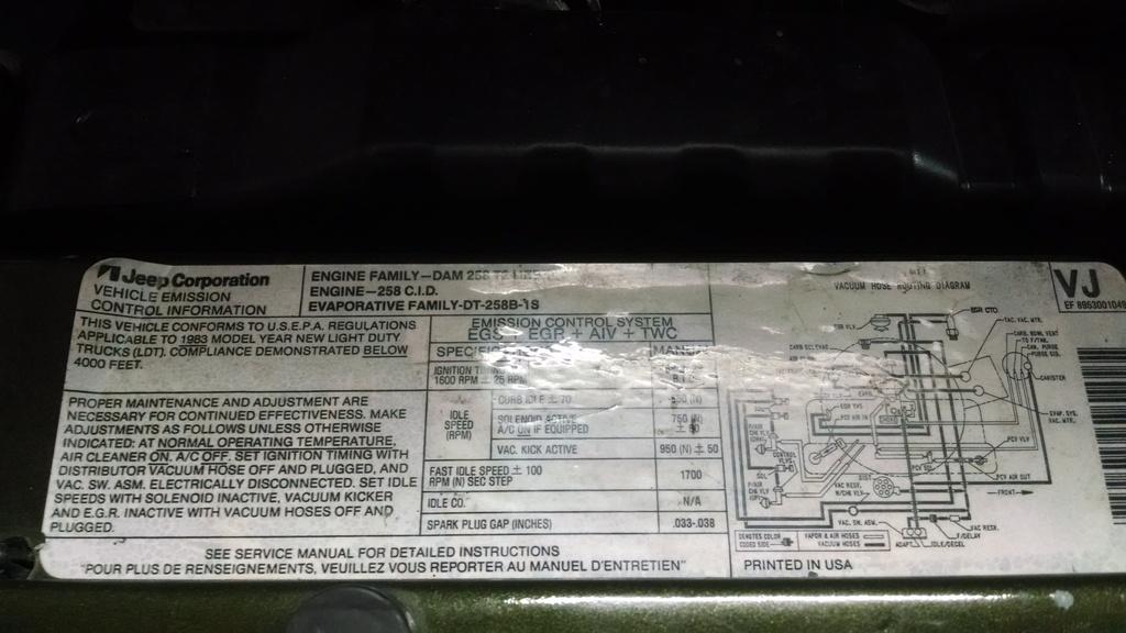
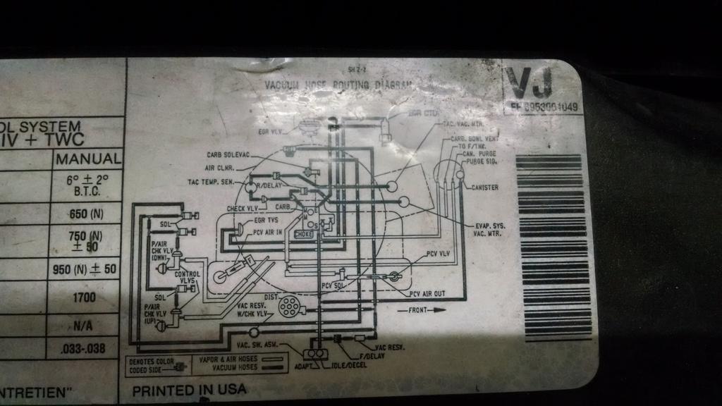
My game plan:
1) Get the SolVac working
2) Get the air cleaner outer trap door working (inner works fine now)
3) Hook up the EGR
4) Install all the pulse air stuff
That's it for now
The part of my original harness that was damaged sat on top of the intake/exhaust, sandwiched between the valve cover and the carb. The "new to me" harness had enough length, so I ran it over the PB booster bracket, tied it to the head light harness, then ran the wires to the intake/carb sensors. This keeps them away from all the engine heat, should help preserve them. Not the best picture, but you can see what I mean:
So, after all that work, I am confident that I have a good MCU harness. But, the SolVac still doesn't work
Next step, check the electric plug for power, check the vacuum solenoid on the valve cover.Another thing I "realized": When trying to "restore" all this crap, don't just rely on the FSM or the internet. Not everything you read/see will be correct for your vehicle
With that in mind, I am relying on my original under hood sticker for direction, probably the safest bet:
My game plan:
1) Get the SolVac working
2) Get the air cleaner outer trap door working (inner works fine now)
3) Hook up the EGR
4) Install all the pulse air stuff
That's it for now

- City
- Biloxi
- State
- MS
You are a braver man than me. I hate wiring and you went all in there. Props
Appreciate it
But, that is only one piece of the puzzle, I still need to verify all the doo-hicky's are working like they should, and fit the missing pieces
This is a bit more mentally challenging work compared to what I have been used to doing
- City
- Biloxi
- State
- MS
I have been working on my "feedback system restoration" the last few nights after work. I spend quite a bit of time reading the FSM, and more importantly, the Diagnostic flow charts located in the '83 supplement portion of my manual. I am trying to wrap my mind around all this stuff. The more I learn about it, the more I appreciate this system. After installing TBI and MPI systems on CJ's, I kind of like this "pre-fuel injection" complete engine management system. Also, this being a '83, it is the first year for "49 state" CJ's to have the "MCU/feedback" system. I figure if I can "master" my '83's system, then later year CJ's should be similar, with just a few more doo-hickies added here and there The information/understanding/hopefully some diagnostic reasoning developed on my '83's restoration will help me in the near future 
So, with my "new" MCU harness installed, I started to diagnose why my SolVac is not working. First, I went through the SolVac relay test, to try to determine why I did not have power to the SolVac after start up. Sure enough, went through the checks, MCU sending voltage to the relay, just no voltage out of the relay. So, swapped in a new relay, and I now have power present at the SolVac connector for approximately one minute after start up, then the power is cut by the MCU. To go further, now when I turn on the headlights, I get the voltage signal to the SolVac connector, too. Turn off the headlights, the MCU kills power to the SolVac. I don't have AC, so I can't check if the SolVac energizing wire gets voltage when the compressor engages, but I am confident that it would work, too.
With the electrical engagement side of the SolVac tested, and now working, well, at least the harness portion, the SolVac is still non-operational, I went on to test the vacuum portion. The MCU should energize the SolVac Switching Solenoid for approximately 15 seconds after start up. Manifold vacuum should flow from the intake manifold, through the vacuum canister located under the battery tray, to the three vacuum switching solenoids located on top of the manifold. The switching solenoid for the SolVac is the solenoid farthest from the manifold vaccuum source connection; the one all the way on the driver side. First, I checked for vacuum at the SolVac after start up. Very little vacuum, maybe 2", showing. But, it did have some, and it did drop to zero after approximately 15 seconds. Next, I checked the electrical portion of the switching solenoid. It is getting energized by the MCU for approximately 15 seconds after start up, so that is good. Next, I checked vacuum coming out of the SolVac switching solenoid. Same thing, like 2", not manifold vacuum like it should be. So, I checked for manifold vacuum where the vacuum line enters the three switching solenoid assembly, and sure enough, 18" of vacuum.
So, the electrical portion of the switch works, I am getting 18" of vacuum at the solenoid trio, why am I not getting manifold vacuum through the Solvac switching solenoid? Well, after looking/thinking about it, it became obvious: vacuum enters the solenoid trio at the far end of the solenoid trio; it must flow past the two Pulse Air solenoids before it gets to the SolVac switching solenoid; I left both of my Pulse Air switching solenoids not hooked up/plugged: vaccuum was escaping out of their open ports!!!!!!!!!! I guess they open up on start up, too: will have to verify.
So, I plugged up the two Pulse Air solenoids, started the Scrambler up, sure enough, 18" of manifold vacuum at the SolVac connector for around 15 seconds, then the vacuum is cut off, like it should.
So, after all that, I now have the harness/vacuum portion of the SolVac system working. But, my exisitng SolVac is dead. But, I have a new one to swap on, so I should be able to get this portion of the feedback system working.
I guess my point from this long rambling post - You can't just swap parts, you need to diagnose/verify the problem I knew my SolVac was shot, but if I would have just swapped in a new one, it still would not have worked, due to the vacuum leak at the solenoid trio.
Also, all this reading/diagnosing/testing is helping me to better understand how this system works. Not just the SolVac portion, but the entire "feedback system". No one part really works by itself, especially on the vacuum parts.
As for the SolVac, as far as I can tell, all it does is idle the engine up slightly in two "steps": the vacuum portion holds the idle at 1100 RPM, the electric portion will hold it at 900. Both of these RPM settings are adjustable.
Upon start up/re-start, vacuum locks the SolVac arm in place, holding a fast 1,100 RPM idle for 15 seconds. After 15 seconds, vacuum is cut off, SolVac arm slides inward. But, the electrical portion stops the arm from sliding in all the way, it holds it at the 900 RPM stop point for about 45 seconds. After 45 seconds, electrical current is cut, the arm slides all the way in, you are now idling at your 680 RPM base idle.
The electrical portion comes into play on a CJ in two ways: AC is turned on, headlight are turned on. The MCU knows when the AC is cut on from the brown wire coming off the compressor, which passes through the 6 PIN connector. As for the headlights, I "assume" one of the wires from the 6 pin connector, that ties the MCU harness to the regular under hood/chassis harness (guessing Red wire, PIN D, "IGN lPS fuse"), lets the MCU know the lights are on. Regardless, when either/both conditions are met, the MCU energizes the SolVac to kick up the idle to 900 RPM to compensate for the additional load on the engine.
Now, how the SolVac itself functions confused me a bit, until I started playing with the new one. The arm naturally stays all the way out. But, if you push on it, it slides back in. Release it, it slides back out. But, once you apply vaccum to the SolVac, vacuum locks the arm in the all the way extended position. You can't push it back in until vacuum is released. The electrical portion will not force the arm out. But, if it is energized, and you open the throttle releasing pressure off the SolVac arm, it will lock in place on the second 900RPM fast idle step.
Once I install the new SoVac, I will have to adjust the two SolVac idle RPM settings. The vacuum RPM portion is adjusted via an adjusting screw located on the carb throttle lever. The electrical portion is adjusted via the SolVac arm itself.
I will probably go ahead and reset/check all four idle settings while I am at it:
1) Choke fast idle on second step -1,700RPM
2) SolVac vacuum idle - 1,100RPM
3) SolVac electric idle - 900RPM
4) curb idle - 680RPM
As for the purpose of the SolVac, I kind of get it. I understand the electrical portion kicking in to raise the idle when a load is placed on the engine; either the AC clutch engaging or the alternator getting put under load from the headlights being turned on. The curb idle drops under these conditions, so I understand the idea of "kicking up the idle a hair". The 4.0 in my LJ does this when you turn the AC on, via its computer. The other part, upon restart, kind of makes sense: Not cold enough for the choke to engage the fast idle, the carb is a bit grumpy at first at a low curb idle of 680 RPM. So, kick it up to 1,100 RPM for 15 seconds, then to 900RPM for 45 seconds, then base idle, helps smooth everything out. I am sure this temporary fast idle also helps emissions in some way, too. Maybe helps warm the cat up faster or something, or helps to more completely burn the mixture under this slightly rich start up closed loop mixture setting???
Another thing I am curious about: I only checked for SolVac operation on a "hot restart". I wonder if it is energized during cold start up? Not that it would matter, the 1,700 RPM fast choke idle is beyond the SolVac arm reach anyway. I am just interested in knowing if maybe the SolVac is only operational on a hot restart, mainly just out of curiosity
Anyway, before setting/checking the idle RPM settings, I need to swap in a new choke. My existing bi-metal spring does not have enough tension left to fully shut the choke. If I twist the choke housing tighter to fully close the choke on start up, it will never fully open. But, choke swap is easy.
After the choke swap, I will install the new SolVac and get it set up. Then, try to get my TAC thermal door functioning on the air cleaner, then the EGR system (have to install a new intake to exhaust tube), and then the Pulse Air system. At least my vapor canister/PVC system are intact/functional, but I might swap in a new charcoal canister anyway
That's it for now
The information/understanding/hopefully some diagnostic reasoning developed on my '83's restoration will help me in the near future So, with my "new" MCU harness installed, I started to diagnose why my SolVac is not working. First, I went through the SolVac relay test, to try to determine why I did not have power to the SolVac after start up. Sure enough, went through the checks, MCU sending voltage to the relay, just no voltage out of the relay. So, swapped in a new relay, and I now have power present at the SolVac connector for approximately one minute after start up, then the power is cut by the MCU. To go further, now when I turn on the headlights, I get the voltage signal to the SolVac connector, too. Turn off the headlights, the MCU kills power to the SolVac. I don't have AC, so I can't check if the SolVac energizing wire gets voltage when the compressor engages, but I am confident that it would work, too.
With the electrical engagement side of the SolVac tested, and now working, well, at least the harness portion, the SolVac is still non-operational, I went on to test the vacuum portion. The MCU should energize the SolVac Switching Solenoid for approximately 15 seconds after start up. Manifold vacuum should flow from the intake manifold, through the vacuum canister located under the battery tray, to the three vacuum switching solenoids located on top of the manifold. The switching solenoid for the SolVac is the solenoid farthest from the manifold vaccuum source connection; the one all the way on the driver side. First, I checked for vacuum at the SolVac after start up. Very little vacuum, maybe 2", showing. But, it did have some, and it did drop to zero after approximately 15 seconds. Next, I checked the electrical portion of the switching solenoid. It is getting energized by the MCU for approximately 15 seconds after start up, so that is good. Next, I checked vacuum coming out of the SolVac switching solenoid. Same thing, like 2", not manifold vacuum like it should be. So, I checked for manifold vacuum where the vacuum line enters the three switching solenoid assembly, and sure enough, 18" of vacuum.
So, the electrical portion of the switch works, I am getting 18" of vacuum at the solenoid trio, why am I not getting manifold vacuum through the Solvac switching solenoid? Well, after looking/thinking about it, it became obvious: vacuum enters the solenoid trio at the far end of the solenoid trio; it must flow past the two Pulse Air solenoids before it gets to the SolVac switching solenoid; I left both of my Pulse Air switching solenoids not hooked up/plugged: vaccuum was escaping out of their open ports!!!!!!!!!! I guess they open up on start up, too: will have to verify.
So, I plugged up the two Pulse Air solenoids, started the Scrambler up, sure enough, 18" of manifold vacuum at the SolVac connector for around 15 seconds, then the vacuum is cut off, like it should.
So, after all that, I now have the harness/vacuum portion of the SolVac system working. But, my exisitng SolVac is dead. But, I have a new one to swap on, so I should be able to get this portion of the feedback system working.
I guess my point from this long rambling post - You can't just swap parts, you need to diagnose/verify the problem
I knew my SolVac was shot, but if I would have just swapped in a new one, it still would not have worked, due to the vacuum leak at the solenoid trio.Also, all this reading/diagnosing/testing is helping me to better understand how this system works. Not just the SolVac portion, but the entire "feedback system". No one part really works by itself, especially on the vacuum parts.
As for the SolVac, as far as I can tell, all it does is idle the engine up slightly in two "steps": the vacuum portion holds the idle at 1100 RPM, the electric portion will hold it at 900. Both of these RPM settings are adjustable.
Upon start up/re-start, vacuum locks the SolVac arm in place, holding a fast 1,100 RPM idle for 15 seconds. After 15 seconds, vacuum is cut off, SolVac arm slides inward. But, the electrical portion stops the arm from sliding in all the way, it holds it at the 900 RPM stop point for about 45 seconds. After 45 seconds, electrical current is cut, the arm slides all the way in, you are now idling at your 680 RPM base idle.
The electrical portion comes into play on a CJ in two ways: AC is turned on, headlight are turned on. The MCU knows when the AC is cut on from the brown wire coming off the compressor, which passes through the 6 PIN connector. As for the headlights, I "assume" one of the wires from the 6 pin connector, that ties the MCU harness to the regular under hood/chassis harness (guessing Red wire, PIN D, "IGN lPS fuse"), lets the MCU know the lights are on. Regardless, when either/both conditions are met, the MCU energizes the SolVac to kick up the idle to 900 RPM to compensate for the additional load on the engine.
Now, how the SolVac itself functions confused me a bit, until I started playing with the new one. The arm naturally stays all the way out. But, if you push on it, it slides back in. Release it, it slides back out. But, once you apply vaccum to the SolVac, vacuum locks the arm in the all the way extended position. You can't push it back in until vacuum is released. The electrical portion will not force the arm out. But, if it is energized, and you open the throttle releasing pressure off the SolVac arm, it will lock in place on the second 900RPM fast idle step.
Once I install the new SoVac, I will have to adjust the two SolVac idle RPM settings. The vacuum RPM portion is adjusted via an adjusting screw located on the carb throttle lever. The electrical portion is adjusted via the SolVac arm itself.
I will probably go ahead and reset/check all four idle settings while I am at it:
1) Choke fast idle on second step -1,700RPM
2) SolVac vacuum idle - 1,100RPM
3) SolVac electric idle - 900RPM
4) curb idle - 680RPM
As for the purpose of the SolVac, I kind of get it. I understand the electrical portion kicking in to raise the idle when a load is placed on the engine; either the AC clutch engaging or the alternator getting put under load from the headlights being turned on. The curb idle drops under these conditions, so I understand the idea of "kicking up the idle a hair". The 4.0 in my LJ does this when you turn the AC on, via its computer. The other part, upon restart, kind of makes sense: Not cold enough for the choke to engage the fast idle, the carb is a bit grumpy at first at a low curb idle of 680 RPM. So, kick it up to 1,100 RPM for 15 seconds, then to 900RPM for 45 seconds, then base idle, helps smooth everything out. I am sure this temporary fast idle also helps emissions in some way, too. Maybe helps warm the cat up faster or something, or helps to more completely burn the mixture under this slightly rich start up closed loop mixture setting???
Another thing I am curious about: I only checked for SolVac operation on a "hot restart". I wonder if it is energized during cold start up? Not that it would matter, the 1,700 RPM fast choke idle is beyond the SolVac arm reach anyway. I am just interested in knowing if maybe the SolVac is only operational on a hot restart, mainly just out of curiosity
Anyway, before setting/checking the idle RPM settings, I need to swap in a new choke. My existing bi-metal spring does not have enough tension left to fully shut the choke. If I twist the choke housing tighter to fully close the choke on start up, it will never fully open. But, choke swap is easy.
After the choke swap, I will install the new SolVac and get it set up. Then, try to get my TAC thermal door functioning on the air cleaner, then the EGR system (have to install a new intake to exhaust tube), and then the Pulse Air system. At least my vapor canister/PVC system are intact/functional, but I might swap in a new charcoal canister anyway
That's it for now


- City
- Biloxi
- State
- MS
That's it? Really?
I haven't written that much since grad school....and that's been a long time.
LOL
Piece of cake. LOL
Actually, not any harder then a fuel injection system wiring harness, pretty similar actually, except all the vacuum doo-dads
You are amazing Raymond. great write up.
Appreciate it, but I wouldnt go that far
- City
- Biloxi
- State
- MS
I did a few quick/easy under hood chores last night.
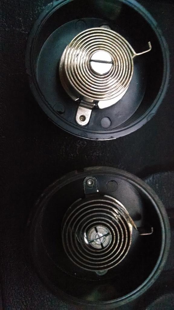
I changed out the old choke, the internal spring was weak, would not close the choke.
New on top, old on bottom. The new ones metal coil thing is much "springier", works great.
With a fully functional choke again, the cold starts are much easier.
I was missing the "check valve", Jeep Part #J3228426, on the vacuum line going to the outer trap door in my air cleaner. I obtained a new one, from Crown, and installed it. I have not found anything yet on which way to install it. It is a black/white valve. Anyway, I plugged it in one way, it just allowed vacuum to go right through it and shut the outer door. I installed it the other way, and now the door stays open. I am going to hook this valve up to a vacuum gauge/vacuum source and try to figure out what it is supposed to do. I have not found much information on it A big problem I have right now - our temperatures are staying over 60 degrees, so the outer door should be staying open, which it is now, but I am not 100% sure I actually "fixed the problem" by just sticking this part in.
The other part of the outer trap door system, the thermal vacuum switch. Mine looks like this, which is different from all the other ones I have seen:
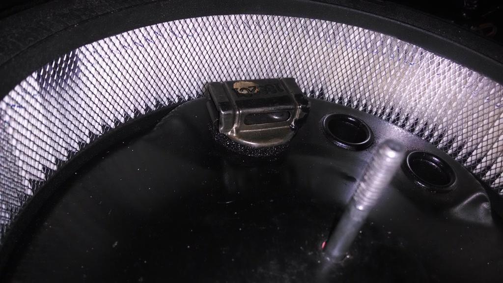
References to this switch seem to indicate one of these:
http://www.pt374.www.auto-parts-onl...eaner-temperature-sensor-jeep-cj7-ats-17.html
I ordered one of the above switches to install. Mine appears to be working, but it is annoying. Manifold vacuum flows into one port on the bottom of this switch. It flows out the other port to the outer air cleaner vacuum motor depending on temperature. I "assume" that if the temperature is high enough, manifold vacuum is diverted inside the air cleaner, not 100% sure. The outer door is a bit confusing to me. The inner door is simple - manifold vacuum opens it. The outer door, manifold vacuum pulls it to the heat mode, so I assume once it warms up, manifold vacuum should be shut off to this door, allowing it to fall toward the bottom of the snorkel and let it in cool air. That's how it should work.
My existng thermal vacuum switch has this little metal flap on the air cleaner side. It constantly vibrates when the engine is running, making an annoying "buzzing sound". The sound is loud enough to hear with the hood shut, over the idling engine. This picture better shows the metal flap thing:
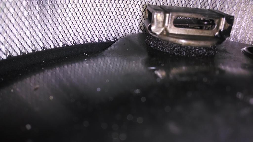
It did not start buzzing until I hooked it up to manifold vacuum.
Anyway, I do not believe my outer trap door system is functioning correctly. Some people say on a cold engine, upon start up, manifold vacuum should slowly pull this door upward, closing off the outer snorkel door and causing air to be pulled up from the opening on the bottom of the snorkel. That makes sense. On mine, before I installed the check valve, as soon as you apply vacuum to this vac motor, it instantly pulls it up hard and fast. Before I installed the check valve, it would stay stuck up in the "heat mode" and would not ever go to "cool mode", no matter how many times I opened the throttle. I assume the "you have to rev the engine to get it to go to cool mode" basically is just disrupting manifold vacuum to this door motor, allowing it to fall back down. With the check valve installed, not sure if it is installed the right way, no vacuum is reaching this motor, so the door is staying in the "cool mode". I am guessing this "check valve" is supposed to let vacuum flow through it; then when you rev the engine, cutting off manifold vacuum, it should not let vacuum flow back through it, if the thermal vacuum sensor is working correctly?
Once I install the new thermal vacuum switch I will do some more diagnostics/try to better understand how this TAC system should be working. But, like I mentioned earlier, we are already into spring here, won't be any more cold weather for a long time. I might not be able to tell if this system is working correctly until next winter, or if I find a big cooler/freezer to park the Scrambler in over night
That's it for now
I changed out the old choke, the internal spring was weak, would not close the choke.
New on top, old on bottom. The new ones metal coil thing is much "springier", works great.
With a fully functional choke again, the cold starts are much easier.
I was missing the "check valve", Jeep Part #J3228426, on the vacuum line going to the outer trap door in my air cleaner. I obtained a new one, from Crown
, and installed it. I have not found anything yet on which way to install it. It is a black/white valve. Anyway, I plugged it in one way, it just allowed vacuum to go right through it and shut the outer door. I installed it the other way, and now the door stays open. I am going to hook this valve up to a vacuum gauge/vacuum source and try to figure out what it is supposed to do. I have not found much information on it A big problem I have right now - our temperatures are staying over 60 degrees, so the outer door should be staying open, which it is now, but I am not 100% sure I actually "fixed the problem" by just sticking this part in.The other part of the outer trap door system, the thermal vacuum switch. Mine looks like this, which is different from all the other ones I have seen:
References to this switch seem to indicate one of these:
http://www.pt374.www.auto-parts-onl...eaner-temperature-sensor-jeep-cj7-ats-17.html
I ordered one of the above switches to install. Mine appears to be working, but it is annoying. Manifold vacuum flows into one port on the bottom of this switch. It flows out the other port to the outer air cleaner vacuum motor depending on temperature. I "assume" that if the temperature is high enough, manifold vacuum is diverted inside the air cleaner, not 100% sure. The outer door is a bit confusing to me. The inner door is simple - manifold vacuum opens it. The outer door, manifold vacuum pulls it to the heat mode, so I assume once it warms up, manifold vacuum should be shut off to this door, allowing it to fall toward the bottom of the snorkel and let it in cool air. That's how it should work.
My existng thermal vacuum switch has this little metal flap on the air cleaner side. It constantly vibrates when the engine is running, making an annoying "buzzing sound". The sound is loud enough to hear with the hood shut, over the idling engine. This picture better shows the metal flap thing:
It did not start buzzing until I hooked it up to manifold vacuum.
Anyway, I do not believe my outer trap door system is functioning correctly. Some people say on a cold engine, upon start up, manifold vacuum should slowly pull this door upward, closing off the outer snorkel door and causing air to be pulled up from the opening on the bottom of the snorkel. That makes sense. On mine, before I installed the check valve, as soon as you apply vacuum to this vac motor, it instantly pulls it up hard and fast. Before I installed the check valve, it would stay stuck up in the "heat mode" and would not ever go to "cool mode", no matter how many times I opened the throttle. I assume the "you have to rev the engine to get it to go to cool mode" basically is just disrupting manifold vacuum to this door motor, allowing it to fall back down. With the check valve installed, not sure if it is installed the right way, no vacuum is reaching this motor, so the door is staying in the "cool mode". I am guessing this "check valve" is supposed to let vacuum flow through it; then when you rev the engine, cutting off manifold vacuum, it should not let vacuum flow back through it, if the thermal vacuum sensor is working correctly?
Once I install the new thermal vacuum switch I will do some more diagnostics/try to better understand how this TAC system should be working. But, like I mentioned earlier, we are already into spring here, won't be any more cold weather for a long time. I might not be able to tell if this system is working correctly until next winter, or if I find a big cooler/freezer to park the Scrambler in over night
That's it for now

FLCJ8
Legacy Registered User
- City
- Palm Bay
- State
- FL
Have you been to this site?
Probably so, as it sounds a lot like what you have said
http://home.sprynet.com/~dale02/list.htm
Probably so, as it sounds a lot like what you have said
http://home.sprynet.com/~dale02/list.htm
- City
- Biloxi
- State
- MS
Have you been to this site?
Probably so, as it sounds a lot like what you have said
http://home.sprynet.com/~dale02/list.htm
Yes
He has some good information, but certain details are lacking, like the above mentioned check valve for the TAC system. But, his site is based off of an '85 model, mine is an '83, so there are some differences
The FSM has some good info, too, but again, some details are lacking, like what direction to put the check valve. IIRC, my '83 FSM does not mention the check valve, but my original under hood sticker shows it
My under hood sticker shows which way to put the two reverse delay valves, but no direction information given for the check valve