• Notice for iPhone users: DO NOT use the image size reduction option when uploading photos to the forum. This causes portrait images to post as landscape. We have added a warning to the image insert pop-up as well.

IAFFCJ 81 Scrambler

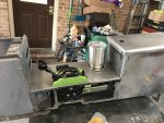
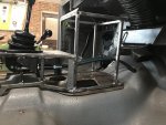
BigWalton was asking about why I had to change plans with the cable shifter routing for the Atlas. Hopefully these pictures help explain it. As you can see above I am building a console for the Scrambler and the reason for this was to put everything within reach even when pinned back in the seat in a precarious position. Due to that final location of the shifters and buttons like the winch control and such were of more importance than the routing of cables to actually make it happen. Now that the console is very close to ready to go to paint I needed to be sure that i wasn't going to need to do something drastic to make everything work.

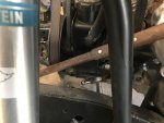
Original plan was to use the hole that is in the tunnel cover already to run the cables through. Turns out no chance that i would be able to make them make the turns using that hole so after some figuring i figured out where the cut the new hole. Nice sweeping bends now and the cables miss everything. They are close to transmission lines but I thing with some chafe protection we will be good to go. Now once console comes back from paint shifters can be hooked up and adjusted. Well adjustments may have to wait until it runs and moves but we are heading in the right direction.
IMG_2748.jpg
 
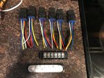
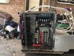
I have added a bank of 6 switches to the dash that have no true plans as of right now I am sure I will find things to hook to them never can have too many light bars right. Well while I am building the console I decided to make a relay plate so all those switches can have relays attached there fore no matter what I want to power with them I can just run a wire and attach it to the buses on the panel and good to go. May have gone with a little overkill with the relays but should be good for anything that I want to power.

Parts to build the panel. Missing the fuse block it is in the garage. going to lay it all out and drill the holes then once back from paint I can wire it all up. Will give me power for the switch panel for both my radios the USB connections and the Cig lighter all with fuses. Relays are a little bigger than I thought but think they will work and they are waterproof.

IMG_2751.jpg
 
One of the last things i am trying to get in the console before paint is at least one cup holder. Once they arrive they are not what I thought they would be however with all the ones I have ordered I think that I can put them together and make some that will work. If they don't do everything you want use more than one and make them what you want. Hope to figure this out tomorrow rubber pieces are warming up right now for force fit.

IMG_2752.jpg
 
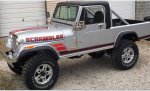
Just going to leave this here so I can find it later. Pretty sure these are the hood decals that I want for the scrambler. Anyone know what year they are from.
IMG_2750.jpg
 
Yeah, I plan on the same graphics on the scrambler, but it will be Olympic white, with those decals and full garnet interior... should be a nice combo with that silver.

cb
 
. should be a nice combo with that silver.

cb

Thanks guys. I think it should look pretty good and should be easier than getting custom ones made to match the other reds I’m using.
 
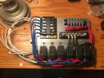
Finished up the console today i am calling it officially ready to go to paint. Hope to get it down to the paint shop next week.

It has been over 15 years from the last time i built a power distribution relay panel. Last one was on a fire truck when I worked at the Saulsbury plant. Came out pretty good I think and should make for easy accessory additions in the future.
IMG_2758.jpg

And it all still fits in the console.
IMG_2759.jpg

And the most important part of this whole project. Cup holder done.
IMG_2760.jpg
 
That is a really clean power distribution panel. Nice work and well thought out. Can't wait to see that console painted and installed. Very impressive.
 
:drool: :drool:

Finished up the console today i am calling it officially ready to go to paint. Hope to get it down to the paint shop next week.

It has been over 15 years from the last time i built a power distribution relay panel. Last one was on a fire truck when I worked at the Saulsbury plant. Came out pretty good I think and should make for easy accessory additions in the future.
View attachment 61591

And it all still fits in the console.
View attachment 61592

And the most important part of this whole project. Cup holder done.
View attachment 61593
 
WOW :eek: That power distribution panel is insane, awesome work!

That said, did you look at any of the options out there for accessory power before deciding to go this route? I did something like you for my switched circuits on the Postal but have now looked at enough of the various aftermarket solutions now that I'll never do it again. sPod, S-Tech, Painless, Trigger and a pile of others.

Just curious if there was a decision process to going this way.
 
WOW :eek: That power distribution panel is insane, awesome work!

That said, did you look at any of the options out there for accessory power before deciding to go this route? I did something like you for my switched circuits on the Postal but have now looked at enough of the various aftermarket solutions now that I'll never do it again. sPod, S-Tech, Painless, Trigger and a pile of others.

Just curious if there was a decision process to going this way.

Honestly Eric I did not look into those and probably would have gone that way if I had. When I built fire apparatus in another life we had relay panels that had a fuse and relay plug and were very easy to wire up and I was looking for something similar but did not have any luck. I am sure I was looking in the wrong places. So I decided to build what I had in my head and happened to have some of the parts in an old lunch box. :rolleyes:

This route also ended up being very affordable I got a great price on all the parts and didn't have to pay for labor with anything but my time.

maybe in the future something else will take its place but for now onward and upward.
 
I am pretty exited to be moving on from the console build. While it was very rewarding im ready to turn some wrenches and get some additional systems finished up. Started on the power steering and hydroboost plumbing today. I ran into some issues with a fitting so it will be a few days before I can finish the plumbing but I have a solid plan and ordered all the fittings I need to add the cooler. I also did the West Texas offroad upgrade to the pump for the hydro assist steering.

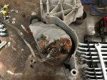
After I figured out that it was easier to pull this entire bracket off the motor rather than just the pump I had the pump out and the original high pressure line came off without issue.

IMG_2763.jpg

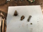
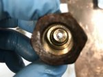
I then pulled the main fitting and the plunger and spring from behind them. It all came out very easily and I only made a little mess on the bench. :rotfl:
IMG_2764.jpg

As for the upgrades I drilled the main fitting out to 5/32 as per the instructions from WTOR.
IMG_2765.jpg

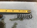
I then pulled the plunger apart and was going to remove the shim however there wasn't one. I decided not to add washer at this time until I can see how it all works. I did stretch the spring to just over 2 inches. I am pretty sure the donor vehicle had hydroboost brakes so I am not sure if that is why there was no shim and the pressure is already
where it needs to be or not. pretty easy to change if needed in the future.

IMG_2766.jpg
 
I love the hydroboost brakes on my Scrambler, It's as different as night and day.
 
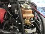
Decided to plumb what I could on the hydro boost today. After I figured out how to work the fittings to make the high pressure lines things went pretty easy. My Power steering reservoir has two return lines on it so I put the hydroboost into the top one and I was planning to run the steering box return into the lower one after it comes out of the cooler but as I got to look at it I wasn't sure that it would clear the steering shaft. So I put the steering coloum in and a stock steering shaft just fit for mock up. The steering box is moved forward with a more mount so stock shaft wouldn't work without modification. It was very close but I have a torch so I heated the line up and moved it to a good place. Should work great now.

IMG_2781.jpg

I also needed to make some lines to reach the brake proportioning valve as the ones we made when we did the frame wern't quite long enough. I am going to get some unions and connect them together on the firewall. This will give me a good place to plumb in a line lock in the future if I want also so mistake worked out. I'm getting better at the line bending not Mysunshine good but defiantly better.

IMG_2787.jpg

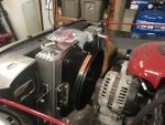
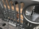
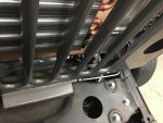
I also mounted the cooler that I am using for the power steering and the radiator. I needed them both in so I can plumb the last of the stuff and make sure everything clears and no rubbing issues occur. It looks like I should be good with clearance and plumbing plan I think will work out also. The rest of my fittings should show up tomorrow so hope to get the plumbing done tomorrow.

IMG_2784.jpg
IMG_2785.jpg
IMG_2786.jpg

I also remounted some computer stuff so it is more secure and I won't have to mess with it again.
 
I'm getting better at the line bending not Mysunshine good but defiantly better.

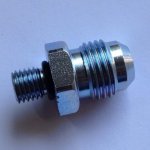
LOL. It takes time to get it to "click". My advantage is that I bend a lot of lines. Actually, that's what I have to do today on a 69 Camaro. :) BTW, you should get a -6 fitting for the hydroboost return fitting. That cleans things up a lot because all of the fittings on the hydroboost would all be -6.
 

Attachments

  • hydroboost spittier fitting.jpg
    hydroboost spittier fitting.jpg
    42.2 KB · Views: 38
Back
Top