• Notice for iPhone users: DO NOT use the image size reduction option when uploading photos to the forum. This causes portrait images to post as landscape. We have added a warning to the image insert pop-up as well.

Spankrjs 1985 Spring Special CJ-7

spankrjs

Scrambler Junkie
Lifetime Member
SOA Member
City
Biloxi
State
MS
I did some more diagnosis, trying to figure out my "slight surge" at light cruising speeds/throttle input.

With the vacuum advance disconnected, the problem goes away 90%. The issue is still there, just not as noticeable. So, I was thinking, maybe the vacuum advance diaphragm was leaking, or the linkage binding up, maybe?

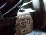
This is the vacuum advance module, on the side of the distributor:
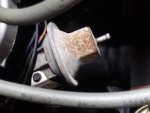
20200210_175420.jpg

The OEM tag that is on it:

20200210_175428.jpg

Basically, engine vacuum, either ported or manifold (depends on year/emissions stuff, check your under hood sticker), pulls on the diaphragm advancing the timing as vacuum increases. This is kind of when I am having my issue, right off idle, into more of a light throttle mode, when the vacuum is increasing, should be increasing the timing.

So, I hooked up my little hand held vacuum pump to the vacuum advance module:
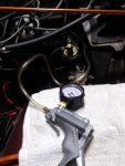
20200210_175500.jpg

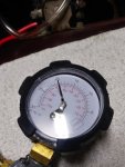
Put 20" of vacuum on it:

20200210_175527_HDR.jpg

The diaphragm held the vacuum for 20 minutes. Vacuum never started to drop, I finally just released the vacuum. So, I am assuming no vacuum leak here.

I pulled off the distributor cap and checked how smoothly the vacuum advance arm was moving. It moves really smooth, I don't think anything is binding up. I was hoping maybe the inside of the distributor had some debris inside, causing an issue, but nope, it is clean.

No vacuum applied, arm rests here:
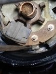
20200210_180321.jpg

Full vacuum applied, arm moves to here:
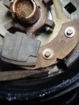
20200210_180334.jpg

Not the best pictures, but the arm moves nice and smooth throughout its entire range of motion. No skips, bumps, erratic movement, nice fluid stroke.

So, I do not think my issue is with the vacuum advance module. This was an easy thing to check. I will probably hook up a vacuum gauge inside the cab to check vacuum while the engine does its "surge" thing. It will only do it under load, part throttle cruising. Idle, hard acceleration, stationary throttle increases, no problems, Starts up and turns off fine.

After looking at the vacuum, I will probably check the fuel pump pressure/discharge capacity. Then, check the carb again. Just kind of funny how this problem just happened, not right after I rebuilt the carb, who knows? Maybe I dropped some old RTV down the carb throat when I was messing with the valve cover re-seal?

Speaking of valve cover re-seal, fail :(
20200203_185709.jpg

Yep, the plastic valve cover started to leak, but only at the back, near the firewall. I am almost wondering if the mushy/shot motor mounts/transmission mounts allowed enough engine movement for the valve cover to hit the heater box stud, jarring the seal loose? Before I proceed with either resealing/replacing the valve cover, I am going to change the engine/transmission mounts. When I was draining/refilling the transfer case I realized that I could actually pick up/lift the entire engine/transmission/transfer case assembly!!! Time for some new mounts.

I was talking about how the vacuum advance is run off either ported/or manifold vacuum, this is how my '85 California emissions model is run:
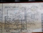
20200210_181606.jpg

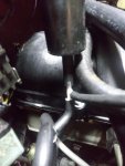
Hard to see, but I have a line that runs straight off the intake manifold, to a small vacuum reservoir, through a forward delay valve, to the adaptive switch. Before the adaptive switch/reservoir/delay valve, the manifold vacuum line "T's" off straight to the vacuum advance module.

So, I am getting full manifold vacuum to the vacuum advance at idle. This is probably due to the under dash computer controlling some of the timing.

IIRC, I set my timing at 8 degrees advance:

1) engine RPM at 1600
2) vacuum advance module disconnected/vacuum line plugged
3) adaptive switch electrical connector unplugged.

When you hook everything back up, I can't remember what the base timing actually is at idle. But, it is higher then the initial 8 degrees. So, you have base timing, plus mechanical advance, plus vacuum advance, PLUS the computer controlling some of the timing.

On the computer affecting the timing, this is why when people do the "nutter bypass" you have to remove one wire from the ignition control module. This is how the under dash computer controls some aspects of the timing, via the ICM which talks to the pick up coil assembly inside the distributor. I am assuming the computer is using the pick up coil as a rudimentary "cam position sensor"?

After I check out the possibility of any fuel issues, I will recheck all the timing stuff, and map out the mechanical/vacuum advance curves.

That's it for now :wave:
 

spankrjs

Scrambler Junkie
Lifetime Member
SOA Member
City
Biloxi
State
MS
I did some more diagnosis work last night.

First, I wanted to check manifold vacuum, while driving. I wanted to see if I had steady manifold vacuum throughout various RPM/driving conditions, especially when the surge occurs.

I inserted a plastic "T" at my manifold vacuum line, right before the little vacuum canister:

20200211_170209.jpg

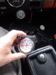
I had a really long length piece of vacuum tube, which I connected to my "supposed to be mounted in the dash but I keep it loose for diagnostic stuff" vacuum/boost gauge, voila:

20200211_170714.jpg

The picture above is showing manifold vacuum, while the choke is on the 2nd step fast idle, around 900 RPM. 22" here, 24" at base idle RPM of 650.

Manifold vacuum highest at idle, drops as you smash the gas and the throttle plates open. Vacuum steady, smooth drop as you accelerate. Manifold vacuum DOES fluctuate when the engine surges at light throttle, between 10-18". Vacuum fluctuation matches the engine surge, so I am thinking the vacuum fluctuation is a "symptom", not a "cause" for my issue.

I just tested "manifold vacuum", I might go back and test "spark/ported vacuum", but I would imagine the results will be the same.

So, no vacuum leaks anywhere, steady manifold vacuum EXCEPT when the engine surges. I am going to "ASSUME", for now, that the steady vacuum reading is telling me that I do NOT have some weird vacuum leak some where. If necessary, I will revisit this potential vacuum leak scenario.


Next, decided to test fuel pump pressure and volume. I did not think this was the cause of my issue, but worth testing to eliminate the possibility.

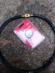
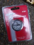
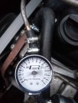
My fuel pressure tester gauge is for "high pressure fuel injection" applications, NOT for low pressure carb fuel pressure. So, $35 in parts later I had a "low pressure" fuel pressure tester:

20200211_172246.jpg

20200211_172249.jpg

20200211_172944.jpg

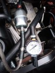
Basically, cheap fuel pressure gauge, 1/8 NPT "T" and two 1/8 NPT hose barbs, some fuel line and clamps.

NOTE - some people mount these gauges permanently under the hood. NO way I would trust one of these cheap gauges to sit on top of a hot engine. Too great a risk for a fire.

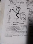
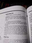
Anyway, FSM fuel pressure testing procedures:

20200211_173236.jpg

At first, I mounted the pressure gauge between the filter and carb, bad idea. The gauge fluctuated terribly due to the excess fuel trying to flow back to the return port on the filter:

20200211_173842.jpg

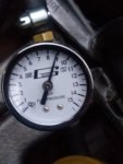
So, I removed the filter, installed gauge, got this reading:

20200211_174629.jpg

This is higher then the 5psi mentioned in the FSM, BUT I am also "dead heading" the pump because I took the return line out of the loop. I am assuming my pressure is fine.
 

spankrjs

Scrambler Junkie
Lifetime Member
SOA Member
City
Biloxi
State
MS
Next, I tested fuel pressure volume:

20200211_173259.jpg

Both testing procedures are from my 1983 FSM. Interestingly, my 1985 FSM does not have these testing procedures??

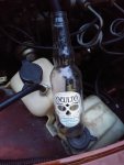
One pint is 16 ounces. I did not have a 16 ounce container, so I figured a 12 ounce beer bottle would be good enough:

20200211_175032.jpg

I ran a piece of hose from the metal fuel line straight to the beer bottle:

20200211_175038.jpg

The carb will idle for awhile with its float bowl full. Anyway, in 18 seconds I had 12 ounce of gas, so no doubt in 30 seconds I would have had at least 16 ounces/1 pint:

20200211_175114.jpg


So, I am pretty confident that my fuel supply/pressure, at least to the needle and seat, is good to go.

Even though I have "screwed around" with the idle mixture screws recently to see if a slightly enriched the mixture would eliminate the surge, it is till almost dead on. Note that the stepper motor pins are close to center at idle:

20200211_181941_HDR.jpg

20200211_181948.jpg

If you rev up the engine, they move around. If you hold the engine at high RPM, then manually shut the choke plate, causing a lean condition, the pins will move to the full rich side.

I am thinking that my issue is inside the carb, either a metering pin setting, trash somewhere, not sure. More diagnosis work needed.


I have been working through the FSM trouble shooting procedures, not necessarily in order:

20200211_201216.jpg

From the above picture:

2, 4, 5, 10, 11, 12 all check out OK.

Still to check:

1 - float level inside carb
3 - inside carb
6 - check all timing (base, mechanical advance, vacuum advance, computer advance)
7 - 9 - inside the carb stuff
13 - pain in butt to check, but I do have the handy dandy AMC Feedback tester tool!!!

Anyway, I will probably check all the timing stuff next, then pull off the carb.

I am thinking I have a carb issue, but only one way to find out. My issue seems to be right around the time the carb should be transitioning completely off the idle circuit.

That's it for now :wave:
 

spankrjs

Scrambler Junkie
Lifetime Member
SOA Member
City
Biloxi
State
MS
Had a little time on Saturday, and no rain for a change, so checked the ignition timing.

20200215_093311_HDR.jpg

Used my older timing light/tachometer.

With the feedback carburetor and computer functional, there are a few steps to take before checking the timing:

1) Warm up engine
2) Disconnect/plug the vacuum advance line
3) Unplug the wire connector from the 4"/10" vacuum switch on the fire wall (if not, the computer will mess with the timing)
4) Hold the engine at 1,600 RPM.

OK, with all of that done, I was at 20 degrees advance, it should only be at 8. When I went to loosen the distributor, the hold down bolt was a little loose. So, I am thinking the last time I checked the timing, I left the bolt a little loose, and the distributor was slowly advancing itself.

Hard to see the timing marks with the radiator/water pump/front accessories in place, but this is what the timing scale looks like on this '85:

20200215_093422.jpg

Amazingly, I took the above picture with the engine off, and the timing mark on the crank pulley lined up exactly where it was when I was checking the timing, 20 degrees advance. What are the odds of that!!!!!

And here is one on an '83 engine in my garage:

20200215_093616.jpg

In hind sight, the next time I have the front of this engine off, I am going to paint the 8 degree mark so it is easier to see.

So, this thing obviously had way too much initial advance. With the base timing set at 20, and manifold vacuum adding around 12, I was sitting at 32 degrees advance at idle. I never checked, but I am assuming the computer might have been trying to retard it some :shrug:

Anyway, set the timing to 8 degrees advance, turned off the engine, reconnected the vacuum advance and the 4"/10" vacuum switch. Interestingly enough, my "static idle" advance was right at 20, 8 degrees initial plus 12 degrees from the vacuum advance (manifold vacuum).

So, that cured my "slight surge at cruising speed/light acceleration"? NO.

It made it almost go away, but it was still there.

Before I pulled the carb off. I got out some carb cleaner. I did the old "rev the engine up, cover up the carb with a towel so the engine sucks really hard and hopefully pulls out any crud stuck in some tiny port some where and makes it run good again" trick. That cured it.

So, timing way out, assuming a partial carb blockage some where, running great again.

The interesting thing about the timing being that far advanced, the engine always turned off and on instantly. No hard starts or "dieseling" when it was shut off. I am assuming the under dash computer must have been retarding the timing some :shrug:
 

Randyzzz

Blown Budget
BENEFACTOR
Gold Member
Lifetime Member
SOA Member
City
Redmond
State
OR
Awesome! Interesting how a couple it was a couple of seemingly small issues!
 

spankrjs

Scrambler Junkie
Lifetime Member
SOA Member
City
Biloxi
State
MS
After all the work to get it running correctly, decided to do some easy work.

The engine/transmission were really moving around a good bit, so I decided to swap out the engine/transmission/torque arm mounts. I used polyurethane, which I have used in all my other Jeeps without problems. I wouldn't mind trying rubber mounts, BUT all of the stuff you buy today is crap and lasts less then a year.

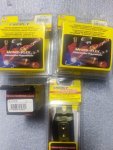
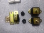
I used Energy Suspension brand parts:

20200216_095901.jpg

Motor mount part#:

20200216_095907.jpg

Transmission mount part #:

20200216_095910.jpg

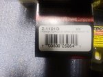
Torque arm bushing part #:

20200216_095914.jpg

What the stuff looks like out of the packaging:

20200216_100220.jpg

Important note on which way to mount the transmission mount, which I ignored, and then had to go back and switch around:

20200216_100224.jpg

I started with the transmission mount/torque arm bushings first. I was able to reuse the torque arm stud, it was in good shape.

To change these mounts, I simply unbolted the transmission mount/torque arm stud from the skid plate, then used a bottle jack on the Dana 300 tail housing to raise the assembly up off the skid plate. Then, just a matter of unbolting stuff. I did NOT drop the skid plate. You can, and it makes it a bit easier, but I prefer not to remove the skid plate unless I have to. Don't jack it way up, or the engine fan can hit the fan shroud and or radiator.

Years of motor/gear oil leakage are fun to deal with:
20200216_111302.jpg

The transmission mount that was in here was secured to the skid plate with studs. This makes it easier to get it aligned, but they also hang down further then bolt heads. Not that this Jeep is going rock crawling anytime soon, I just prefer bolts.

20200216_114945.jpg

How the torque arm goes together:

20200216_114956.jpg

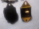
New vs old transmission mount, the new one is probably 3/16" taller:

20200216_115006.jpg
 

spankrjs

Scrambler Junkie
Lifetime Member
SOA Member
City
Biloxi
State
MS
A few reference shots of the part #'s I found on the old transmission mount/torque arm bushings. Not sure if they are OEM or aftermarket:

20200216_115030.jpg

20200216_115052.jpg

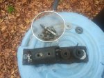
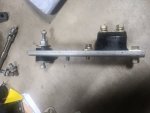
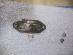
When I pulled all the transmission mount parts off, I made an important discovery: The transmission mount bolt closest to the torque arm was completely missing!! This was probably the biggest cause of my power train movement issues. In the picture below, left to right: big hole for torque arm mount/bolt that holds steel plate to transmission foot/missing transmission mount to transmission foot bolt/and outer transmission mount bolt.

20200216_115134.jpg

Picture of how it all goes together, note that the torque arm stud looks short:

20200216_121648.jpg

What I do, and I am not saying it is correct, but I have done this with my red Scrambler with over 40,000 miles on it: I shim the torque arm stud with washers to keep it tight between the skid plate/metal bracket. This takes some trial and error to get it tight. I do not like how the factory configuration allows so much slop. The way I do it, this torque arm mount is like another smaller transmission mount, and keeps the power train from excessively "torquing over". Again, not saying this is "correct", just how I do it.

20200216_123959.jpg

With the transmission/torque arm mounts installed, I moved forward to the motor mounts. Again, I used a bottle jack under the oil pan, and changed one side at a time. Again, do not jack too high or you will break stuff. I did the passenger side first. I found it easiest to remove the upper motor mount bracket from the block, too. This gave me enough room to get everything removed/reinstalled without jacking the engine up so high that the fan would jam into the shroud.

20200216_151328.jpg

Old vs new:

20200216_151339.jpg

And again, don't do what I do and forget to install these steel plates between the top of the motor mount and the bottom of the block mounted brackets. Pretty sure they are necessary due to the shape of the bottoms of the block mounted motor mount brackets. Nothing like thinking you are finished and see one of these plates on the ground LOL.

20200216_152109.jpg

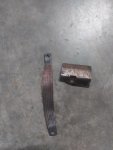
One neat thing on the driver side: besides the grounding strap, this Jeep still had this heat shield to protect the driver side motor mount from the exhaust pipe heat. I have not ever found one of these before on any of my Jeeps. I will take a picture of it installed and post a picture later.

20200216_170753.jpg

So, after having to spin the transmission mount around, and redo the driver side engine mount because I forgot the steel plate, finished.

Will need to wait for a break in the rain for a test drive.

As for the poly mounts, I always hear people talking about how much harder they are then rubber. Probably true. BUT, the rubber engine/transmission mounts that came off of this thing are rock hard, harder then the poly!!!!

As for vibrations, my red/green Scramblers are as smooth as a new car, no weird power train vibrations transmitted through the poly mounts. I would not mind trying rubber mounts, IF anyone made good quality replacements. The last rubber transmission mount I used lasted two days on the dunes in Michigan!!

Again, your results may vary :twocents:
 

spankrjs

Scrambler Junkie
Lifetime Member
SOA Member
City
Biloxi
State
MS
This is a picture of the installed, assuming OEM, heat shield that protects the driver side motor mount:

20200219_072054.jpg

You can see the grounding strap on the left motor mount bolt, the het shield is held in place by the right motor mount bolt.
 

spankrjs

Scrambler Junkie
Lifetime Member
SOA Member
City
Biloxi
State
MS
I had mentioned earlier, that even after all my careful work, my plastic valve cover started leaking from the back corner. Fun.

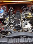
So, start with all this crap in the way:

20200218_173401.jpg

Front stuff to be removed - fuel line, vacuum line, upper radiator hose, heater hose, pcv valve and hose:

20200218_174053.jpg

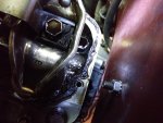
Much more in the rear - heater hose, pulse air hose, more vacuum lines, pcv intake hose, valve cover mounted solenoid trio, 10"/4" vacuum switch on fire wall:

20200218_174058.jpg

And, air cleaner/associated wire pugs and vacuum hoses, serpentine belt idler pulley assembly:

20200218_184249.jpg

When I removed the cover the first time, the RTV seal was at least 10 years old. This time, maybe a month.

Well, the cover would not break free from the head. I tapped on it, tried to get a thin scraper blade to break the seal, no bueno.

I eventually started smacking the valve cover, HARD, with a sand filled rubber mallet. Would not budge. Instead, the plastic cover broke:

20200218_184257.jpg

I hated to break it, I was actually going to try to re-seal it. Once it broke, game over. Even with "the gloves off", this damn thing would not come off. I tried to pry it off, just broke off more plastic:

20200218_184309.jpg

Finally got an edge up, used a big pry bar, just broke the cover more, the seal would not break!!!

20200218_185323.jpg

Yes, the cover is cracking in half, the seal will NOT break free!!!

20200218_185725.jpg

Got half of it off, unbelievable.

20200218_193414.jpg

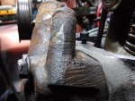
Finally got the other half mostly off, and still had a big chunk stuck to the head!!!!!!!!!!

20200218_194044.jpg

The thing that sucks - 98% of this cover was perfectly glued down, no way it was leaking. The plastic on the OEM covers is actually pretty damn tough. What is amazing, the RTV bond was stronger then the plastic. All my prep work paid off, obviously, but I missed a spot, so all for nothing.

I did not want to destroy the OEM valve cover, but there was no other way to remove it. Sucks.
 

spankrjs

Scrambler Junkie
Lifetime Member
SOA Member
City
Biloxi
State
MS
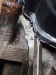
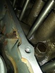
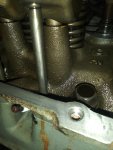
Like I mentioned above, 98% of the seal must have been perfect. Hard to judge after prying the cover off, but you can tell I had a good bead/seal:

20200218_194902.jpg

20200218_194910.jpg

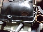
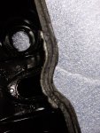
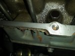
The back end near the firewall, where it was leaking, does not look good, you can actually see oil in the RTV:

20200218_194920.jpg

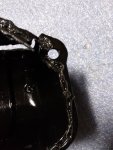
And the rear cylinder head:

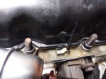
20200218_194959.jpg

In the picture above, you can see where there is no seal around the outside of the bolt hole, and a thin gap/cut in the seal right above the rear bolt hole. I am assuming that is where it was leaking from.

Anyway, no sense crying over spilled milk. It just sucks that I was so close, yet so far away. But, maybe this proves you can get the plastic valve cover to seal up with RTV, I just wasn't careful enough :shrug::twocents::(
 

bigwalton

Alaskan Postal nutjob
FORUM MANAGER
SOA Member
City
Dexter
State
MI
Like I mentioned above, 98% of the seal must have been perfect. Hard to judge after prying the cover off, but you can tell I had a good bead/seal:

View attachment 80087

View attachment 80088

The back end near the firewall, where it was leaking, does not look good, you can actually see oil in the RTV:

View attachment 80090

And the rear cylinder head:

View attachment 80092

In the picture above, you can see where there is no seal around the outside of the bolt hole, and a thin gap/cut in the seal right above the rear bolt hole. I am assuming that is where it was leaking from.

Anyway, no sense crying over spilled milk. It just sucks that I was so close, yet so far away. But, maybe this proves you can get the plastic valve cover to seal up with RTV, I just wasn't careful enough :shrug::twocents::(

:eek: Not quite. IMO, it proves the plastic is never worth reinstalling. Suppose it didn't ever leak but you needed to get in there for maintenance work. You would have had to break it just the same. That's not acceptable to me :shrug:

Totally admire the idea and all the careful work but there's got to be a limit.
 

Belizeit

CJ-8 Member
Gold Member
City
River Ridge
State
La
Dropped one many years ago about 3 feet to the garage floor, shattered, very brittle plastic
 

spankrjs

Scrambler Junkie
Lifetime Member
SOA Member
City
Biloxi
State
MS
Dropped one many years ago about 3 feet to the garage floor, shattered, very brittle plastic

Not this one. I could have hit a cast aluminum valve cover with this sucker and it would have destroyed the aluminum valve cover :eek:

Chuck Norris would have approved of this one :thumbsup:
 

spankrjs

Scrambler Junkie
Lifetime Member
SOA Member
City
Biloxi
State
MS
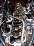
Two hours of scraping/sanding/wiping down, and picking out pieces of RTV/plastic from the cylinder head/rocker arms, ready for a new cover:

20200219_221742.jpg

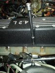
I am going to install one of the ubiquitous "Made in China" aluminum valve covers, the type that says "4.2". I was going to spend more for one of the "Mopar approved" "Jeep" stamped valve covers, till I realized that they are made in China, too :(

Anyway, I have had good luck with the cast aluminum "4.2" valve covers in the past, hope my luck holds out :fingerscrossed: I had over 35,000 leak free miles on my Red Scrambler valve cover, right up till a piston skirt cracked and I swapped in 4.0.

Anyway, I'll post some more information/pictures if anyone is interested.

That's it for now :wave:
 

spankrjs

Scrambler Junkie
Lifetime Member
SOA Member
City
Biloxi
State
MS
So, just simply bolt on a new aluminum valve cover? Oh no, never that easy. Most of the work I am about to show is fairly simple, but necessary, to get one of these valve covers to work. I have installed 5 or 6 of these over the years, and I will say that the quality of these valve covers has gone down hill. Lots of pictures and information, so bare with me.

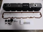
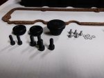
This is what you get when you order one of these "4.2" valve cover: valve cover, gaskets, bolts, screws, oil fill cap, grommets, instructions

20200222_092728.jpg

20200222_092737.jpg

On this 1985 Jeep, the front two holes and the three holes on the passenger side of the head were already present and threaded. I only needed to tap threads into the two exiting plastic valve cover locating holes on the driver side. Your results may vary. On one 50,000 mile original 1982 CJ-7, I had to drill and tap all seven holes!!

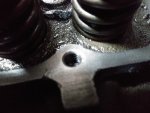
On the two driver side holes, they are directly over a water jacket. I do not recommend drilling these holes any deeper then what they already are.
When I went to drill out these two holes with the 17/64" drill bit for the 5/16" - 18 tap, the bit went right in. So, I did not drill these holes out, I tapped them as they were. Even though the holes were a hair oversize, the tap was a tight fit, I am confident the threads will hold, especially considering that this is just valve cover torque.

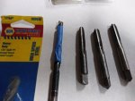
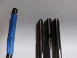
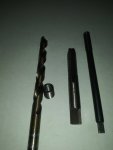
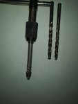
Bits and taps. The regular 5/16"-18 tap wont work, it bottoms out before cutting threads. So, I used the bottom tap first, then the plug tap.

From left to right: drill bit, regular tap, bottom tap, plug tap

20200222_093220.jpg

Not much difference between the bottom and plug tap, BUT the bottom tap did thread a few more grooves.

20200222_093305.jpg

And the two driver side holes tapped, plenty of threads for the valve cover bolts:

20200222_093349.jpg
 

spankrjs

Scrambler Junkie
Lifetime Member
SOA Member
City
Biloxi
State
MS
So, I now have 7 threaded holes. Next, I wanted to see how the included hardware would work with the existing head threaded hole depths. The valve cover flange and gasket are approximately 1/2" thick.
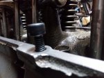
Front bolt threaded all the way in, good to go:

20200222_093842.jpg

Rear hole, same as the front, good to go:

20200222_093859.jpg

Passenger side front hole, a bit shallow:

20200222_093915.jpg

Passenger side center hole, good to go:

20200222_093927.jpg

Passenger side rear hole, a bit shallow:

20200222_093937.jpg

The two holes on the driver side are barely adequate:

20200222_093949.jpg

20200222_094012.jpg

So, I made a little "Redneck Ray" chart:

20200222_094058.jpg

"Stick up" - distance from face of head to bottom of Allen bolt
"Depth" - how deep the holes are
"Flange" - how thick the new valve cover/with gasket is
"Compression" - how much I can theoretically "smush" the new gasket, given the depths of the holes/length of hardware

Front and Rear holes are good to go.
Passenger side center is good to go.
Passenger side front and rear are no good.
Driver side holes are OK. I would like more, BUT I am not going to risk drilling through the head into the water jacket

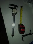
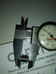
I used my old caliper and a tape measure to obtain my numbers:

20200222_095108.jpg

Every engine is a little bit different, in my experience.
 

spankrjs

Scrambler Junkie
Lifetime Member
SOA Member
City
Biloxi
State
MS
On the passenger side, the center hole is good. I can get good compression here:

20200222_095131.jpg

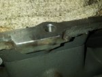
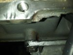
The front and rear holes on the passenger side had incorrectly installed Helicoils. The bolts felt a bit loose in these two holes.

20200222_095143.jpg

20200222_095208.jpg

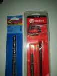
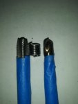
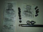
In case you did not know, a Helicoil is a tool/thing to repair damaged threads. A Helicoil kit will come with Helicoils, a special tap, and an install tool. You will usually have to buy the correct drill bit separately:

20200222_095353.jpg

20200222_095512.jpg

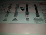
And the instructions: Drill the hole, tap the hole, install the Helicoil, break off the little tang, Finished:

20200222_095527.jpg

To remove the two old Helicoils, I drilled out the Helicoil some, then used an extractor, worked like a charm:

20200222_101015.jpg

20200222_101024.jpg

When I re-tapped, the first hole, and installed a new Helicoil, problem:

20200222_101958.jpg

The existing holes are not deep enough to correctly install the Helicoils. This is probably why the old Helicoils were loose, they were cut short.

So, measured the length of a new Helicoil:

20200222_095541.jpg
 

spankrjs

Scrambler Junkie
Lifetime Member
SOA Member
City
Biloxi
State
MS
I had to drill these two cylinder head holes deeper then the Helicoil length, so that I could fully thread the hole. The Helicoil tap is NOT a bottom/plug tap, so the hole has to be deeper in order to fully thread to the depth of the Helicoil. IIRC, I drilled these two holes 9/16" deep:

20200222_105937.jpg

And installed, worked perfectly. The Helicoils sit a turn below the surface, so perfect:

20200222_110532.jpg

20200222_110553.jpg

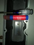
The Helicoils are stainless, so a magnet will NOT pick up the little tang that you break off once they are installed. A little 3M weather strip glue on the end of an old spray can straw worked perfect:

20200222_110622.jpg

Now, good depth on these two holes:

20200222_114411.jpg

Revised "Redneck Ray" chart, showing the increase, circled:

20200222_114424.jpg

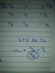
The Helicoil tap is an "STI Tap". A bottom tap, in this flavor, would be much better. NAPA could not get one, I am sure they are available from a machinist supply house?

20200222_114645.jpg
 

spankrjs

Scrambler Junkie
Lifetime Member
SOA Member
City
Biloxi
State
MS
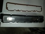
Finally, 7 correctly drilled/tapped holes.

Let's look at the valve cover. Remember I mentioned Quality?

20200222_115435.jpg

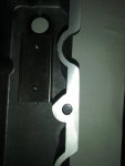
Yep, one of the holes in the flange was not drilled out LOL:

20200222_115442.jpg

Easy enough to fix.

One other potential issue - make sure these screws are red Lock Tite'd into place, you do not want them falling out:

20200222_120051.jpg

On previous covers, thee screw have all been loose. On this one, they came permanently installed.

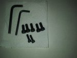
The hardware that comes with the kit, the 5/16" and 1/4" cap screws, for some reason, have a Metric allen head socket up top?

20200222_122952.jpg

Which sucks for me, since all I have are Metric Allen headed wrenches:

20200222_123019.jpg

So, I went to Lowes, bought replacement hardware, that uses SAE allen head sockets:

20200222_123107.jpg

20200222_123152.jpg

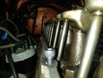
In the above picture, you could use a ratchet on the driver side. This will not work on the passenger side, not enough clearance next to the valve cover. So, I ended up having to use Allen wrenches anyway, which is better, less risk of over torquing the bolts. At least I have SAE stuff installed, won't have to carry around metric allen wrenches.
 
Top