

You are using an out of date browser. It may not display this or other websites correctly.
You should upgrade or use an alternative browser.
You should upgrade or use an alternative browser.
Another Scrambler Purchase/Road Trip - UPDATE- BODY ON FRAME AGAIN
- Thread starter spankrjs
- Start date


- City
- Biloxi
- State
- MS
Once again, amazing work, photo documentation, and attention to detail.
From your pics I have determined that a dangly hose + cap is my tcase vent, it *should* mount to the firewall, and it's too short to do that right now. Another chore looms!
So you *are* going to take this on a nataionwide member-by-member visitation tour once you're finished, right? Seafood and beach await you in Virginia!
Glad my pics could help

Appreciate the offer, might just have to take you up on that some day

- City
- Biloxi
- State
- MS
Brisket barbeque awaits in Texas. And if you are a hunter.... 12 point hunt as well
Appreciate it
- City
- Biloxi
- State
- MS
Between getting stitches pulled from my gums on Friday, then going Jeeping all day Saturday in the TJ Rubicon, I just got a little work done, mainly on the wheels.
Used a compass to draw a template on cardboard. 7" outer diameter, 4 1/4" inner circle.
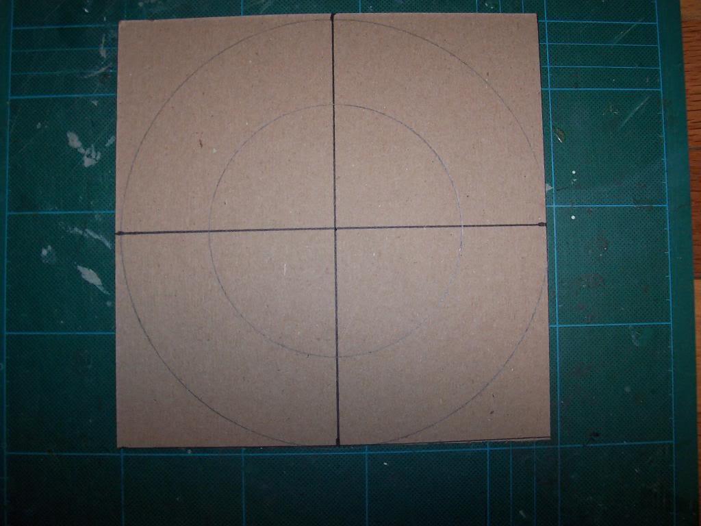
Cut out the template.
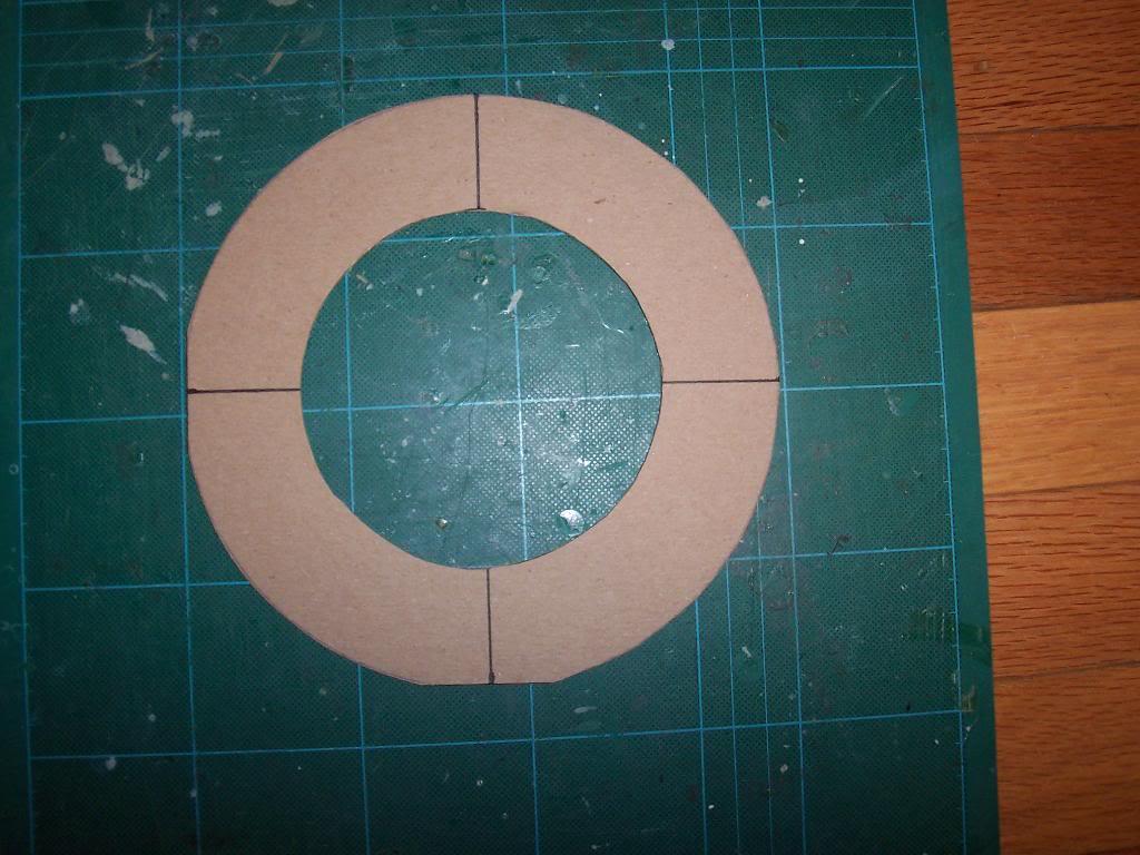
I used a spare wheel hub to get the lug nut hole dimensions from.
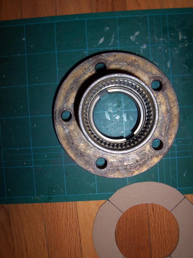
Clamped the cardboard template to the wheel hub and used an exacto knife to cut out the wheel lug openings.
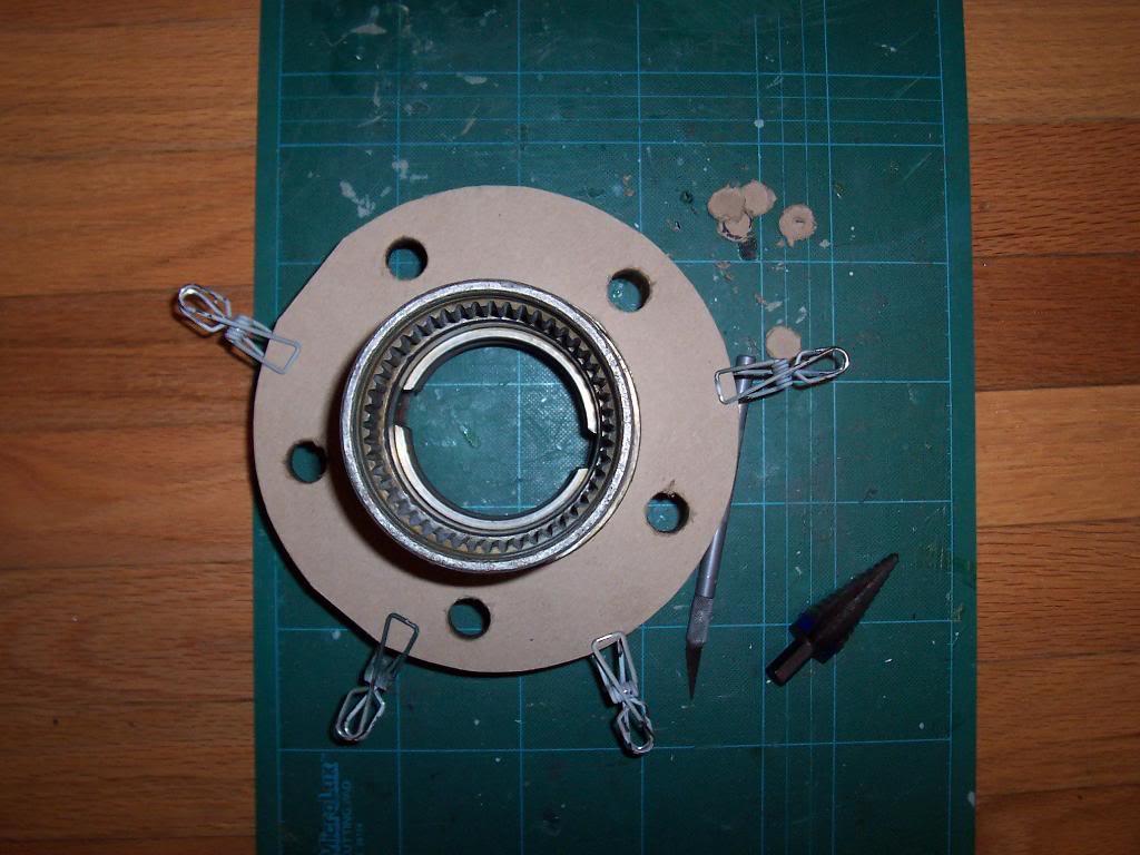
"Bolted" cardboard template to a 8" wheel to make sure it fits. Used some old lug studs to positively secure the cardboard template to the wheel.
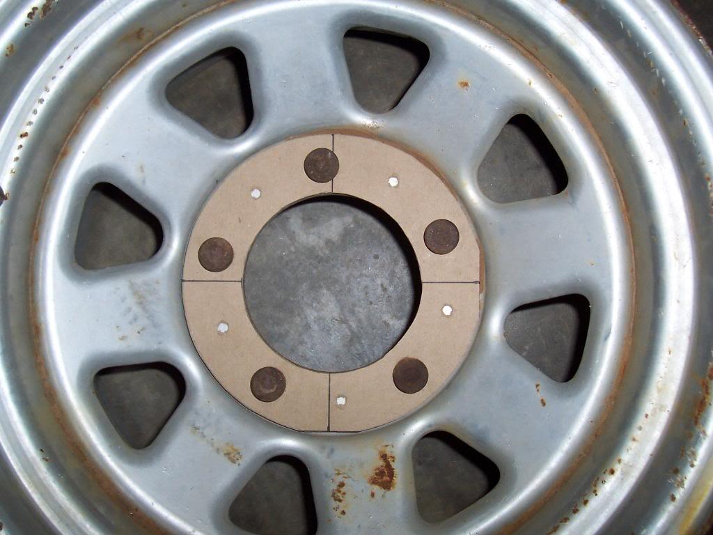
Placed cardboard template back on 7' wheel so that I could cut out the center cap holes.Used a 7/32 drill bit to drill the holes through the cardboard template.
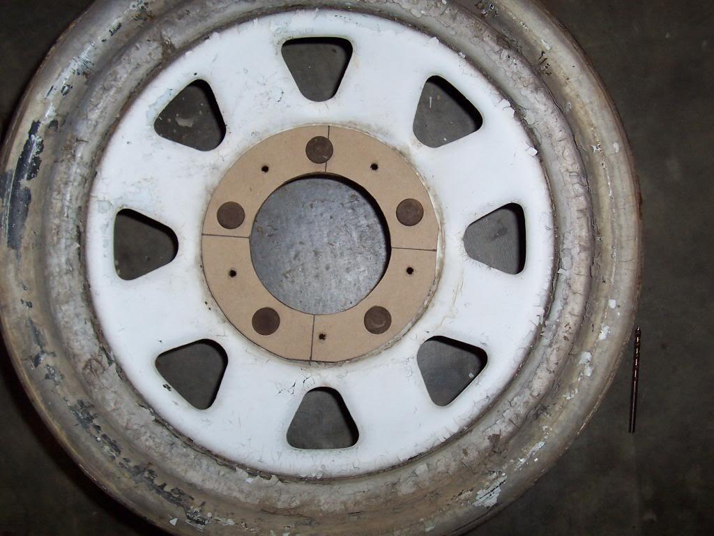
Traced my cardboard template onto a piece of 22 gauge sheet metal.
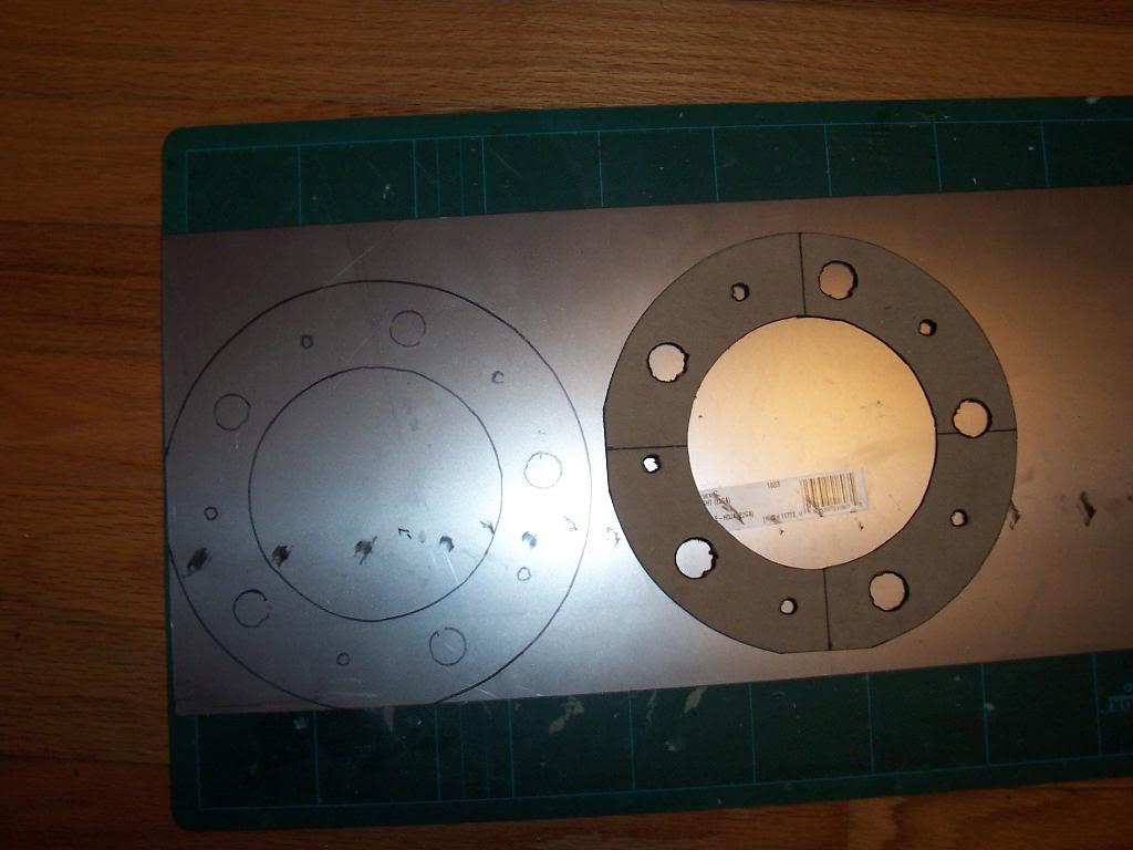
Bolted the steel template to the old 7" wheel that has the center cap holes. I didn't want to just transfer these holes from the cardboard to the steel template. It was easier to mount the steel template and drill the holes in place.
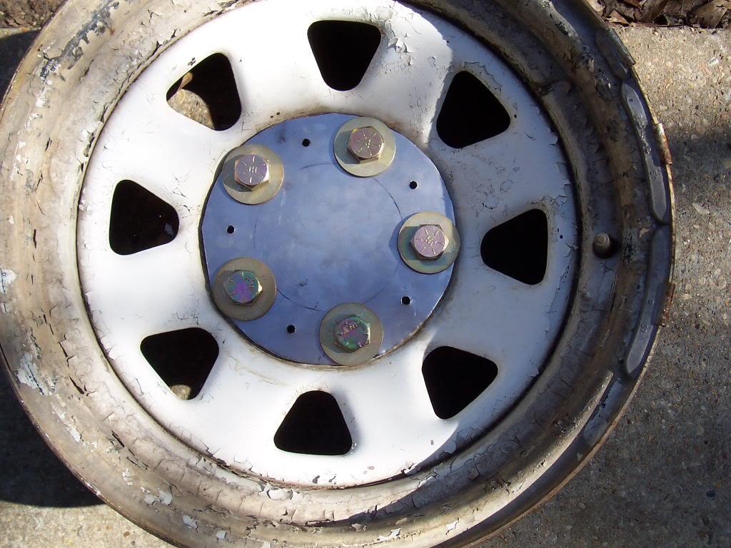
I then bolted the steel template to one of my new 8" wheels.
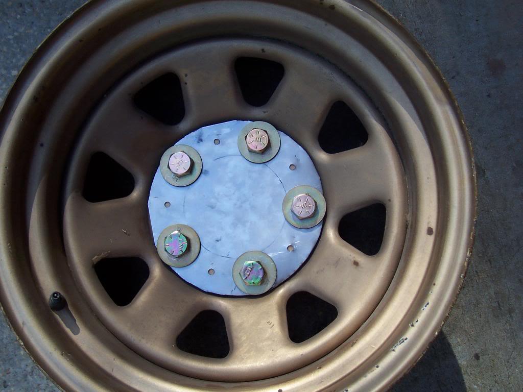
Then center punched the holes.
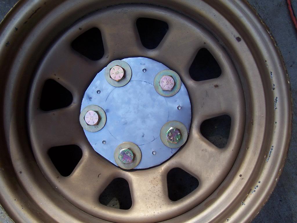
Used a compass to draw a template on cardboard. 7" outer diameter, 4 1/4" inner circle.
Cut out the template.
I used a spare wheel hub to get the lug nut hole dimensions from.
Clamped the cardboard template to the wheel hub and used an exacto knife to cut out the wheel lug openings.
"Bolted" cardboard template to a 8" wheel to make sure it fits. Used some old lug studs to positively secure the cardboard template to the wheel.
Placed cardboard template back on 7' wheel so that I could cut out the center cap holes.Used a 7/32 drill bit to drill the holes through the cardboard template.
Traced my cardboard template onto a piece of 22 gauge sheet metal.
Bolted the steel template to the old 7" wheel that has the center cap holes. I didn't want to just transfer these holes from the cardboard to the steel template. It was easier to mount the steel template and drill the holes in place.
I then bolted the steel template to one of my new 8" wheels.
Then center punched the holes.
Last edited:
- City
- Biloxi
- State
- MS
And then, the moment of truth, I drilled the holes into the 8" rim.
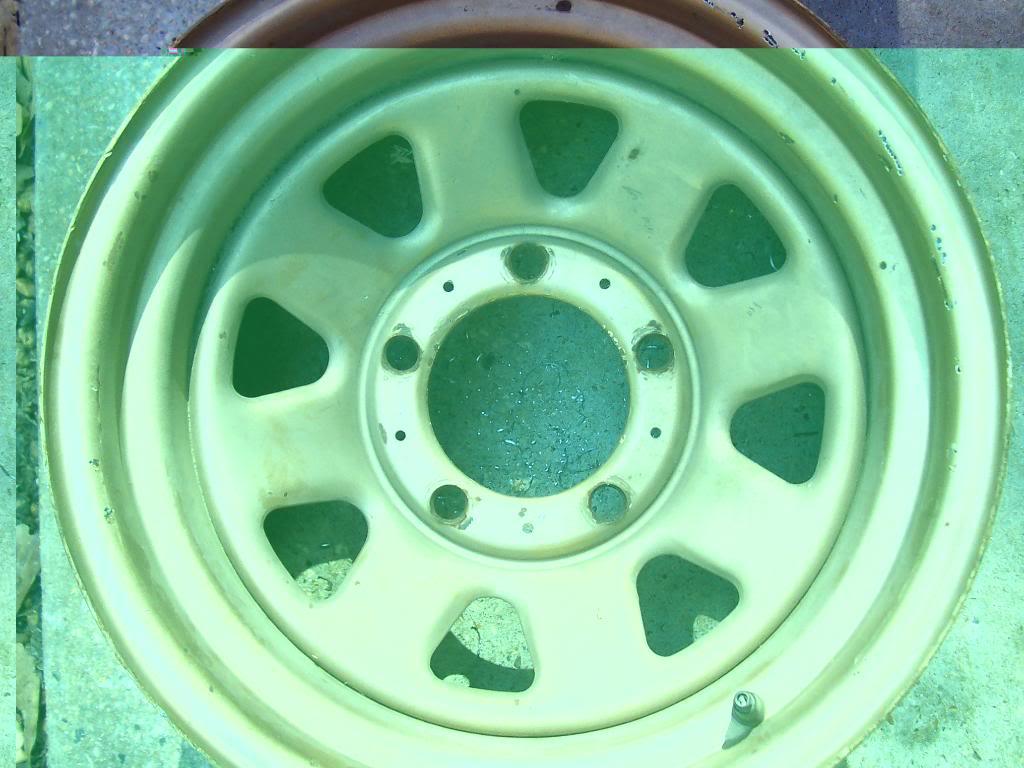
And the center caps bolt on.
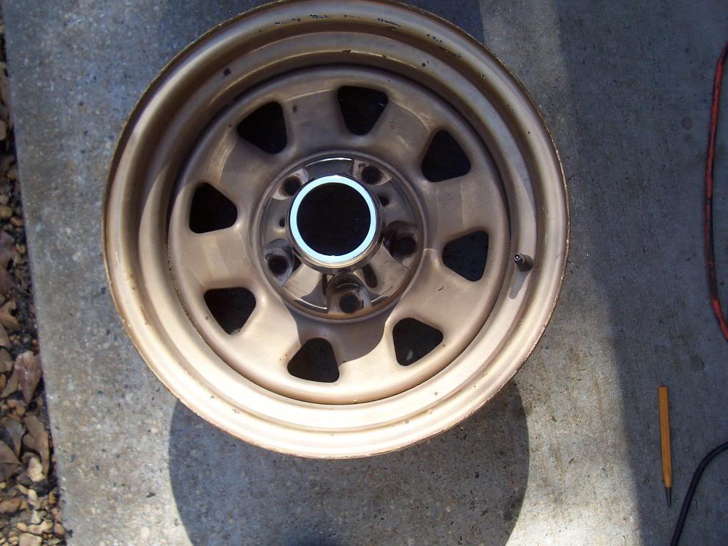
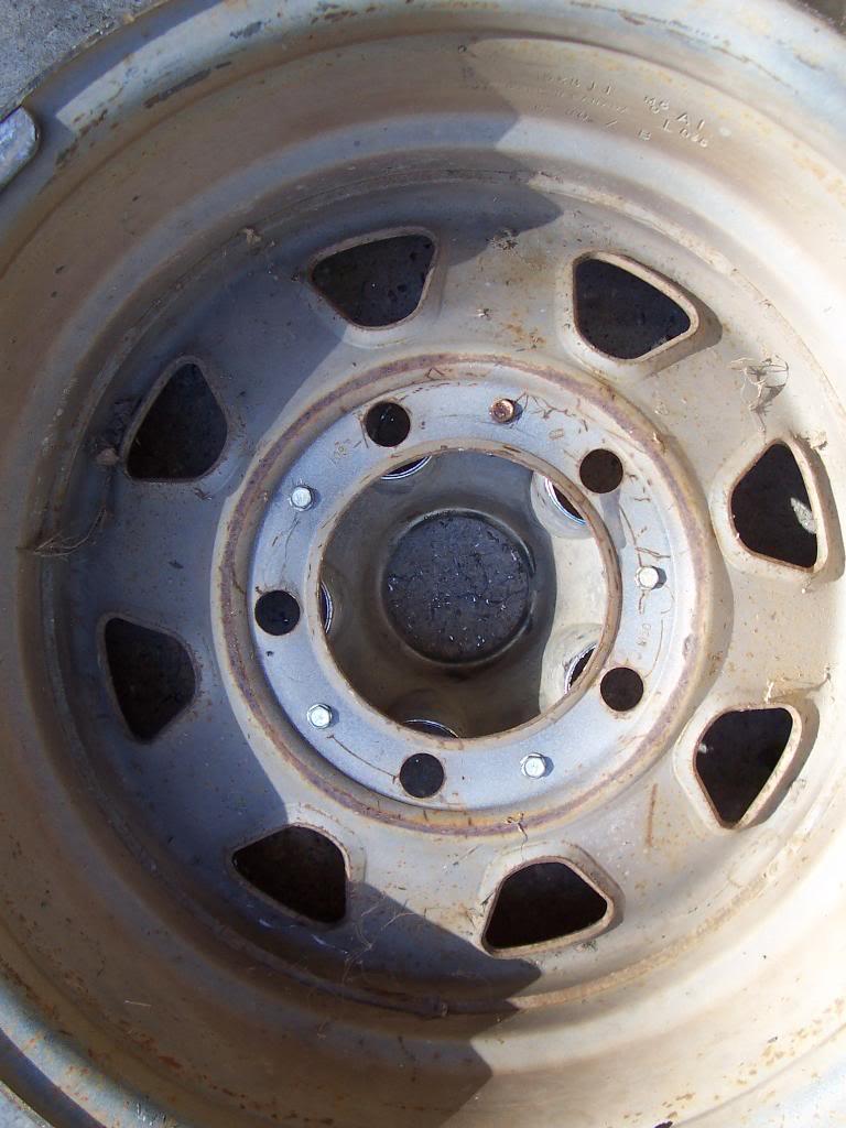
I then drilled the 4 other rims. Not exactly sure if this is the "best" way to do this, but it worked out perfect for me. The most important step in this entire procedure is center punching the holes before you drill. You need to get the punch exactly centered in the hole in the template. All 5 of my rims worked out perfectly, center caps bolt onto all 5. I was concerned about the caps fitting slightly off onto the wheels, but even the factory rims with holes and the threaded holes in the back of the center caps allow room for adjustment. The holes in the rims are 7/32 from the factory and center caps use a #10 screw, so there is a little bit of play between each rim hole/center cap threaded hole interface.
Now I need to get the rims blasted and painted.
Thats it for now.
And the center caps bolt on.
I then drilled the 4 other rims. Not exactly sure if this is the "best" way to do this, but it worked out perfect for me. The most important step in this entire procedure is center punching the holes before you drill. You need to get the punch exactly centered in the hole in the template. All 5 of my rims worked out perfectly, center caps bolt onto all 5. I was concerned about the caps fitting slightly off onto the wheels, but even the factory rims with holes and the threaded holes in the back of the center caps allow room for adjustment. The holes in the rims are 7/32 from the factory and center caps use a #10 screw, so there is a little bit of play between each rim hole/center cap threaded hole interface.
Now I need to get the rims blasted and painted.
Thats it for now.


Bushmaster6
Legacy Registered User
- City
- the Springs
- State
- CO
more precision approach then you could've expected from me.. I probably would've gone off the cardboard template! nice job..
anxious to see how your sandblasting and painting goes since I see that in my near future..
anxious to see how your sandblasting and painting goes since I see that in my near future..

- City
- Cincinnati
- State
- Oh
Do you realize how much ink jet cartridges cost? I am going broke printing out all this stuff "for future reference".
- City
- Biloxi
- State
- MS
more precision approach then you could've expected from me.. I probably would've gone off the cardboard template! nice job..
anxious to see how your sandblasting and painting goes since I see that in my near future..
I am going to drop off the 5 rims first thing tomorrow morning, so hopefully I can update this thread with pics of the refinished rims before the end of the week
I thought about using the cardboard template, but I was scared that the little holes in the template would get chewed up from the center punch, that and I couldn't really tightly bolt down the cardboard template. That's why I made the sheet metal template, it held up to being used 5 times just fine

If I was going to drill a bunch of rims, I would probably have made a template out of 3/8" thick plate, and just used the holes in the steel plate to locate the drill bits and not have had to worry about center punching

- City
- Biloxi
- State
- MS
Do you realize how much ink jet cartridges cost? I am going broke printing out all this stuff "for future reference".
I am glad that this stuff I am posting is useful to someone besides me LOL
Just send me the bill and I will cut you a check for the ink cartridges

- City
- Cincinnati
- State
- Oh
I am glad that this stuff I am posting is useful to someone besides me LOL
Just send me the bill and I will cut you a check for the ink cartridges
LOL. I have a set of 6 bolt aluminum slot wheels that are supposed to eventually end up on some Danna 44s under a Willys Wagon project that's currently collecting red patina in my back yard. I was holding a wheel cap in my hand thinking to myself "now, how the heck am I going to install these things?"
Now I know. Thank you, thank you. And, if you ever get to Cincinnati, there will be a 5-way and some cheese coneys waiting for you.

- City
- Biloxi
- State
- MS
LOL. I have a set of 6 bolt aluminum slot wheels that are supposed to eventually end up on some Danna 44s under a Willys Wagon project that's currently collecting red patina in my back yard. I was holding a wheel cap in my hand thinking to myself "now, how the heck am I going to install these things?"
Now I know. Thank you, thank you. And, if you ever get to Cincinnati, there will be a 5-way and some cheese coneys waiting for you.
You are welcome, glad this information is helpful to others
- City
- Biloxi
- State
- MS
Worked on the steering shaft and the clutch cross tube last night.
I upgraded from the factory steering shaft to a Borgeson steering shaft. The factory steering shaft is OK for small tires and street use, but I broke a factory steering shaft off road with 33" tires, so I feel that a steering shaft upgrade is a great place to spend money. I have ran a Borgeson shaft for many years on my CJ-7's and have had great luck with them so i bought another one for this Scrambler.
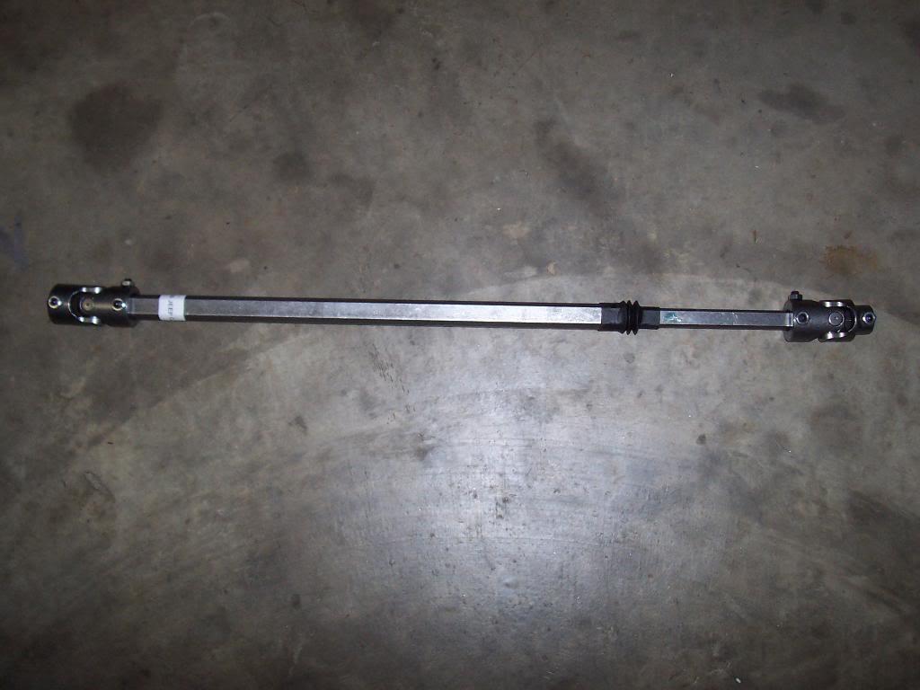
Sliding on the upper joint to the column. Clean, rust free splines plus a little wheel bearing grease makes sliding these two parts together much easier then fighting dry, rusty splines.
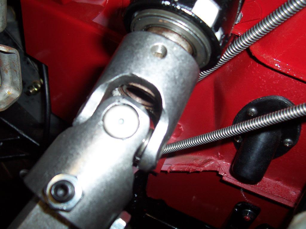
I slid the upper joint on, tightened down the set screw to leave a mark, then slid the assembly back off. You can see the mark the set screw made.
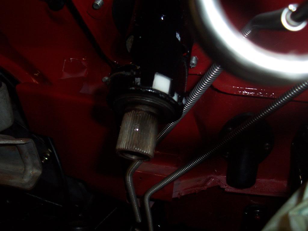
Then used my Dremel with a high speed metal cutter to remove some material where the set screw marked the shaft. I removed just enough material so that the set screw had a slight "pocket" to fit into.
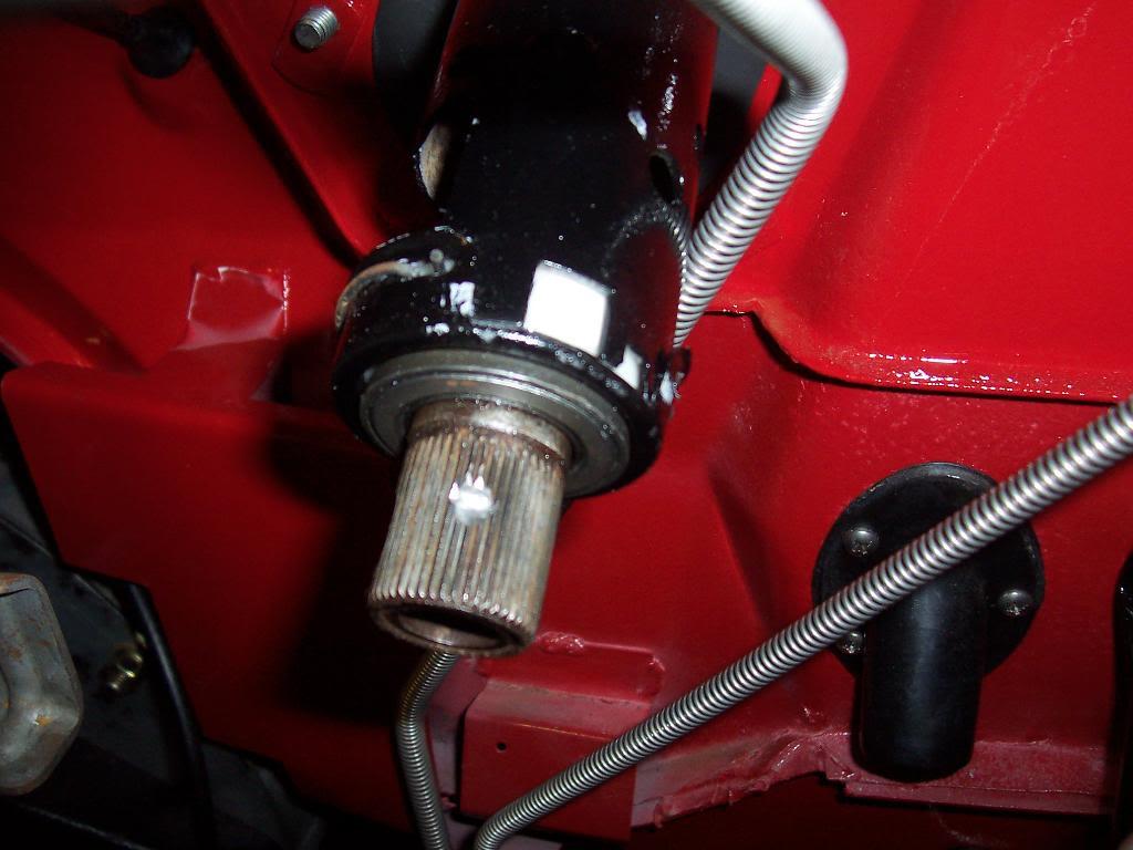
And bolted up the upper shaft to the column.
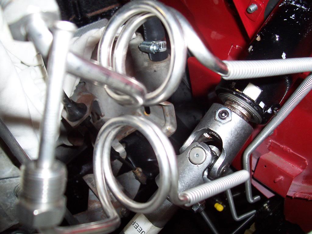
The bottom coupling installation is similar to the top. Slight indentation in shaft for the set screw.
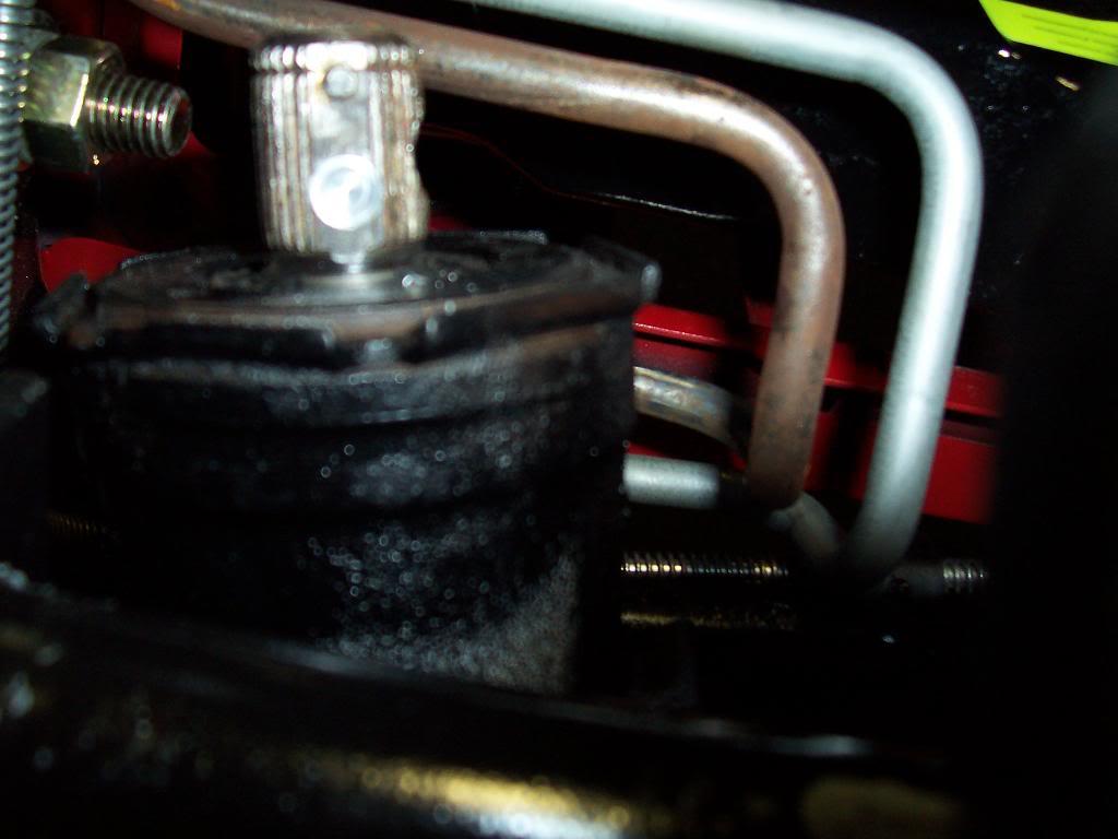
And bolted up. I used Red Locktite on all the fasteners. It is also a good idea to periodically check these setscrews to make sure they are still tight.
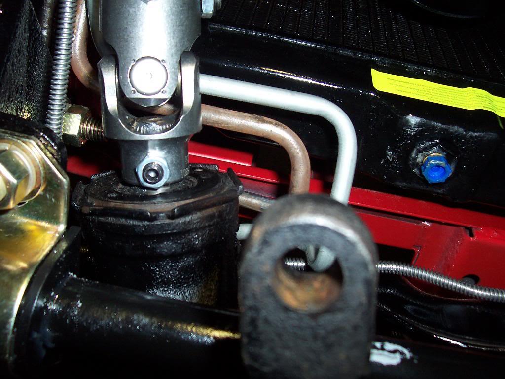
I upgraded from the factory steering shaft to a Borgeson steering shaft. The factory steering shaft is OK for small tires and street use, but I broke a factory steering shaft off road with 33" tires, so I feel that a steering shaft upgrade is a great place to spend money. I have ran a Borgeson shaft for many years on my CJ-7's and have had great luck with them so i bought another one for this Scrambler.
Sliding on the upper joint to the column. Clean, rust free splines plus a little wheel bearing grease makes sliding these two parts together much easier then fighting dry, rusty splines.
I slid the upper joint on, tightened down the set screw to leave a mark, then slid the assembly back off. You can see the mark the set screw made.
Then used my Dremel with a high speed metal cutter to remove some material where the set screw marked the shaft. I removed just enough material so that the set screw had a slight "pocket" to fit into.
And bolted up the upper shaft to the column.
The bottom coupling installation is similar to the top. Slight indentation in shaft for the set screw.
And bolted up. I used Red Locktite on all the fasteners. It is also a good idea to periodically check these setscrews to make sure they are still tight.
Last edited:
- City
- Biloxi
- State
- MS
Rebuilt the clutch tube last night. It is a fairly simple piece, 2 rubber boots, 2 plastic bushings, and 2 clips. I had to drill and tap the tube to accept a new grease fitting since the old Zerk fitting was pretty messed up.
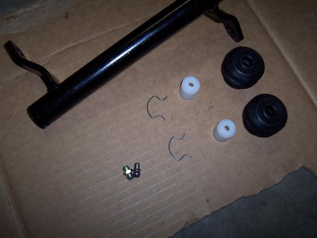
Had to take off the two brackets that hold the tube, one bolts to the body and the other bolts to the bell housing. Slid the rubber boots onto these brackets first. There is a recess present on the shafts where the boot fits on. Bracket to the right has the boot on, bracket to the left does not, you can see the little ridge that the boot fits over.
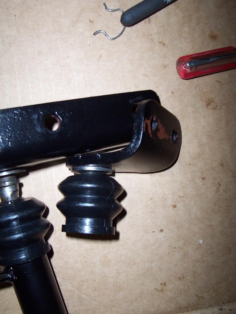
Pushed the plastic bushings onto the two brackets. I greased them up first.
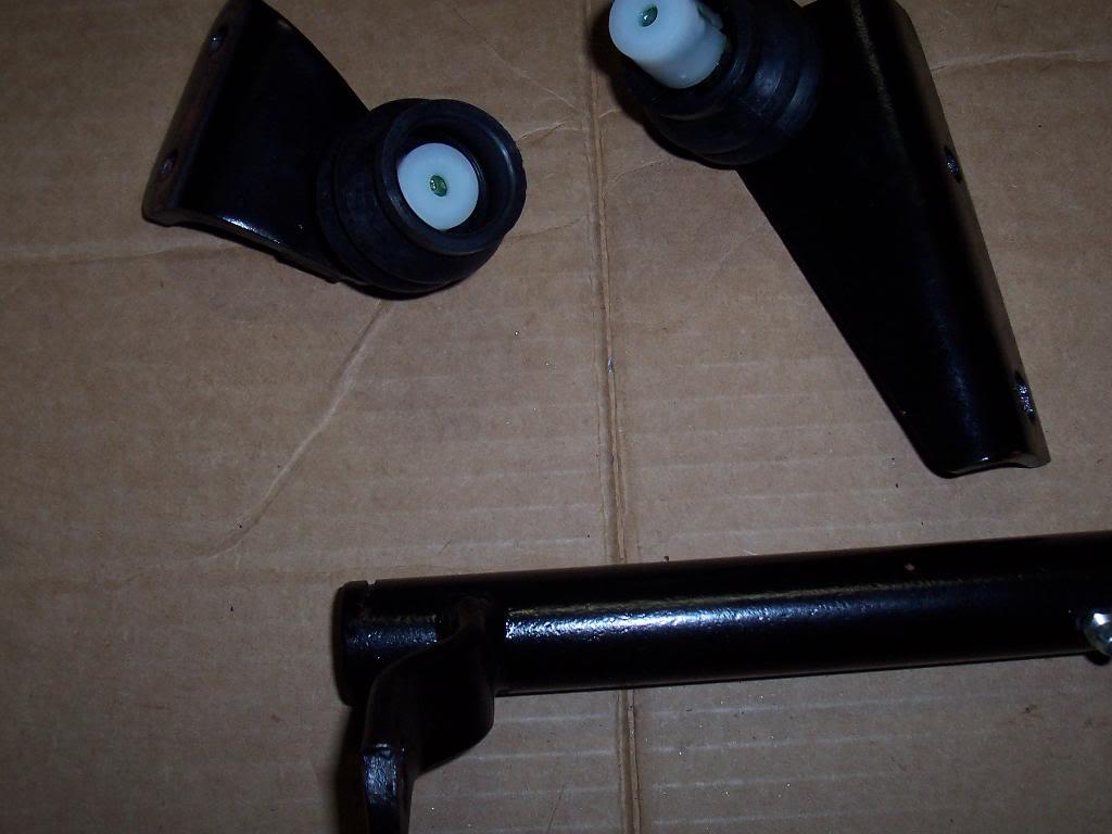
And assembled. I couldn't take a pic, but basically each bracket slides onto the tube, slide the boot back off the tube, insert the metal clips, then slide the boot over the clips, and you are done.
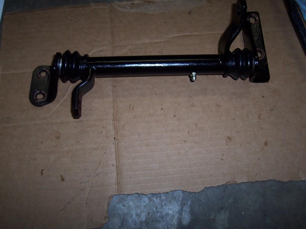
I am going to slightly modify the tube bracket that bolts to the body since the 1" body lift throws it off slightly. The tube and brackets work fine, pivot smooth, unmodified, even with the 1' body lift. But, the tube kind of runs down hill since the body sits 1" higher then stock. I want to keep this piece level, so that it will hopefully stay together better once the frame and body start to flex independently of each other. Just being anal retentive I guess? Once I drop this bracket back level, I don't think the factory bar that runs from the clutch pedal to the cross tube will reach anymore. But, I have a solution to that problem, too.
That's it for now.
Had to take off the two brackets that hold the tube, one bolts to the body and the other bolts to the bell housing. Slid the rubber boots onto these brackets first. There is a recess present on the shafts where the boot fits on. Bracket to the right has the boot on, bracket to the left does not, you can see the little ridge that the boot fits over.
Pushed the plastic bushings onto the two brackets. I greased them up first.
And assembled. I couldn't take a pic, but basically each bracket slides onto the tube, slide the boot back off the tube, insert the metal clips, then slide the boot over the clips, and you are done.
I am going to slightly modify the tube bracket that bolts to the body since the 1" body lift throws it off slightly. The tube and brackets work fine, pivot smooth, unmodified, even with the 1' body lift. But, the tube kind of runs down hill since the body sits 1" higher then stock. I want to keep this piece level, so that it will hopefully stay together better once the frame and body start to flex independently of each other. Just being anal retentive I guess? Once I drop this bracket back level, I don't think the factory bar that runs from the clutch pedal to the cross tube will reach anymore. But, I have a solution to that problem, too.
That's it for now.
Last edited:
- City
- Biloxi
- State
- MS
Small update. Did some clutch linkage work. Just to see if it works, I put the stock clutch linkage pieces on. The stock pieces will work if you leave the tube piece running at the slight angle that results from the 1" body lift.
Picture of where the long piece ties onto the clutch tube crossover piece.
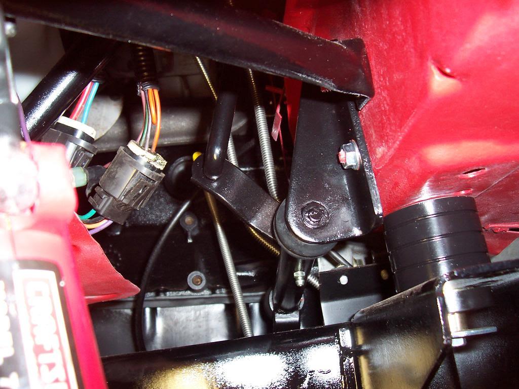
Picture of where the long piece ties onto the clutch pedal assembly under the dash. You can just make out where the bar slides through the pedal, directly underneath the rusty brown colored spring.
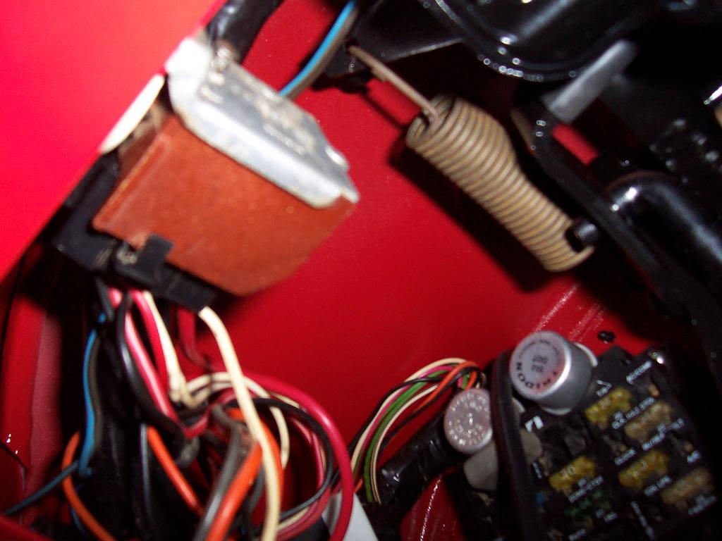
The stock pieces will work with the 1" body lift. The cross over tube running at the slight angle still bugs me, though.
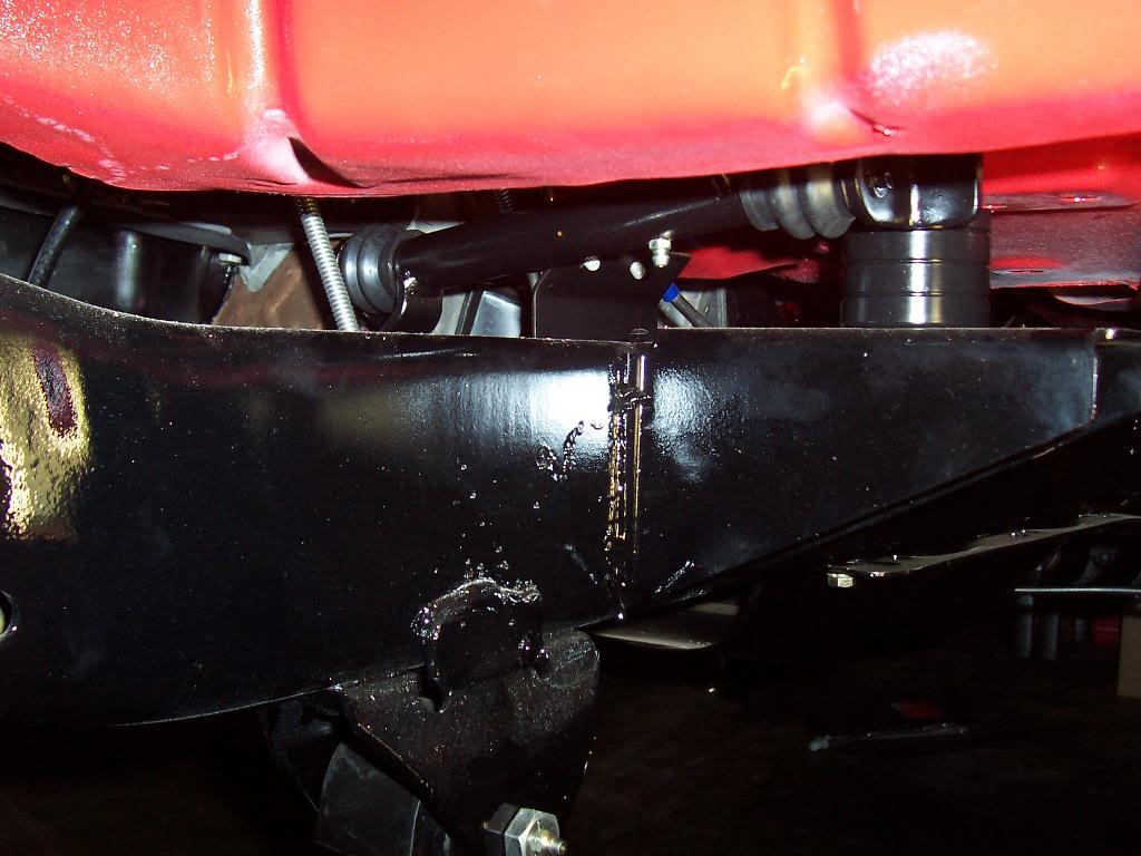
I am going to drill a new hole in the bracket that ties the crossover tube to the body in order to drop it down 1" so that it sits level. By doing this, though, the stock linkage piece that runs from the pedal to the crossover tube will be too short. This is not going to be a problem for me since I ordered a heavy duty clutch linkage kit that works with the body lift. Picture of the heavy duty clutch linkage kit next to the stock clutch linkage pieces.
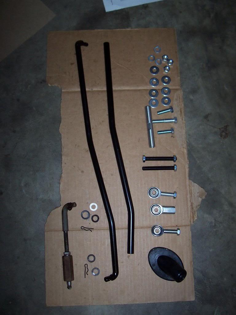
And the heavy duty linkage assembled next to the factory linkage. You can see where I have adjusted the new piece to be 1" longer then stock to make up for the body lift.
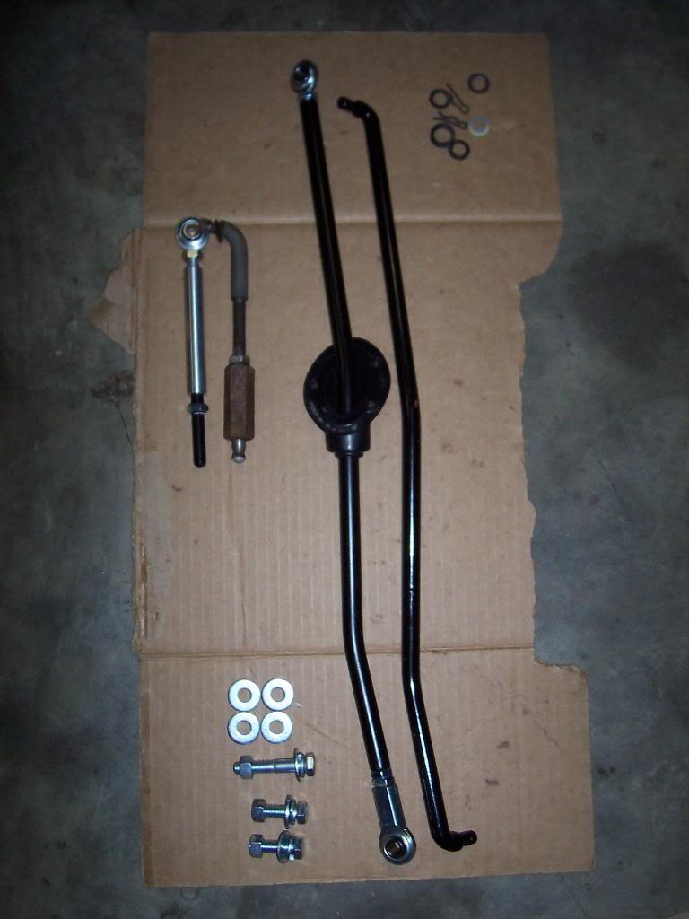
My old brown CJ-7 had this same linkage kit on it and I loved it. It eliminates all the play in the stock linkage, it has a stronger tube piece that runs from the pedal to the crossover tube (I have had the stock linkage piece bend before), and it offers plenty of adjustments. Just make sure you order the correct kit for your jeep, with or without body lift.
That's it for now.
Picture of where the long piece ties onto the clutch tube crossover piece.
Picture of where the long piece ties onto the clutch pedal assembly under the dash. You can just make out where the bar slides through the pedal, directly underneath the rusty brown colored spring.
The stock pieces will work with the 1" body lift. The cross over tube running at the slight angle still bugs me, though.
I am going to drill a new hole in the bracket that ties the crossover tube to the body in order to drop it down 1" so that it sits level. By doing this, though, the stock linkage piece that runs from the pedal to the crossover tube will be too short. This is not going to be a problem for me since I ordered a heavy duty clutch linkage kit that works with the body lift. Picture of the heavy duty clutch linkage kit next to the stock clutch linkage pieces.
And the heavy duty linkage assembled next to the factory linkage. You can see where I have adjusted the new piece to be 1" longer then stock to make up for the body lift.
My old brown CJ-7 had this same linkage kit on it and I loved it. It eliminates all the play in the stock linkage, it has a stronger tube piece that runs from the pedal to the crossover tube (I have had the stock linkage piece bend before), and it offers plenty of adjustments. Just make sure you order the correct kit for your jeep, with or without body lift.
That's it for now.
- City
- Biloxi
- State
- MS
Fixed the leaning clutch crossover tube last night.
Took the tube down and marked a new hole on the bracket that secures it to the firewall, 1" higher then the lower hole.
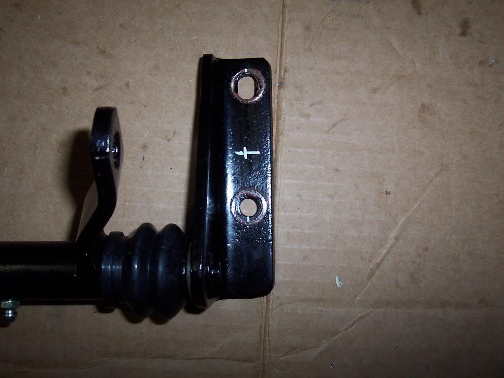
Drilled the new upper mounting hole.
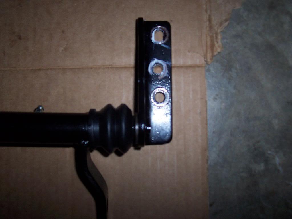
The white line on the body is a straight line mark I made before I took the bracket off. I made this line to ensure that the bracket would be straight once I drilled the new hole. I temporarily bolted on the bracket using only the lower bolt hole so that I could mark the hole I need to drill into the body for the new upper mounting bolt.
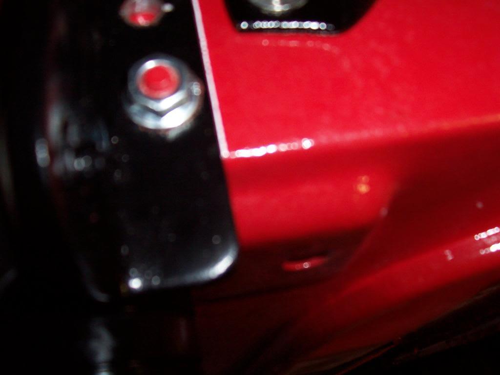
New upper mounting hole marked on the body.
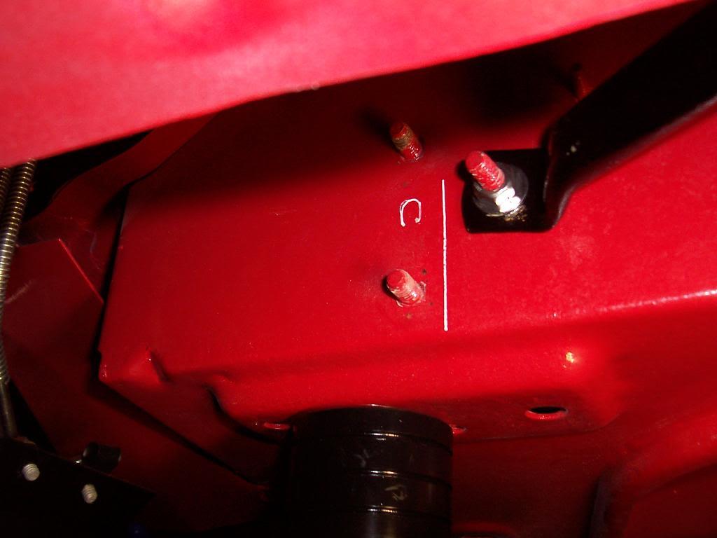
And the new upper mounting hole drilled. I went back and painted the raw metal. I had to remove the coolant overflow bottle and the "brain box" from the fender in order to get a drill down there to drill the hole. An angle drill would have come in handy.
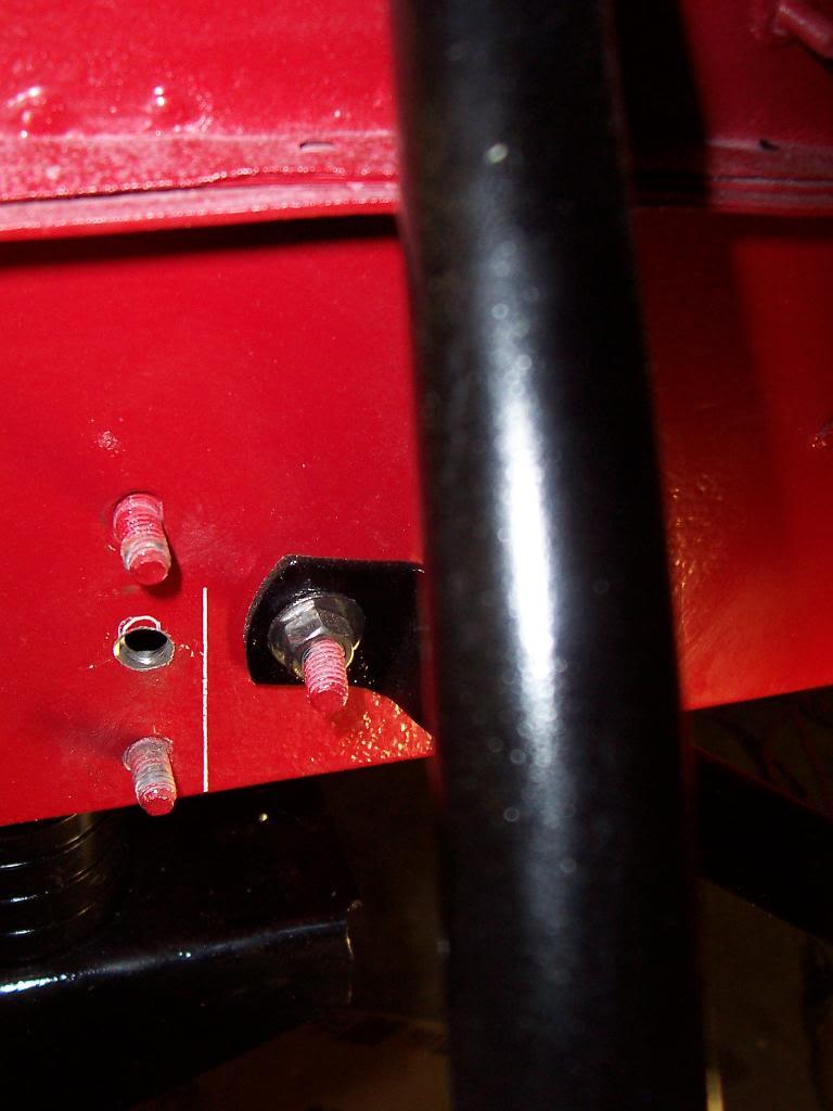
And the clutch linkage crossover tube bolted back up. Still need to touch up the paint on the bracket.
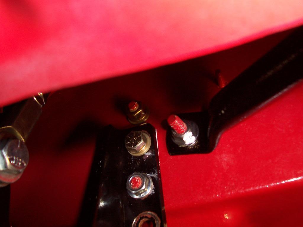
And its level again.
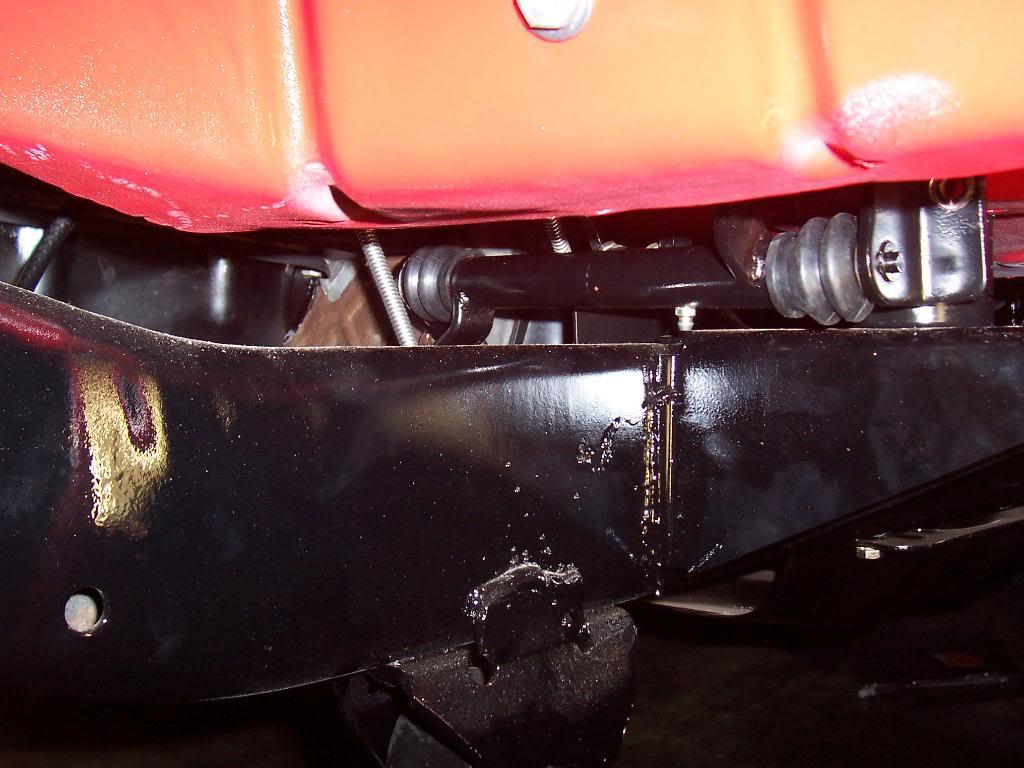
Fairly simple modification to do. If you have a body lift over 1", it would take some more fabrication to get this piece level again.
That's it for now.
Took the tube down and marked a new hole on the bracket that secures it to the firewall, 1" higher then the lower hole.
Drilled the new upper mounting hole.
The white line on the body is a straight line mark I made before I took the bracket off. I made this line to ensure that the bracket would be straight once I drilled the new hole. I temporarily bolted on the bracket using only the lower bolt hole so that I could mark the hole I need to drill into the body for the new upper mounting bolt.
New upper mounting hole marked on the body.
And the new upper mounting hole drilled. I went back and painted the raw metal. I had to remove the coolant overflow bottle and the "brain box" from the fender in order to get a drill down there to drill the hole. An angle drill would have come in handy.
And the clutch linkage crossover tube bolted back up. Still need to touch up the paint on the bracket.
And its level again.
Fairly simple modification to do. If you have a body lift over 1", it would take some more fabrication to get this piece level again.
That's it for now.
- City
- Biloxi
- State
- MS
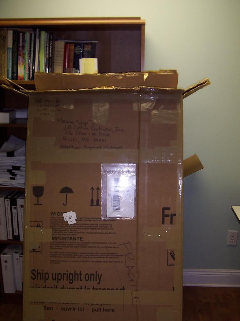
This showed up at work today. Not something I really needed to get my Scrambler running, and it did eat up some of my tire fund, but when it popped up for sale I decided to grab it because these don't come up for sale much.
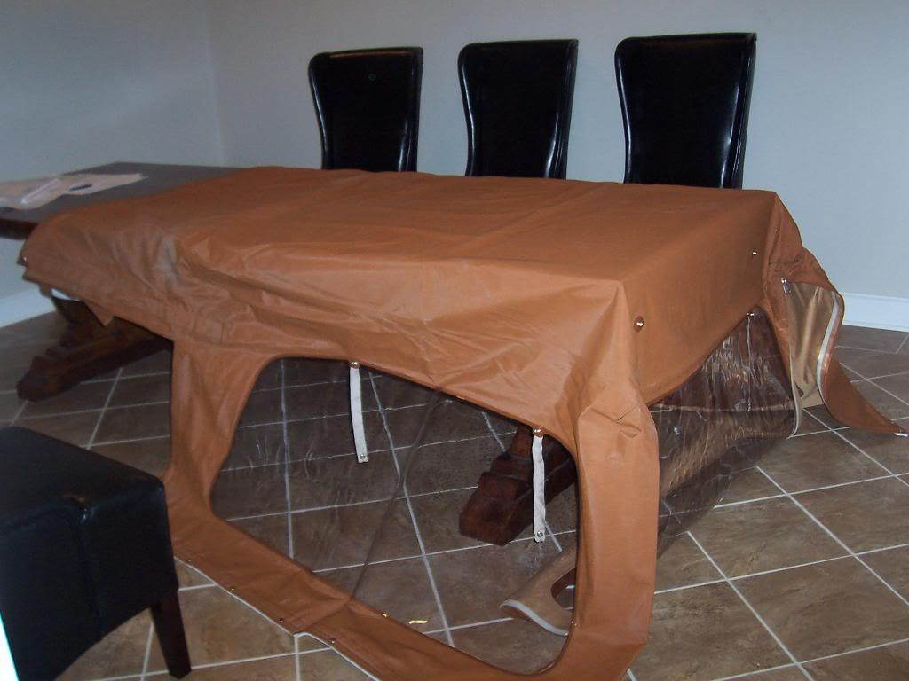
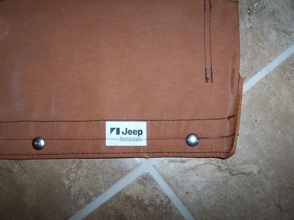
NOS Jeep/Whitco Full soft top. I spread it out on the conference room table, so no conferences for the rest of this week LOL.
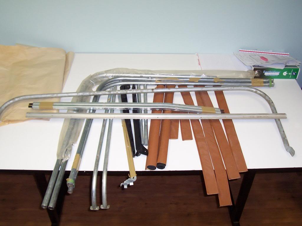
And the rest of the pieces.
I am not sure if i am going to install this top or the NOS Jeep/Whitco 1/2 soft top that I have.
NOS Jeep/Whitco Full soft top. I spread it out on the conference room table, so no conferences for the rest of this week LOL.
And the rest of the pieces.
I am not sure if i am going to install this top or the NOS Jeep/Whitco 1/2 soft top that I have.
Last edited:

 but isn't this supposed to be your WHEELIN Jeep??

Bushmaster6
Legacy Registered User
- City
- the Springs
- State
- CO
dammmn.. is that the one you beat me to the punch on a few weeks ago?
edit: just saw your Kayakgreen endorsement..
me want
edit: just saw your Kayakgreen endorsement..
me want

 Wheel it outside for a pic too (if it's mobile)....