• Notice for iPhone users: DO NOT use the image size reduction option when uploading photos to the forum. This causes portrait images to post as landscape. We have added a warning to the image insert pop-up as well.
Another Scrambler Purchase/Road Trip - UPDATE- BODY ON FRAME AGAIN

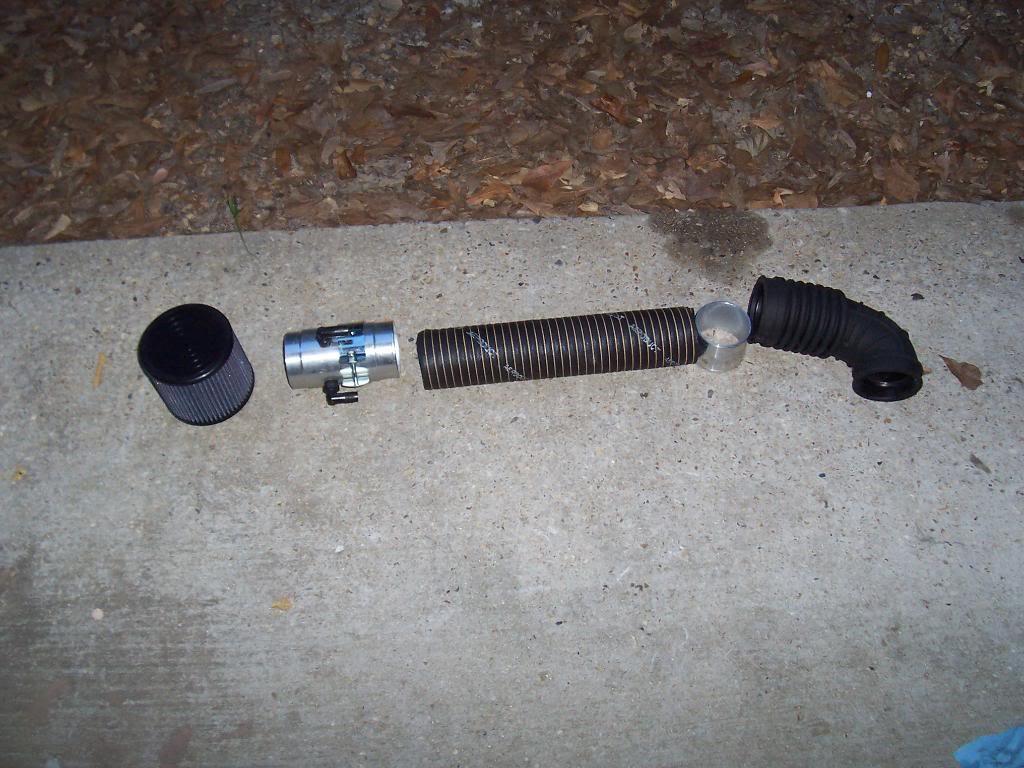
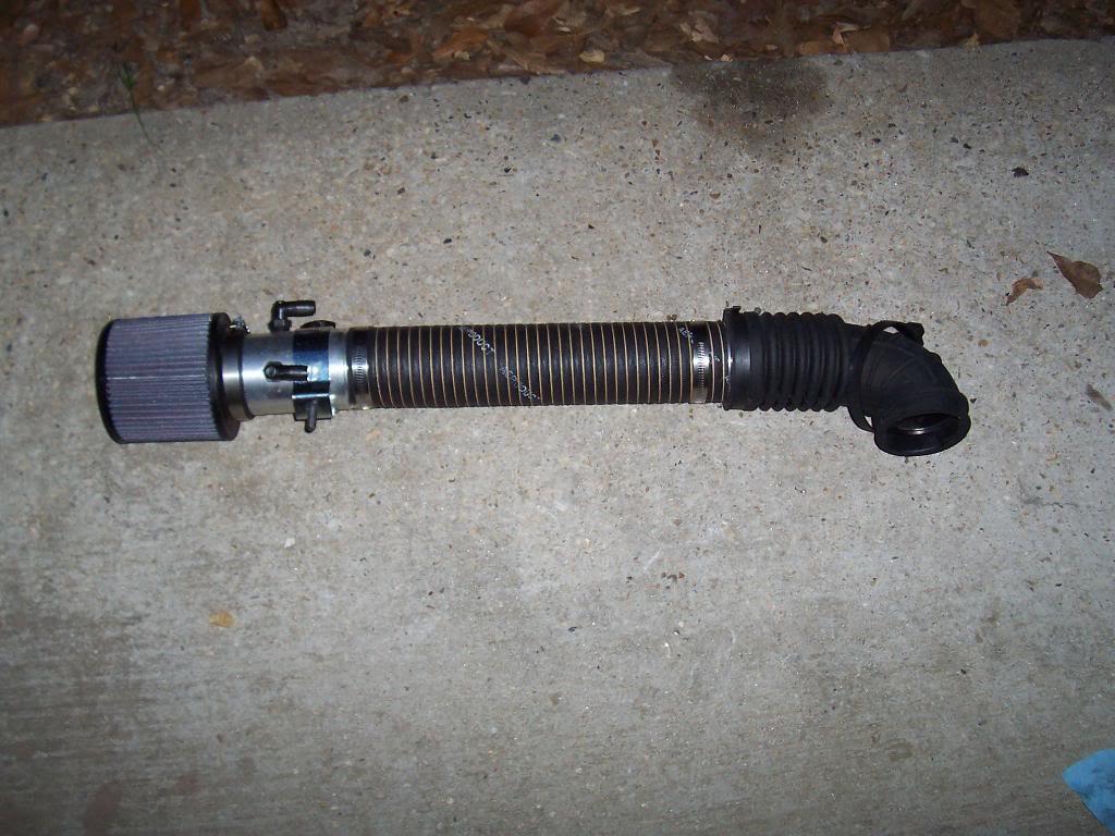
More "easy" stuff. Assembled the air intake/cleaner assembly. I mainly did this just to get rid of loose parts that are just laying around. I might update the hose that connect the air filter to the intake elbow in the future.

0118-1.jpg


0127-1.jpg


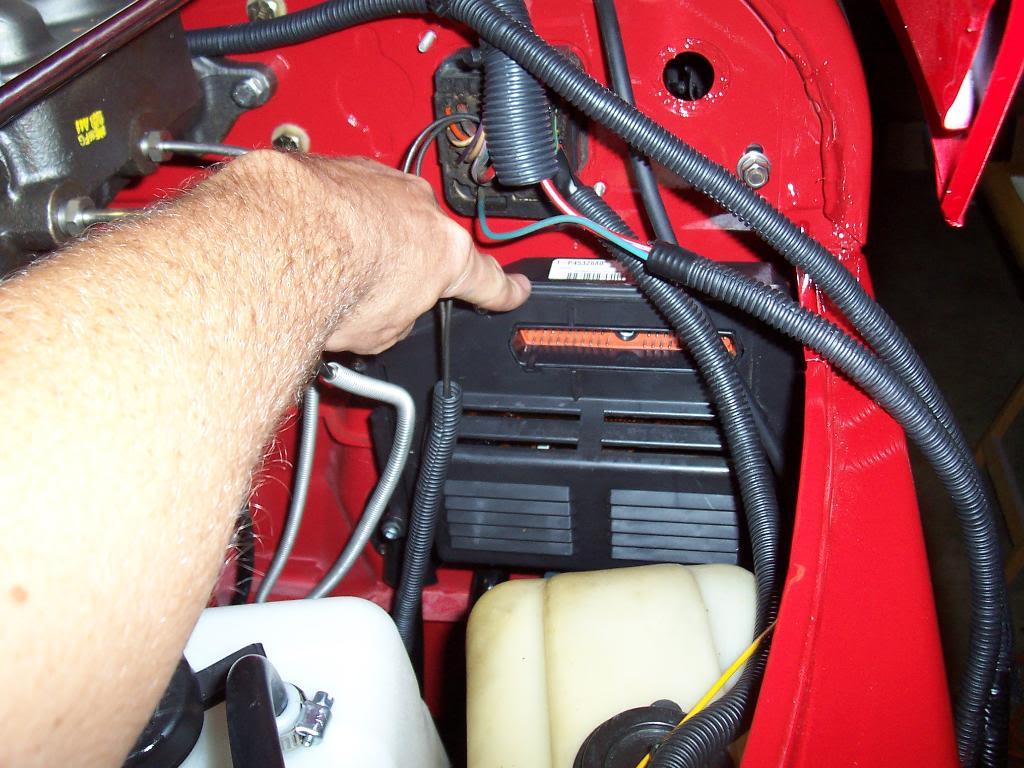
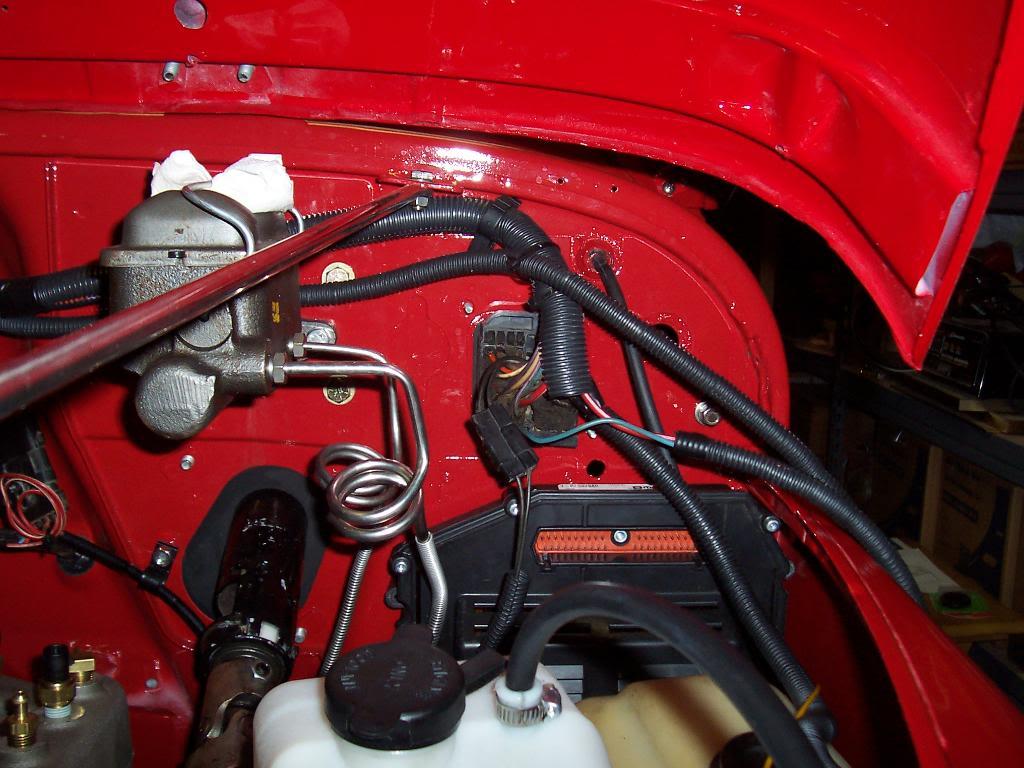
Figured this is the best place to mount the new computer. It fits well here and the new harness should easily reach this location. I wont screw it to the fire wall until I am sure the harness will reach, but it should.

0136-1.jpg


0146-1.jpg


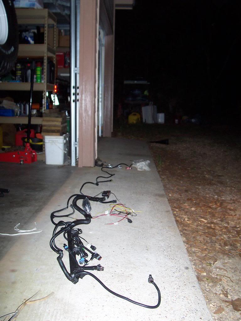
This will be the next step: the new harness. It is a nice piece. All the connections are labeled and pre terminated. It shouldn't take too long to get this hooked up.

0155-1.jpg


Crank position sensor/fuel injectors/ intake manifold sensors.

0165-1.jpg


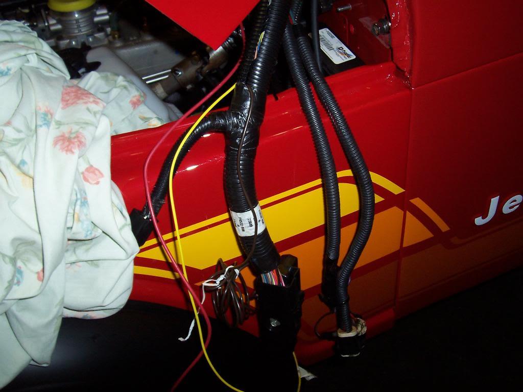
60 pin computer harness connector/relays/ and the wires used to connect this new harness to the factory harness (3 or 4 loose wires).

0174-1.jpg


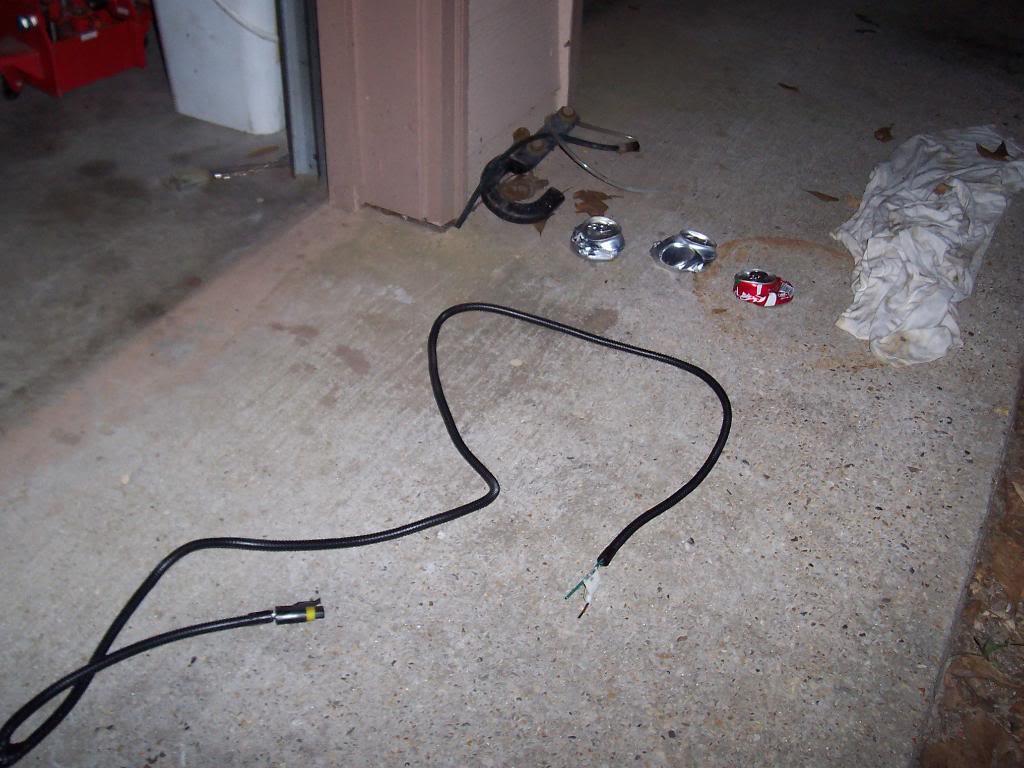
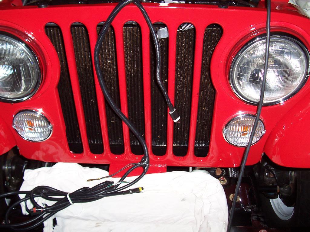
Vehicle speed sensor connection and the fuel pump wires. I wonder if the last part will be long enough to fit a Scrambler without lengthening them???

0184-1.jpg


That's it for now.
 
Last edited:
Got most of the wiring harness installed.

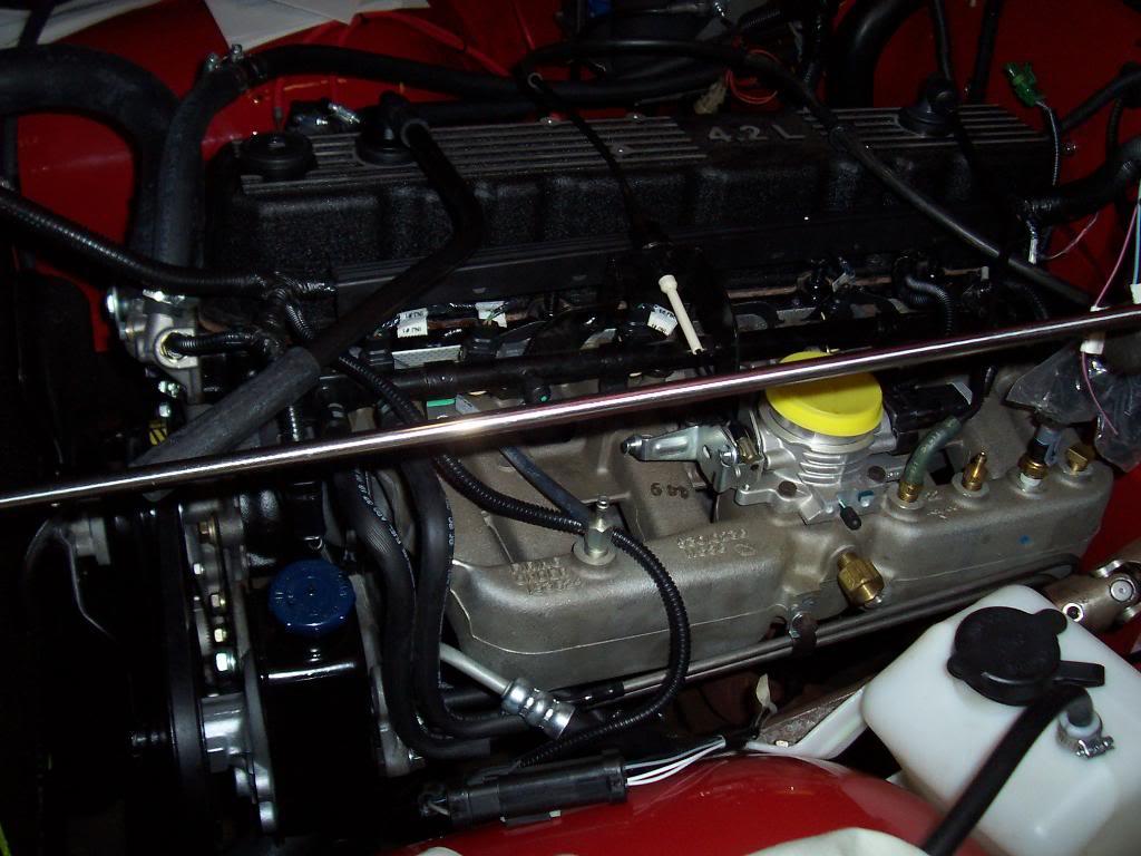
Installed the driver side part first. This consists of the injector wires, front of engine wires, and intake manifold wires. The long black plastic thing snaps onto 3 of the head studs that stick up.

00126-1.jpg


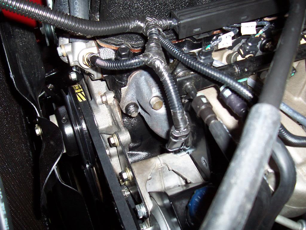
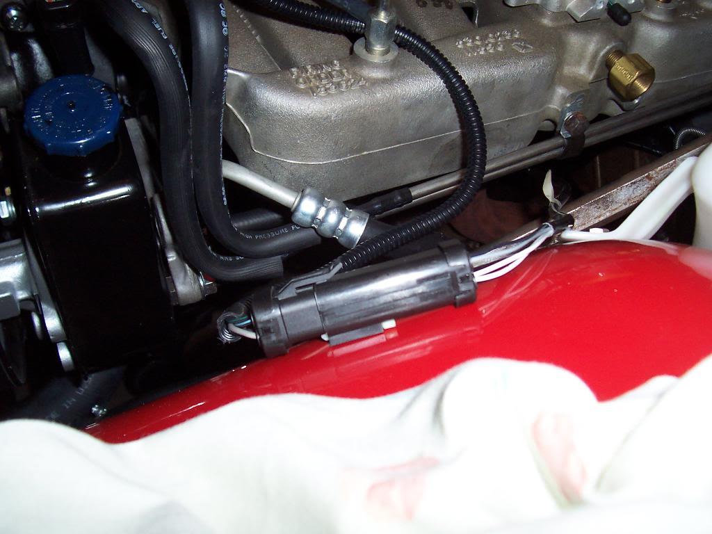
Picture of the coolant temperature sensor, on the thermostat housing, and the wire dropping down to the crank position sensor, running behind the aluminum power steering pump bracket.

00227-1.jpg


Another up front wire, the O2 sensor connector. I mounted this sensor on the driver side inner fender.

00323-1.jpg


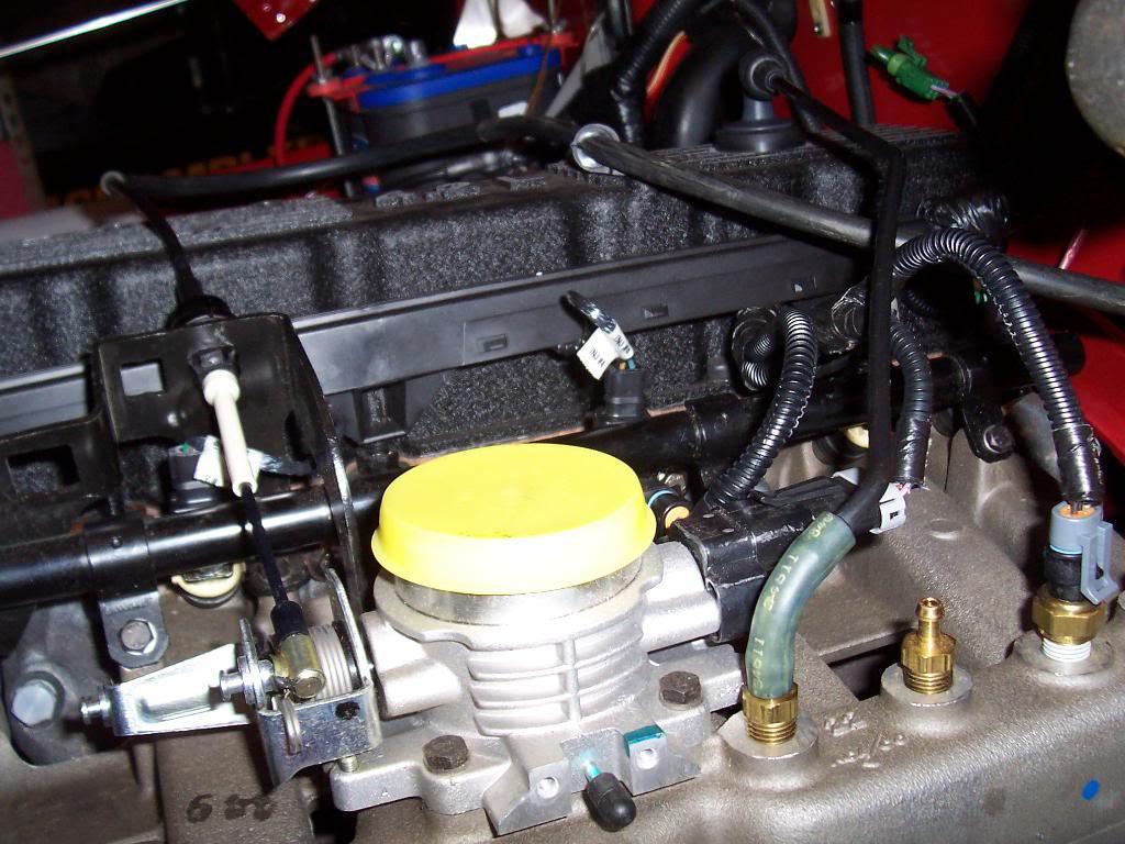
Close up of the 3 intake manifold sensor connectors. Two of the three are directly on the throttle body and the other goes on the manifold, third brass plug thing.

00424-1.jpg


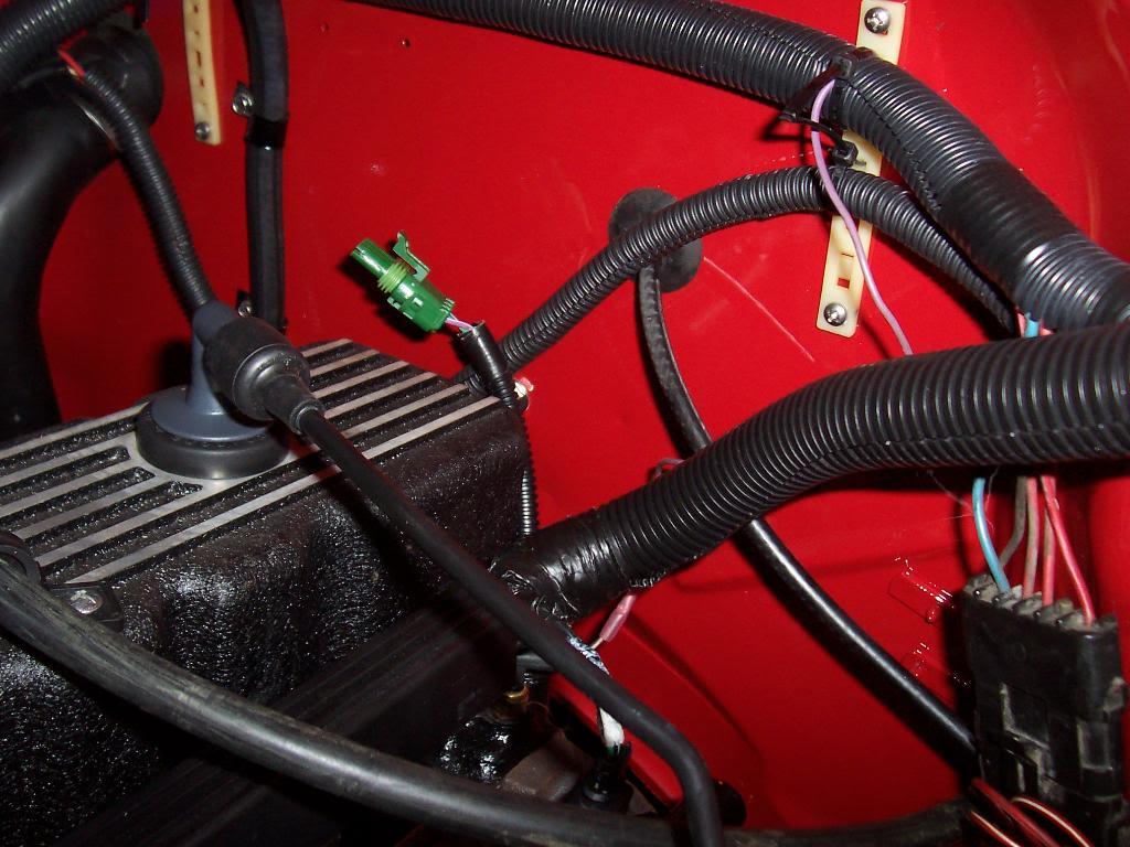
The green plug, behind the motor sticking up, is for the MAP sensor, which hasn't been mounted at this point.

00522-1.jpg


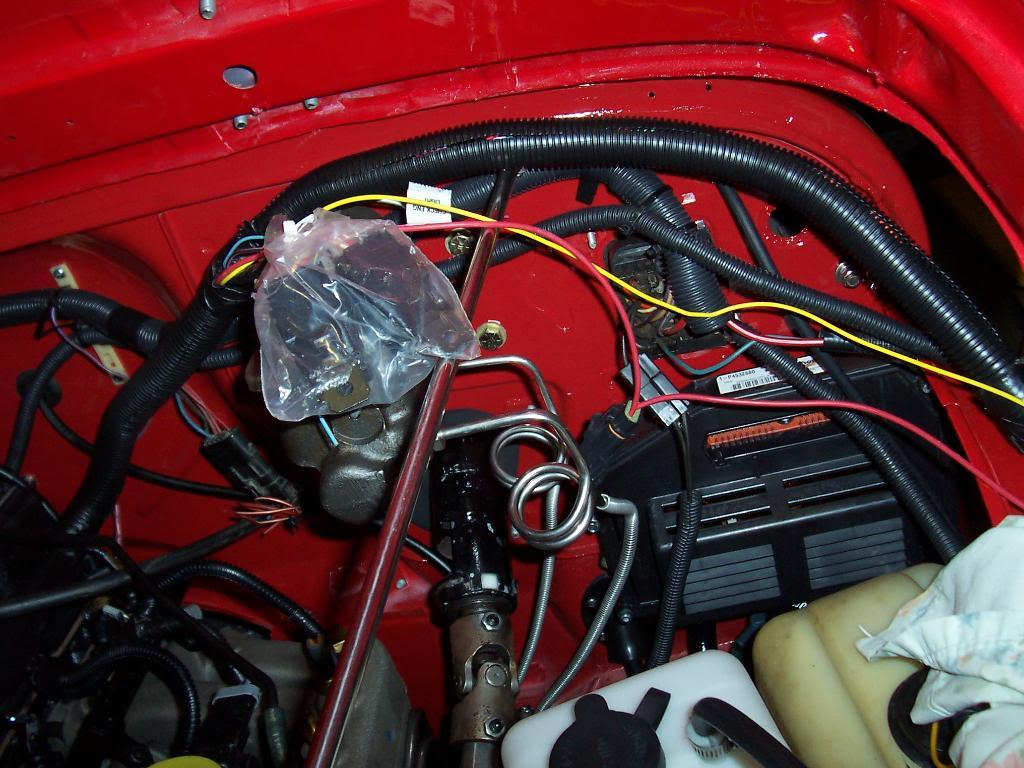
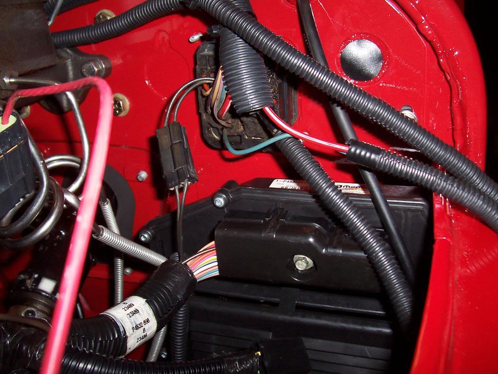
The harness then goes to the fire wall and up and over the master cylinder to the computer. The plastic bag in the picture contains two relays that are connected to the harness.

00616-1.jpg


This picture is showing this end of the harness. You can see the big 60 pin connector that plugs into the computer. The loose yellow, red, and brown wires tie into the factory harness to provide power. The two loose pig tails at the far right of the picture went to the factory ignition control box that was mounted on the inner driver side fender. They will be removed in the near future.

00715-1.jpg


Plugged in the 60 pin connector to the computer.

00913-1.jpg


Mounted the MAP sensor (green plug) to the firewall and plugged it into the harness. I mounted it at this location because there was an existing unused hole in the firewall here.

01011-1.jpg


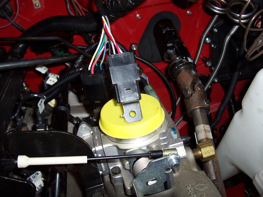
Picture of the two relays (directly above the yellow plastic cover). These need to be mounted to the firewall. I am not going to mount them until I straighten out the harness.

0119-1.jpg
 
Now for the passenger side of the engine harness, much simpler.

Picture of the remaining harness. It runs around the front of the valve cover to the passenger side.

00814-1.jpg


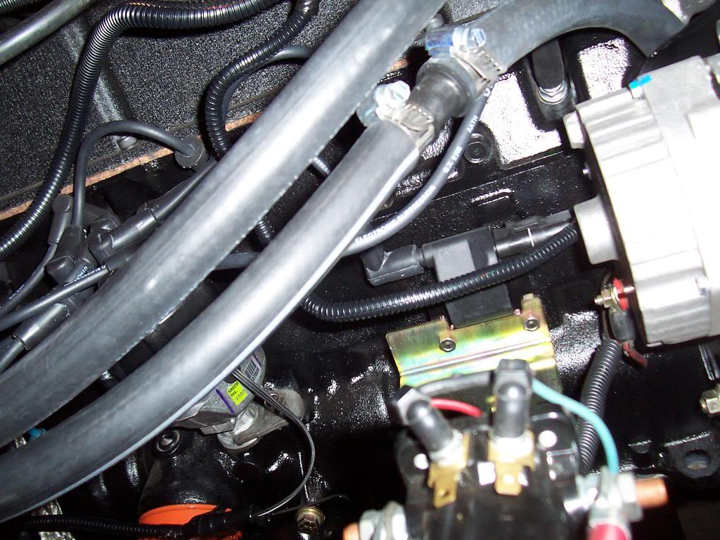
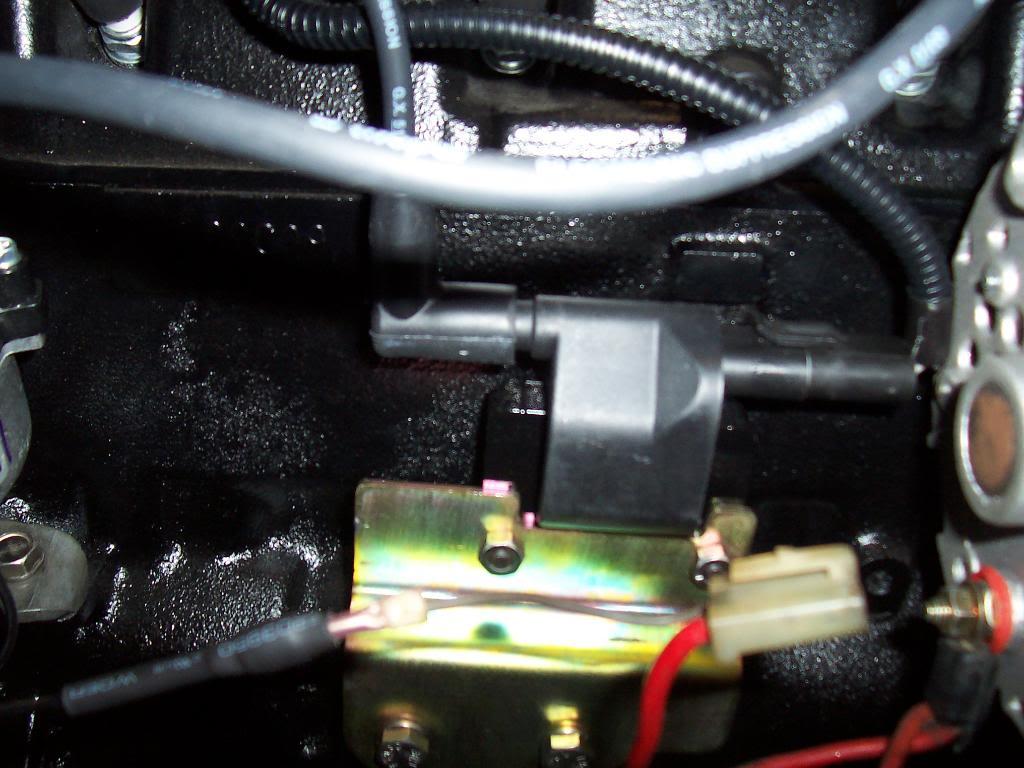
The first connector plugs into the coil, which is directly behind the alternator.

0128-1.jpg


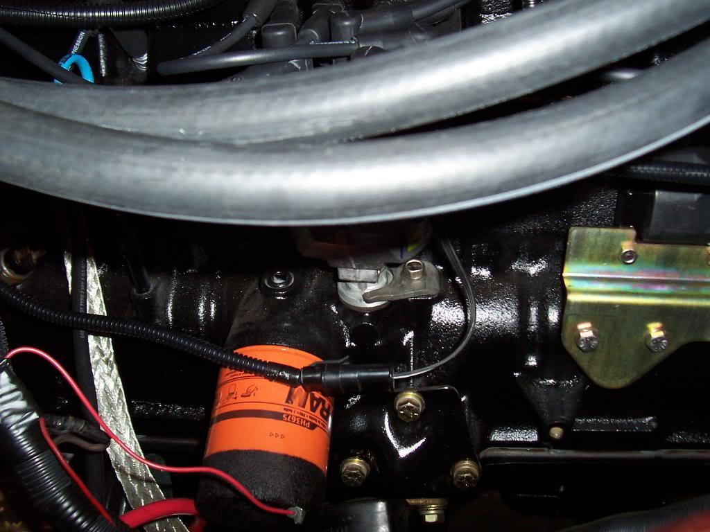
The second connector plugs into the distributor, the connector is directly above the orange oil filter.

0137-1.jpg


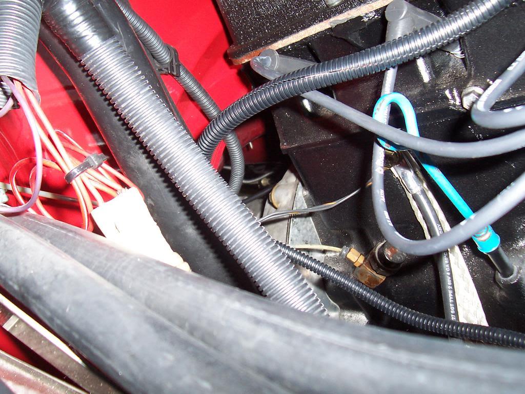
The third wire is a ground strap for the harness. I bolted this strap to the block with the same bolt that holds the battery to engine block ground wire and the block to frame ground strap. This bolt is directly behind and to the rear of the dipstick tube. You can see the bright silver ground strap that runs to the frame.

0147-1.jpg


The rest of this harness then runs under the body. The next connector plugs to the vehicle speed sensor (mounts where the speedometer cable attaches to the transfer case). From this point the harness runs to the rear of the jeep to connect to the fuel pump. I have not ran this part of the harness yet.

That's it for now.
 
Picture of the coolant temperature sensor, on the thermostat housing, and the wire dropping down to the crank position sensor, running behind the aluminum power steering pump bracket.

00227-1.jpg

that plug is awful close to the exhaust manifold. I routed mine over the intake manifold and around the power steering pump.
 
that plug is awful close to the exhaust manifold. I routed mine over the intake manifold and around the power steering pump.

I will take a look at it again and reroute if necessary, thanks for the heads up:cheers:

I still have a bunch of rerouting and wire tying to do:crazy:
 
no worries. I melted the split loom on some of my harness and it was alot father away that that!!

looks great!
 
Finished up the Mopar MPI install this weekend.

Connected the vehicle speed sensor to the speedometer hook up on the Dana 300 and attached the speedometer cable to the sensor.

00127-1.jpg


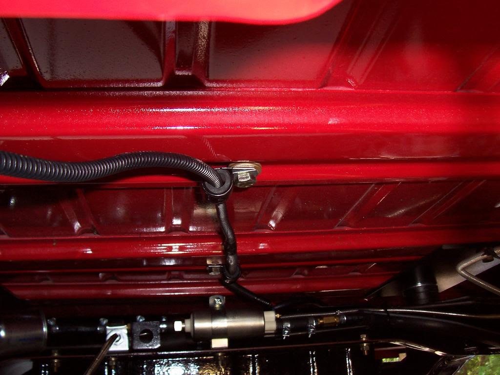
Reconnected my fuel feed line to the tank and routed it back along the cross member, just like factory.

00228-1.jpg


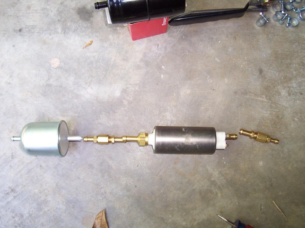
First problem that I ran into: The jeep steel fuel lines are 5/16, the kit supplied fuel filter "IN" side has a 3/8" fitting. I bought another filter that was rated for fuel injection that had 5/16" fitting on each side. Kit filter is black, replacement is silver.

00324-1.jpg


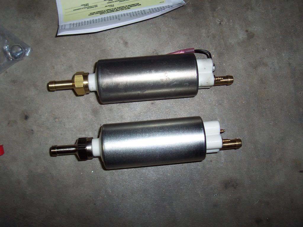
Next problem: The kit supplied fuel pump has 3/8" fittings on both the "IN" and "OUT" sides. Another funny thing, the kit supplied filter has a 3/8" "IN" fitting and a 5/16" "OUT" fitting. Even the kit supplied filter would not hook up to the kit supplied pump!!!!!!!!! My solution: I went to NAPA and bought some high pressure adapter pieces. Each adapter is made up of 3 parts: the center block, a 5/16" fitting, and a 3/8" fitting. Not a cheap way to make this stuff work, probably around $50 in adapters, but I could not think of a better way to adapt the Jeep's 5/16" steel lines to the kit supplied hardware that has 3/8" fittings. The picture explains better:

5/16 jeep steel line to the 5/16 "IN" side of the fuel filter
5/16 "OUT" side of fuel filter to the 5/16" side of one of my adapters
3/8" end of the adapter to the 3/8" "IN" side of the pump
3/8" "OUT" side of the pump to the 3/8" side of on of my adapters
5/16" side of one of my adapters to the factory steel 5/16" line

00425-1.jpg


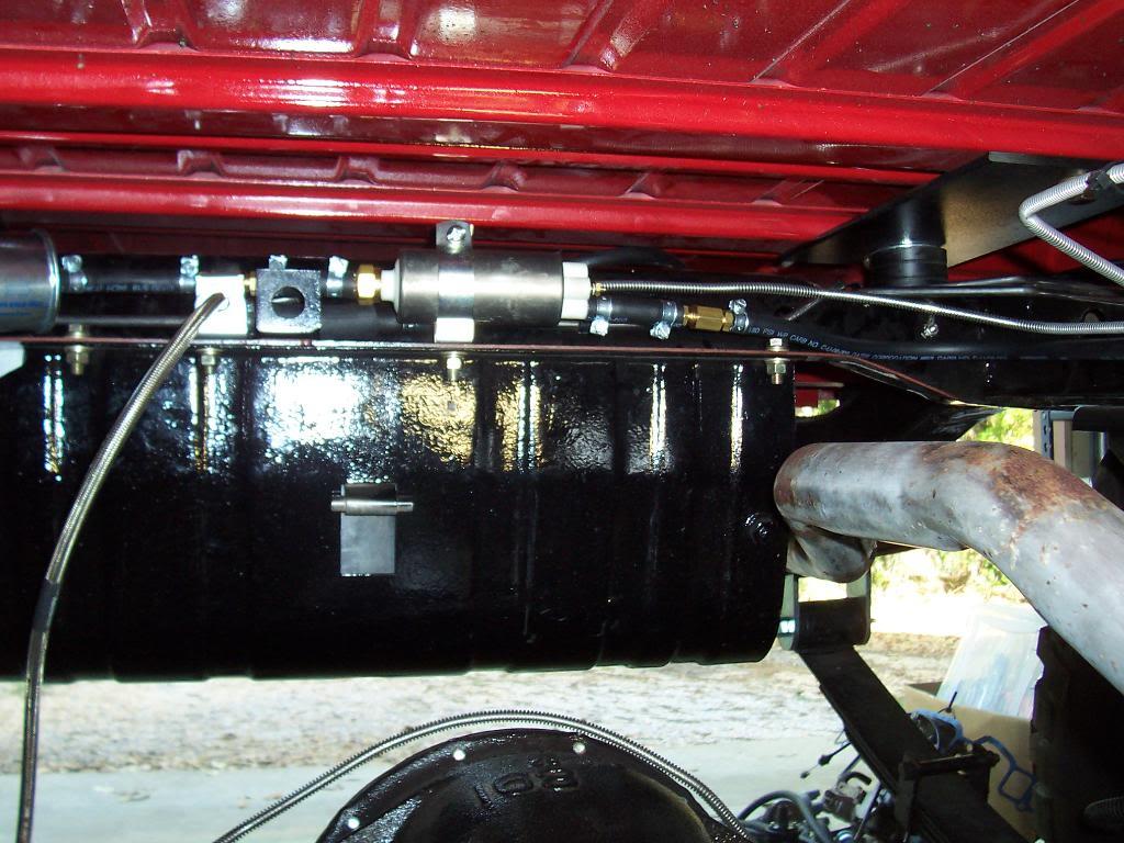
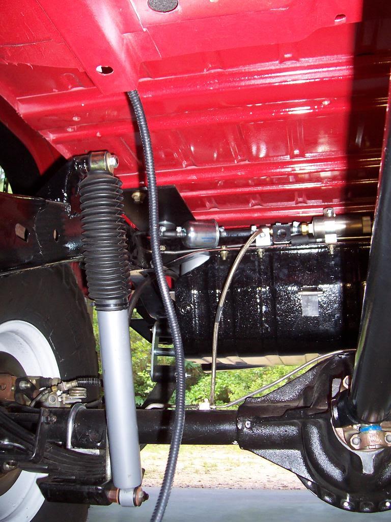
Installed fuel filter/adapter/pump assembly.

00523-1.jpg


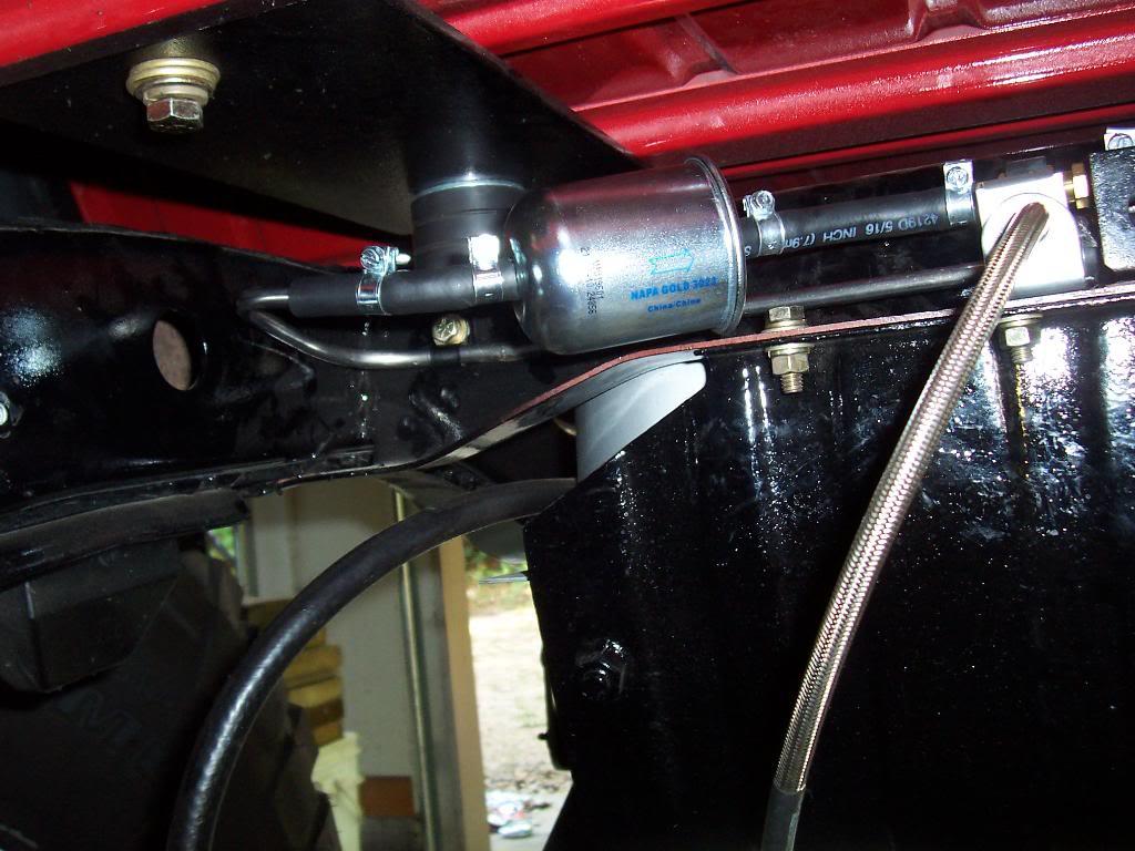
Close up of the filter side.

00617-1.jpg


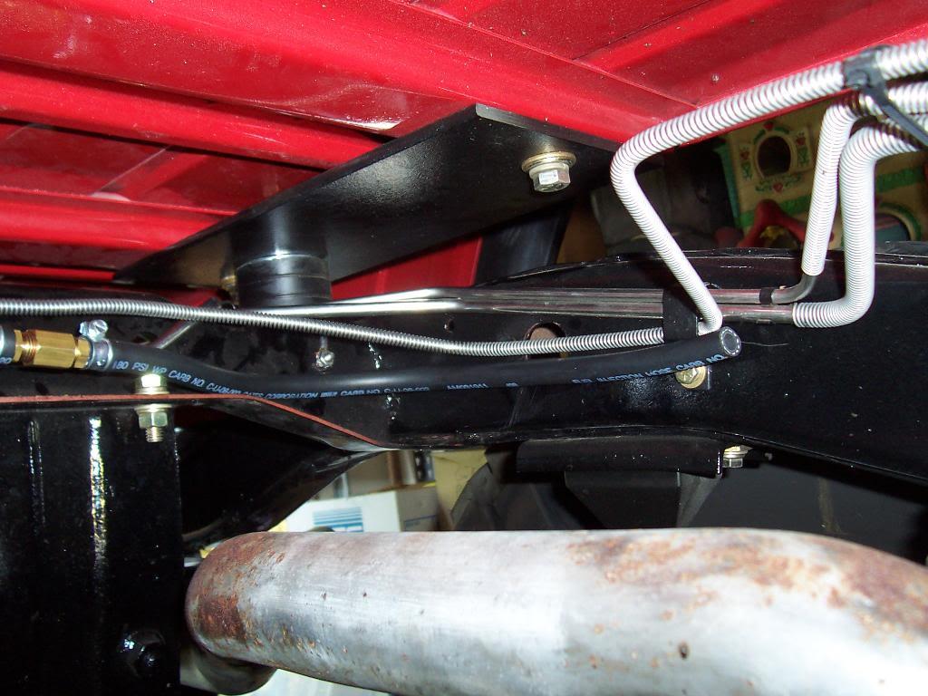
Close up of the out hose, the hose that will tie on to my relocated fuel feed line.

00716-1.jpg


Hooked up the rubber hose coming out of the tank to the relocated steel fuel feed line. I removed the factory fuel feed line from the passenger side and mounted it on the driver side so it would be a straight run into the intake manifold. The thicker rubber hose is mounted over the actual fuel hose to prevent the fuel line from being cut from rubbing against metal. I sheathed all my rubber fuel line inside a larger piece of rubber hose to prevent chaffing.

00815-1.jpg


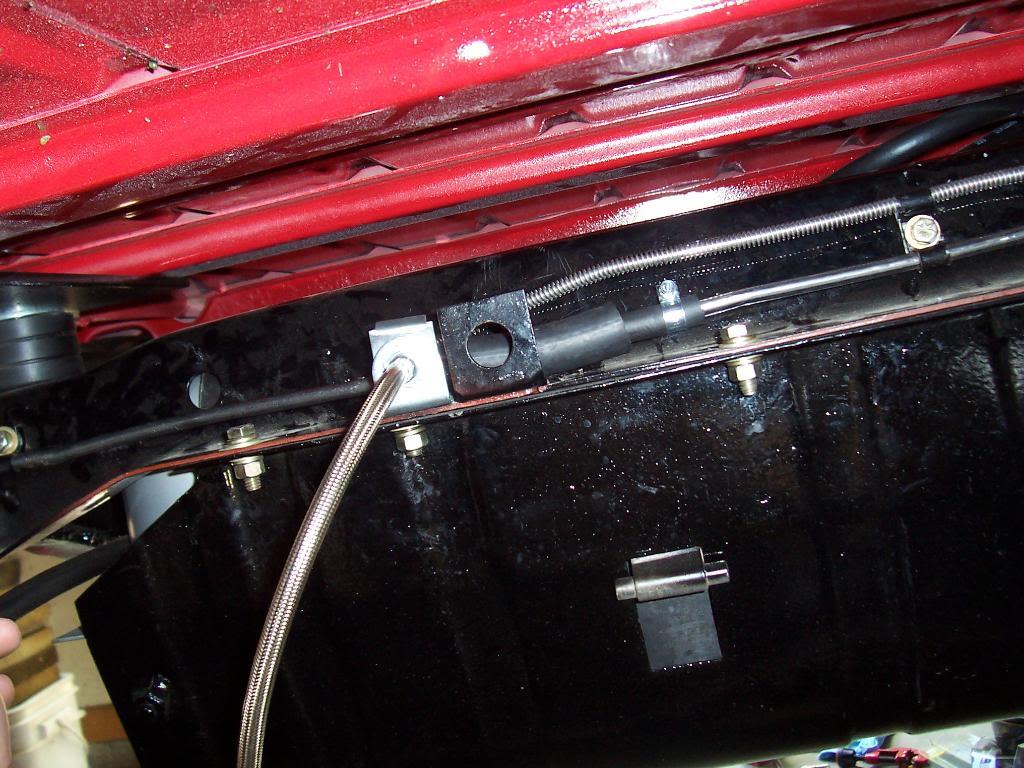
Some pictures of how I routed my new driver side fuel feed line. I drilled a hole through the steel bracket that the parking brake line hooks to so that my new fuel feed line could run through it without any bends. I inserted a rubber grommet in the hole to prevent the metal fuel line from getting cut.

00914-1.jpg


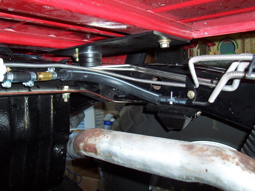
The line passes through the hole in the bracket and runs straight along the frame rail until right before the proportioning valve. From there the a short piece of rubber line connects the frame mounted fuel feed line to the fuel feed line on the intake manifold. The line is secured to the frame with the factory holding clamps that I removed off of the passenger side frame rail. I only had to drill and tap one additional hole in the frame. This did take some work to route this line down the driver side, but this routing makes the most sense to me. The exhaust looks like it is close in the pictures, but i have a minimum of 4" of clearance between any exhaust system part and the fuel lines. Hopefully I will not have any vapor lock issues.

01012-1.jpg
 
Last edited:
Connected my fuel feed and fuel return lines. I used short pieces of fuel injection hose to connect the two frame mounted steel fuel lines to the two intake manifold mounted steel lines to allow for flexing. Picture form the bottom looking up. You can see my extra "anti-chaffing" hose.

01110-1.jpg


Another picture of the same area. You can see the two kit supplied stainless steel fuel lines that are clamped onto the side of the intake manifold, per the instructions.

0129-1.jpg


To me, the hardest part of the installation was mounting the fuel pump and running the new fuel feed line on the drivers side. Everything else was a piece of cake.


Next I installed the kit supplies 7.5 amp diode into the field wire on the alternator. This diode is to help protect the computer, I think it prevent electrical surges from the alternator some how going through the wiring harness and harming the computer. The pink end of the diode goes toward the alternator.

0138-1.jpg


Finished running the wiring harness to the fuel pump. The kit supplied harness was too short, I had to lengthen it by about 10". I guess the Mopar engineers don't have any love for Scrambler owners??????? Ran the harness through a body channel.

0148-1.jpg


The other end of the harness, where it dumps out of the body channel.

0166-1.jpg


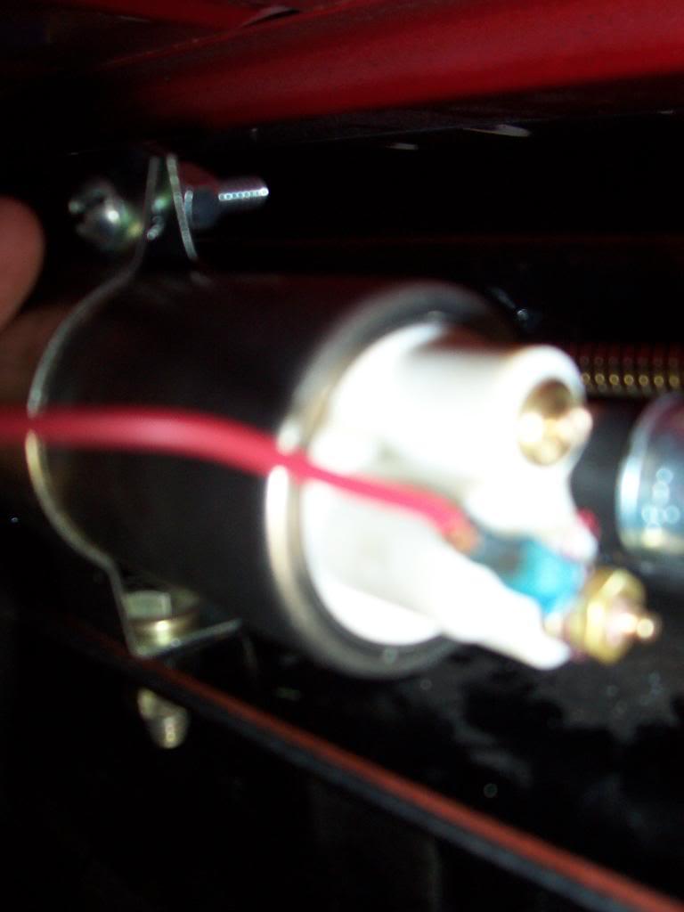
My next problem, not a kit problem. I went to hook up the wires on the fuel pump and one of the brass connectors broke in half.

0175-1.jpg


It had enough thread to wrap bare wire around the post and put the nut on one turn.

0205-1.jpg


I then soldered the wire and nut to the post.

0215-1.jpg


Well, I guess the heat from the soldering damaged the sonic welding glue used to hold the brass post into the plastic housing. The brass post popped out. I tapped it back in with a hammer. I hooked up the pump to another jeep to test it and it leaked fuel out of the damaged post. So I guess a WARNING, if the post pops out and you drive it back in it WILL LEAK. I bought another pump from Auto Zone. It looks identical to the Hesco pump but it has higher pressure and gps ratings.

0223-1.jpg


And after my fuel pump fiasco, hooked up the new fuel pump. You can see in the picture how I ran the wiring harness to the pump.

0232-1.jpg
 
Last edited:
Almost done. The next thing I did was to tie the Mopar MPI wire harness to the factory Jeep chassis wire harness. I had 3 wires to hook up, really easy.

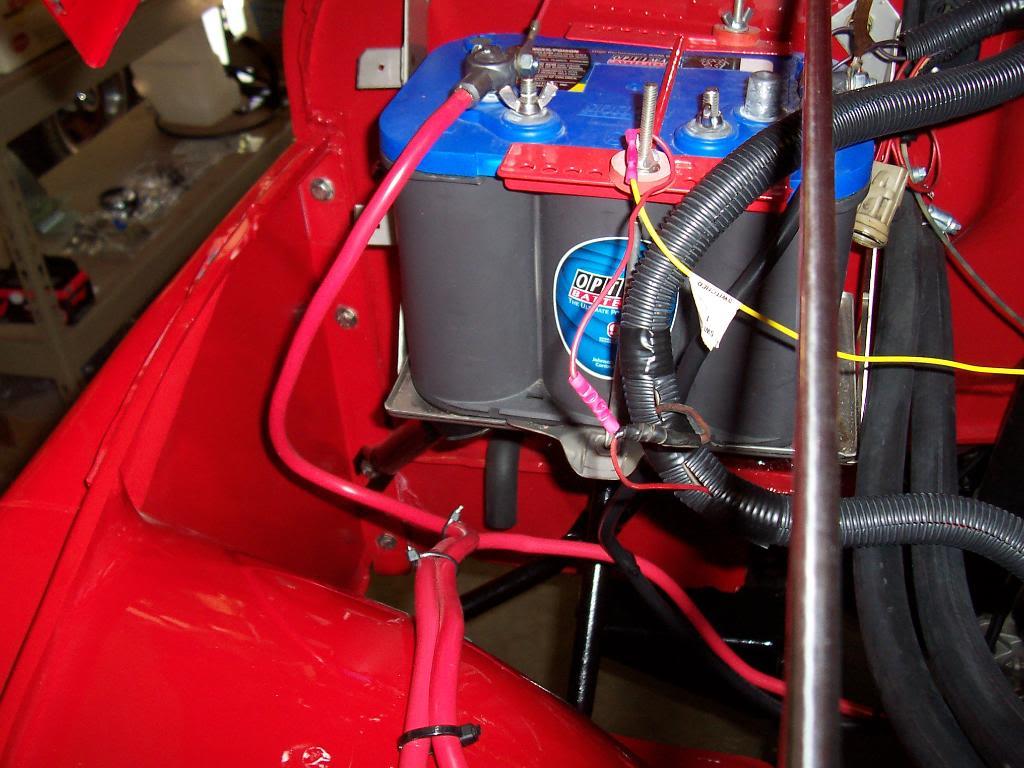
1) The red "12 V battery/power wire - connected this Mopar harness wire directly to the positive battery post. You could also hook it up to the battery side of the starter solenoid, too.

2) The yellow "12 V run/start wire" - This wire needs to be connected to a chassis wire that provides a full 12 volts at "Start" and "Run". I hooked this wire up to the old POSITIVE side ignition coil wire, after confirming it provided the correct voltage with a multi meter.

3) The Mopar harness ground wire - I previously grounded this wire to the engine block with the same bolt that holds the negative battery cable to the engine block.

Quick picture showing the red and yellow Mopar wires. I kind of hooked them up "fast and dirty", I still need to go back up and clean up my under hood wiring.

0262-1.jpg


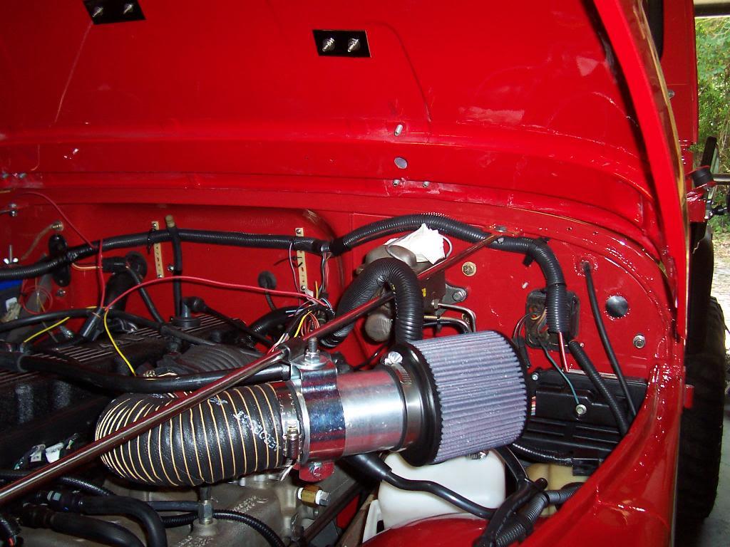
And finally, I installed the air cleaner assembly and the remaining vacuum/emission hoses.

0272-1.jpg


Finally finished. I cycled the key on/off 3 times/ pushed in the Schrader valve on the fuel rail to bleed out the air. I repeated this procedure a few times until gas was spraying out the Schrader valve. I then tried to start the jeep. It fired up, ran a few seconds and died. Started it again, it ran a little bit longer, then died. Repeated this about 3 more times. On the 6th start it fired right up and ran perfect. I think the reason it did not start immediately was because i did not bleed all of the air out of the fuel lines.

Now that I am finished with the install of this kit and have drove the Scrambler a couple of hours with the MPI installed I will make a few comments:

1) OMG, my red Scrambler is bad a$$ fun to drive now. I would say this kit easily bumped the HP up by at least 60.

2) The throttle response is incredible. Besides the overall power increase, the throttle responsiveness is incredible. You barely touch the gas and this thing accelerates. You also use hardly any throttle to maintain speed vs the stock carb set up.

3) I can easily bark my 35" tall tires, and I only have 4.10 gears. Besides the MPI, my motor is bone stock, no cam, headers, etc.

4) I bought my TJ Rubicon brand new in 2005 with no miles. It has the 4.0 in it. I can honestly say with confidence that a 4.2 with the MPI will blow the doors off of a 4.0 any day. The low end torque of the 4.2 with the newly added throttle response is incredible. My TJ has 4.10 and factory 31" tires, my Scrambler with 4.10 gears and 35" tires will embarrass it. If i had to choose, I would choose a 4.2 with the Mopar MPI any day over a 4.0 liter swap.

5) I have had no "pinging" what so ever. I drove this Scrambler with the 87 octane it had in the tank for around 1 hour. I never could get the motor to "ping". I even tried to get it to ping by shifting into 4th gear way too soon while going up hill in 90 degree weather. No problems. I have a stock 4.2 head, I believe it is an 82 head.

6) When you mash the gas you can hear the intake really sucking in air. Sounds kind of like the secondaries opening up on a 4 barrel carb, but much louder. Sounds cool.

7) While this motor does not have the HP as my old built 304, the throttle response of this set up is much better. I will gladly trade the higher HP/torque of a carbed V8 for the throttle response of this motor.

8) I cant comment on any MPG gains because i keep mashing the gas to the floor all the time.

9) Did I mention how much fun this thing is to drive now:thumbsup:

10) While this kit is expensive, it is well worth it. All the parts are brand new and factory engineered to work together. You can go to a junkyard and get parts, but they wont be new, and they could be damaged/wore out. Another great thing about this being a well designed bolt on kit: Even though it was an involved installation, the instructions are great and are easy to follow. And at the end of the day, If i would have bled the fuel rail a little more, this thing would have fired up perfectly on the first try.

Overall, this is a great upgrade. Much better then a 4.0 swap IMO:cheers:
 
Last edited:
Awesome!:cheers: Glad you had such fantastic results! Let us all know what mileage you get (if it's possible not to mash the gas for a full tank...):D
 
Awesome!:cheers: Glad you had such fantastic results! Let us all know what mileage you get (if it's possible not to mash the gas for a full tank...):D

Appreciate it:cheers:

Once I get the speedometer/odometer working correctly (or borrow a GPS) I will report some MPG figures:thumbsup:
 
All but the fuel filter and pump. :evil: :D

Glad it is working so well for you! Congrats on getting it all finished!

Appreciate it:cheers:

All pretty easy except for me breaking the pump:angry: As you can imagine, there were some choice words spoken at that time:D

I still need to hook up my Ox lockers, once i get a bracket made, install winch, bed mat, fix speedo, etc,etc, etc.............. as you know, never "finished":thumbsup:
 
should have bought a new pump, and returned yours saying it was broken. ;)
 
Did some more minor work.

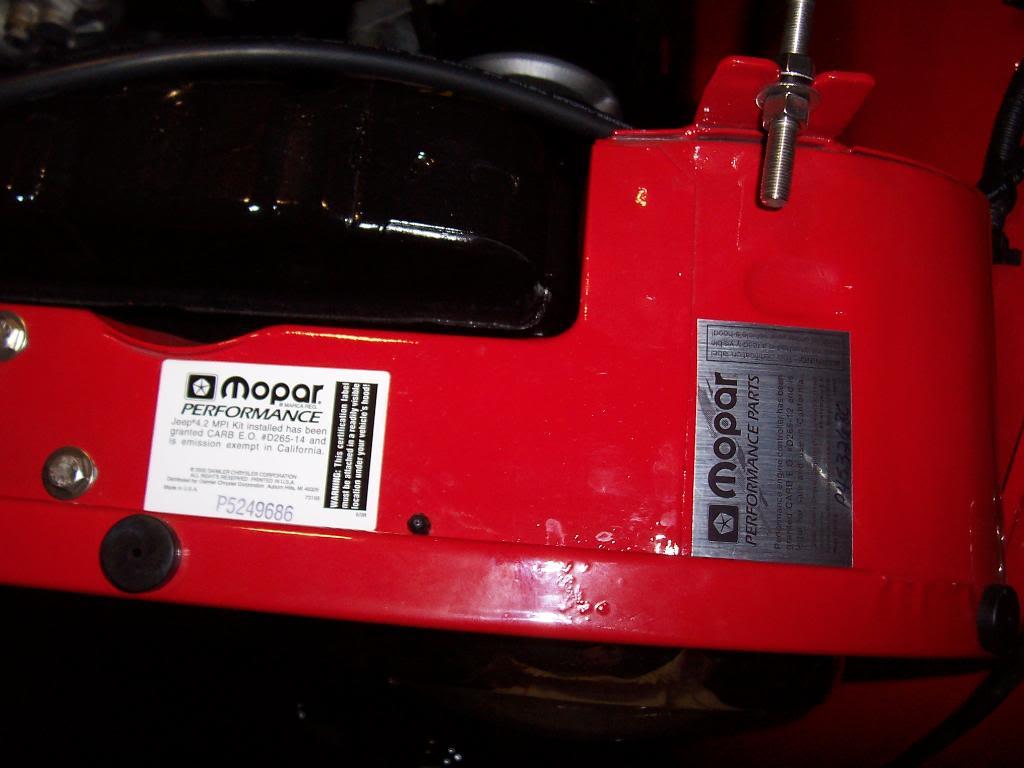
Installed the Mopar MPI under hood decals.

00325-1.jpg


00426-1.jpg


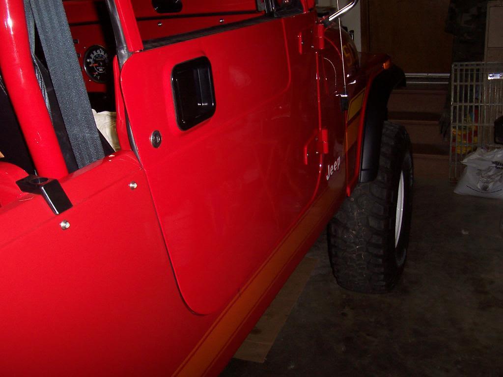
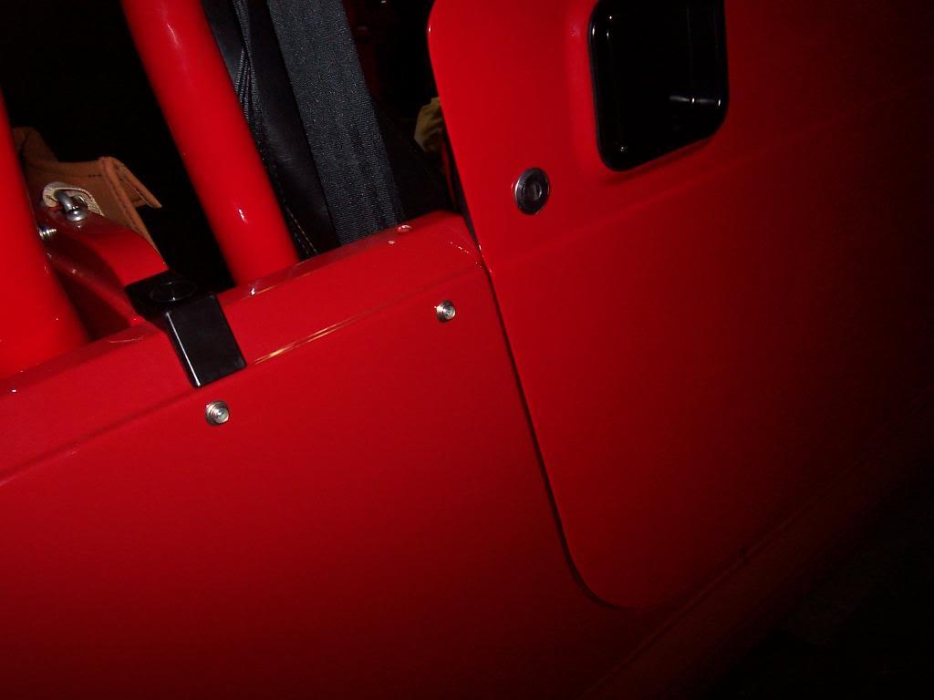
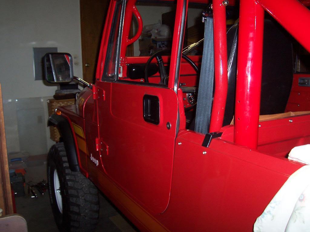
I installed new door strike posts and covers. My original strike posts were wore out and would not allow the doors to latch tightly. I also replaced my original covers with new ones, too. I bought all these parts from the Jeep dealership. They work perfectly, and now my doors shut like new.

00618-1.jpg


Picture of the passenger side door shut.

00128-1.jpg


00717-1.jpg


Pictures of the driver side door shut. This side works good, but my lower hinge post (the small bracket that bolts to the body to support the lower hinge pin) is slightly wore. I will need to replace it. It will be fun to try to color match it. I also have a small stainless spacer between the body hinge posts and the door hinge pins. I had to space the driver side door up approximately 1/8" to get it to shut right. I had this issue before I took the Jeep apart, too. I have no more upward adjustment on the door, so I had to shim it up.

00229-1.jpg


00816-1.jpg


And my first broke part.

00524-1.jpg


This is the cup that holds the transmission shifter stick firmly in place. It should not be bent. I had this same problem when I first bought this Jeep. When it bends like this, the transmission will still shift, but the stick movement is not tight, it is very sloppy, and the transmission can get hung between gears or stuck in gear. I think that my slightly wore out shift fork is causing this issue. I bent this retainer cup back straight, reinstalled it, and the shifter is tight again. I let somebody else drive the Jeep, and they were probably shifting it fast when this happened. Since I know about the slightly wore shift fork, I know how to shift it correctly so that this wont happen. Regardless, in order to fix this issue correctly, I need to buy a new shift fork.

That's it for now.
 
Raymond,

I'm referencing this thread as often (probably more) than my own pics and FSM as I reassemble my truck... thanks again for all your work to document this.

David
 
Back
Top