

You are using an out of date browser. It may not display this or other websites correctly.
You should upgrade or use an alternative browser.
You should upgrade or use an alternative browser.
Spankrjs' 1984 Long Term Project
- Thread starter spankrjs
- Start date

- City
- Biloxi
- State
- MS
Isn't that the connector for the factory jeep computer harness...
IIRC, it "might" be part of the computer harness, but it also integrates with the "normal" under hood engine wiring, need to research some more
 The computer plug is much bigger
- City
- Biloxi
- State
- MS
I was sick all weekend, plus rain, so not too much progress, but a little bit.
I found the VSS short drive shaft thingy on the floor of the Scrambler, happy about that.
I also purchased the following two items new:
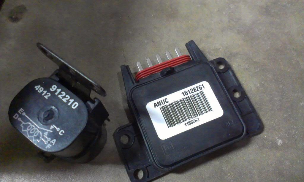
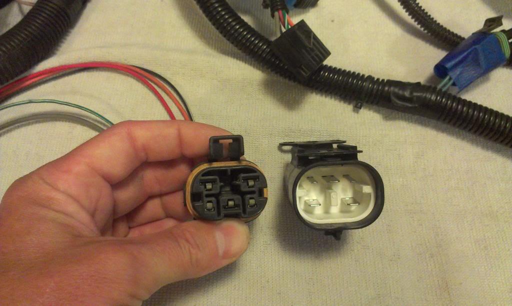
On the left, a factory style fuel pump relay. On the right, the Electronic Spark Control Module, ESCM.
I was sick Saturday, so I didn't make the Jeep Club ride, but I did go junkyard shopping for a few things:
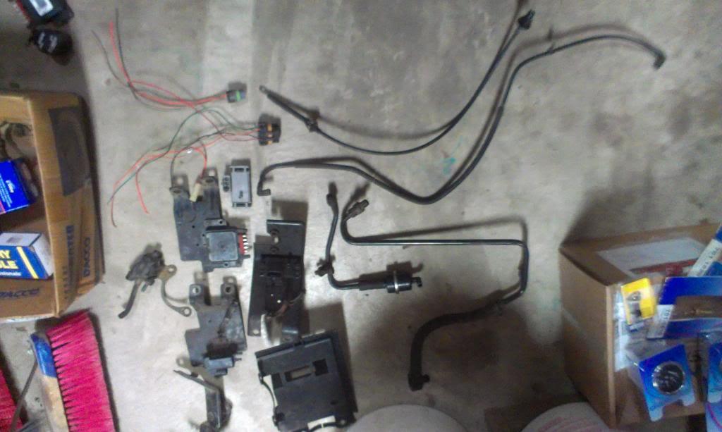
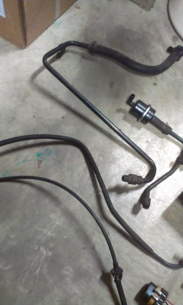
Below, the factory hard metal line that runs from the TBI unit to the power brake booster. The longer one is off a Chevy truck, the shorter unit is off a van, and the van one came with some kind of "one way valve". Should be easy enough to hook one of these lines up to the CJ brake booster. Also in the picture, a vapor can to TBI purge line and a truck throttle cable.
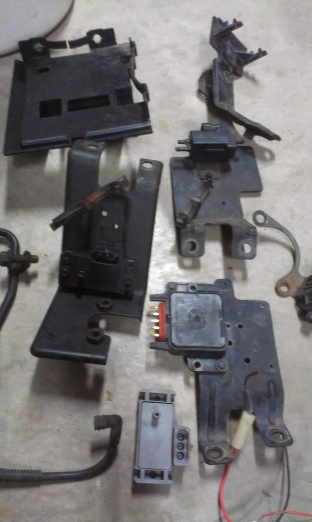
I also grabbed a PCM plastic bracket, upper left, to help mount the computer. This is found behind the dash of Chevy trucks. All of the other brackets are various ESCM/MAP/EGR sensor mounting plates, from trucks and vans. These mount on the passenger side of the intake manifold, one toward the rear, one in the middle. They provide a nice place to mount these sensors. I grabbed these items off of several different year trucks/vans, and will use the two that work best for me, and the length of my harness. I will be able to adapt some of these to my engine so that I will have a "clean" install, vs a bunch of suff screwed to the firewall or dangling about.
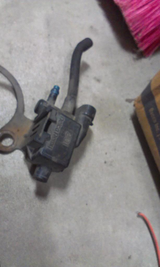
I also grabbed this doo-hickey off a truck, mounted to the thermostat housing. I believe it is a "vapor canister purge" solenoid thing. I do not think my harness has the wires for this, though. I will have to come up with a way to purge the vapor canister.
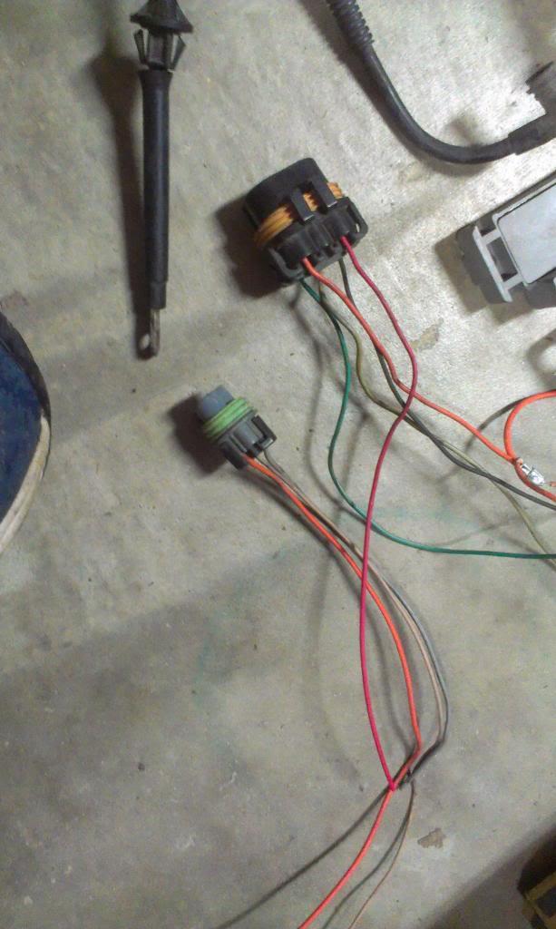
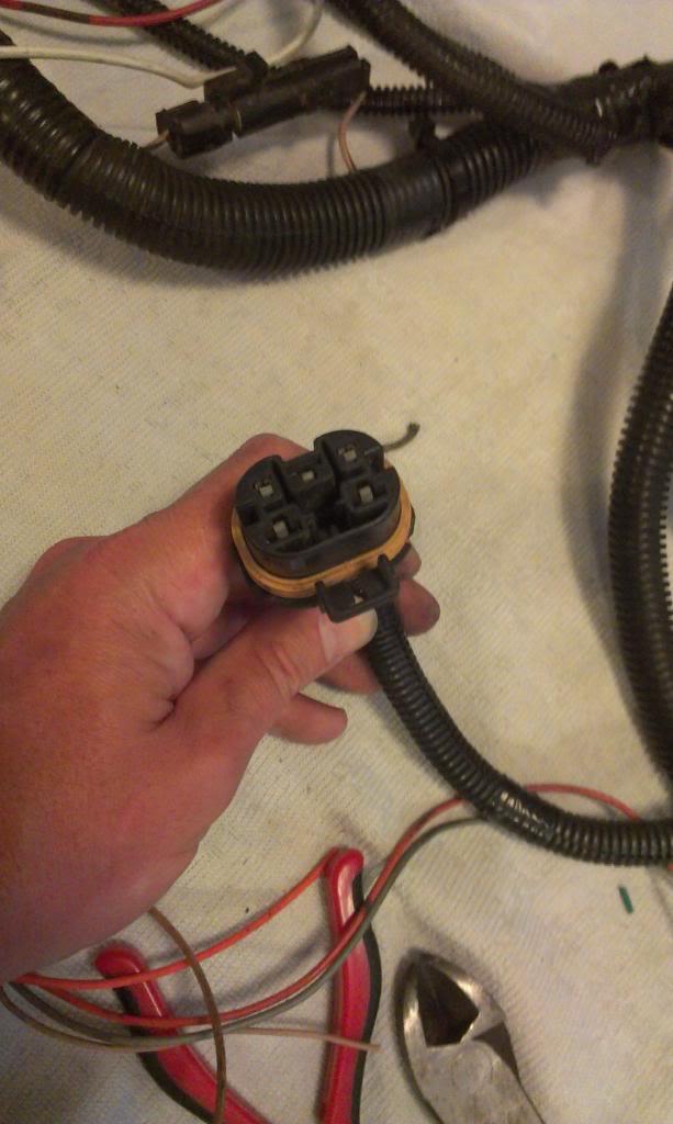
I also grabbed a spare "fuel pump relay" section of harness. Every TBI equipped Chevy truck/van I saw at the junk yard had this style relay. I was surprised the aftermarket harness did not come with this style connector. I also grabbed another oil pressure switch harness, to lengthen mine. I only found one vehicle in the junkyard that had the same style oil pressure switch as mine, located on the driver side of the block, down by the oil filter housing. I must have looked at around 40 87-95 350 TBI set ups, but only one other vehicle had this style oil pressure switch. Weird.
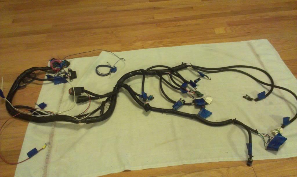
I pulled the TBI harness back off the Jeep, so it would be easier to figure out what my "mystery connectors" are for.
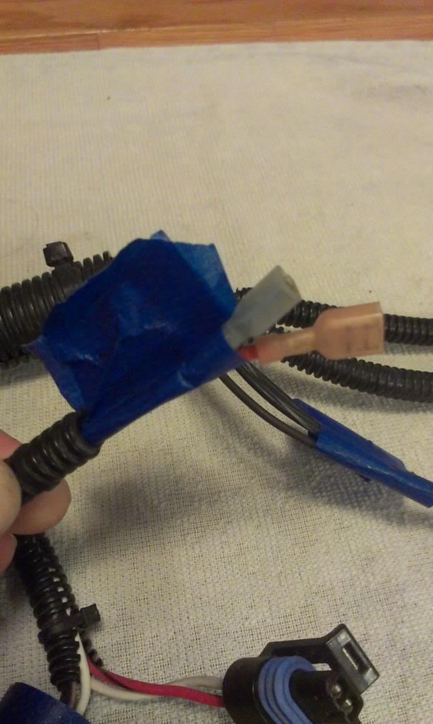
First mystery solved. These two wires are part of the fuel pump relay circuit. They both connect to the oil pressure switch, located on the driver side of the engine block. Should be easy enough. Not even sure if I will use this feature, maybe "by-pass" it.
And my second mystery solved. This connector is for a "fuel pump relay", which my harness did not come with.
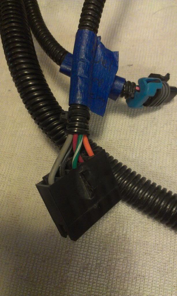
I cut the above connector off of the aftermarket TBI harness and spliced in a factory GM fuel pump relay connector. Maybe not necessary, but I like it much better. All of the Turbo City wire colors matched the GM colors perfectly, pretty easy modifications.
I found the VSS short drive shaft thingy on the floor of the Scrambler, happy about that.
I also purchased the following two items new:
On the left, a factory style fuel pump relay. On the right, the Electronic Spark Control Module, ESCM.
I was sick Saturday, so I didn't make the Jeep Club ride, but I did go junkyard shopping for a few things:
Below, the factory hard metal line that runs from the TBI unit to the power brake booster. The longer one is off a Chevy truck, the shorter unit is off a van, and the van one came with some kind of "one way valve". Should be easy enough to hook one of these lines up to the CJ brake booster. Also in the picture, a vapor can to TBI purge line and a truck throttle cable.
I also grabbed a PCM plastic bracket, upper left, to help mount the computer. This is found behind the dash of Chevy trucks. All of the other brackets are various ESCM/MAP/EGR sensor mounting plates, from trucks and vans. These mount on the passenger side of the intake manifold, one toward the rear, one in the middle. They provide a nice place to mount these sensors. I grabbed these items off of several different year trucks/vans, and will use the two that work best for me, and the length of my harness. I will be able to adapt some of these to my engine so that I will have a "clean" install, vs a bunch of suff screwed to the firewall or dangling about.
I also grabbed this doo-hickey off a truck, mounted to the thermostat housing. I believe it is a "vapor canister purge" solenoid thing. I do not think my harness has the wires for this, though. I will have to come up with a way to purge the vapor canister.
I also grabbed a spare "fuel pump relay" section of harness. Every TBI equipped Chevy truck/van I saw at the junk yard had this style relay. I was surprised the aftermarket harness did not come with this style connector. I also grabbed another oil pressure switch harness, to lengthen mine. I only found one vehicle in the junkyard that had the same style oil pressure switch as mine, located on the driver side of the block, down by the oil filter housing. I must have looked at around 40 87-95 350 TBI set ups, but only one other vehicle had this style oil pressure switch. Weird.
I pulled the TBI harness back off the Jeep, so it would be easier to figure out what my "mystery connectors" are for.
First mystery solved. These two wires are part of the fuel pump relay circuit. They both connect to the oil pressure switch, located on the driver side of the engine block. Should be easy enough. Not even sure if I will use this feature, maybe "by-pass" it.
And my second mystery solved. This connector is for a "fuel pump relay", which my harness did not come with.
I cut the above connector off of the aftermarket TBI harness and spliced in a factory GM fuel pump relay connector. Maybe not necessary, but I like it much better. All of the Turbo City wire colors matched the GM colors perfectly, pretty easy modifications.
- City
- Biloxi
- State
- MS
And installed.
Pictured below are two oil pressure switch harnesses. This is for an oil pressure switch, not the pressure gauge. The lower one came off of my engine, the upper one came from the junkyard. Both are 3 wire switches. Two of the wires are for the fuel pump relay, the center wire is for a gauge warning light, and will not be used. Note the difference.
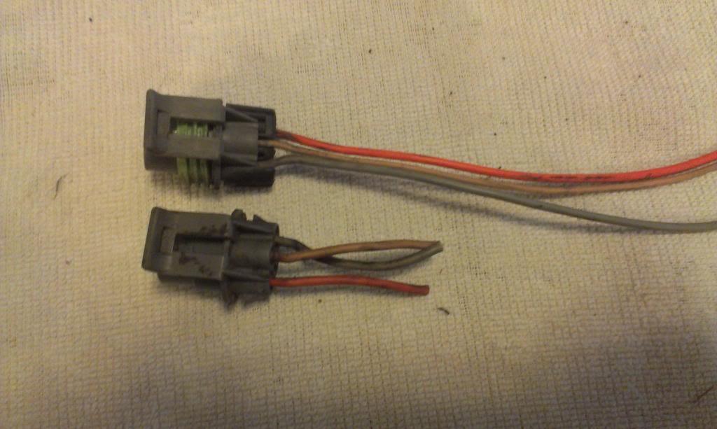
The orange and gray wires, which I need, are reversed!! The connector is "keyed", so it will only go on one way. I was thinking I was going to have to take the connector apart to switch the wires, then I remember this:
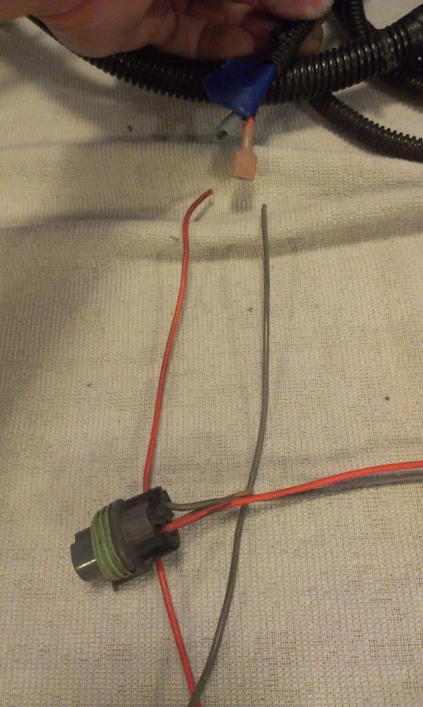
The harness end has female spade connectors, so I can just "reverse the wires" at this connection, easy enough.
I previously purchased some new gauges:
engine oil pressure
engine coolant temp
transmission fluid temp (kind of retarded this gauge goes to 400 degrees!!!!!!!!!!!!!!!!!!!!)

I need to install the transmission fluid sending unit in the pan, before I fill it with fluid and try to start the engine. I already have a drain plug at the bottom of the transmission pan, but this would not be a good place for this sender unit. My solution:

I am going to drill another hole in the pan, on the back side (low end) toward the bottom. I will then screw in the universal drain plug kit, and thread the sender unit into this. I still need to install this, but will be a fairly simple project.
I reinstalled the TBI harness, and started correcting some previously found issues.
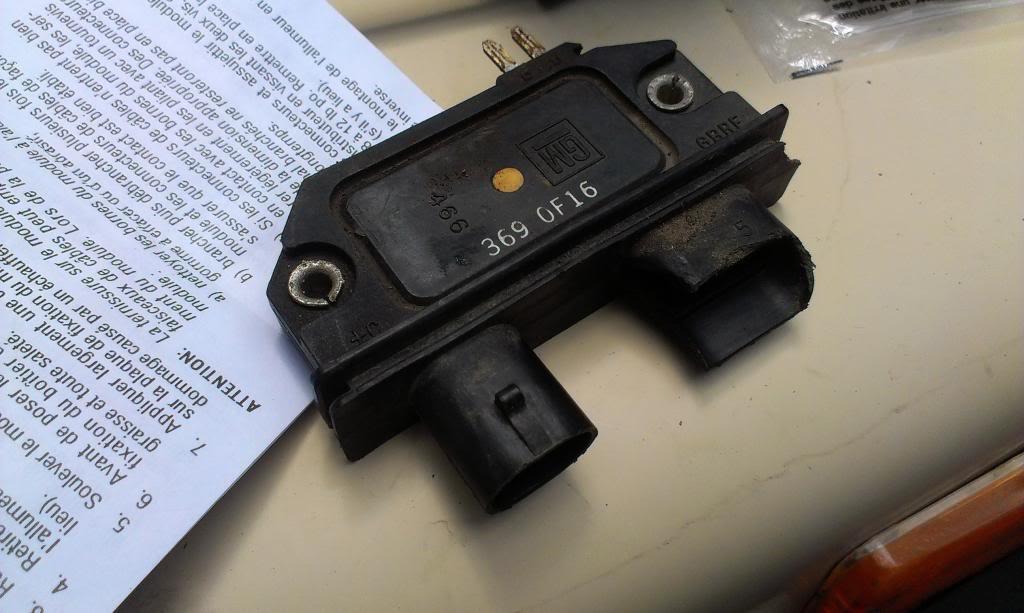
This module was broken, but a new one came with the Jeep. Easy/cheap fix.
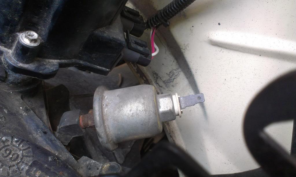
While I was back there, I also switched out the oil pressure gauge sending units. Pictured below is the factory unit. It has a fitting that goes to the block, not the intake manifold (looks like it in the pictures). I did not see any other GM TBI 350's at the junkyard like this, is this rare???
Pictured below are two oil pressure switch harnesses. This is for an oil pressure switch, not the pressure gauge. The lower one came off of my engine, the upper one came from the junkyard. Both are 3 wire switches. Two of the wires are for the fuel pump relay, the center wire is for a gauge warning light, and will not be used. Note the difference.
The orange and gray wires, which I need, are reversed!! The connector is "keyed", so it will only go on one way. I was thinking I was going to have to take the connector apart to switch the wires, then I remember this:
The harness end has female spade connectors, so I can just "reverse the wires" at this connection, easy enough.
I previously purchased some new gauges:
engine oil pressure
engine coolant temp
transmission fluid temp (kind of retarded this gauge goes to 400 degrees!!!!!!!!!!!!!!!!!!!!)
I need to install the transmission fluid sending unit in the pan, before I fill it with fluid and try to start the engine. I already have a drain plug at the bottom of the transmission pan, but this would not be a good place for this sender unit. My solution:
I am going to drill another hole in the pan, on the back side (low end) toward the bottom. I will then screw in the universal drain plug kit, and thread the sender unit into this. I still need to install this, but will be a fairly simple project.
I reinstalled the TBI harness, and started correcting some previously found issues.
This module was broken, but a new one came with the Jeep. Easy/cheap fix.
While I was back there, I also switched out the oil pressure gauge sending units. Pictured below is the factory unit. It has a fitting that goes to the block, not the intake manifold (looks like it in the pictures). I did not see any other GM TBI 350's at the junkyard like this, is this rare???
- City
- Biloxi
- State
- MS
When I was looking in the repair manual, all the pictures showed the valve covers being oriented differently then how my engine came. Pictured below is how they sit on my engine.
Passenger side:
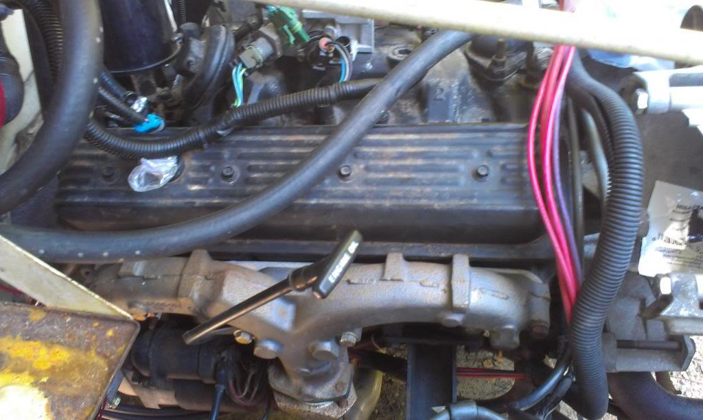
Driver side:
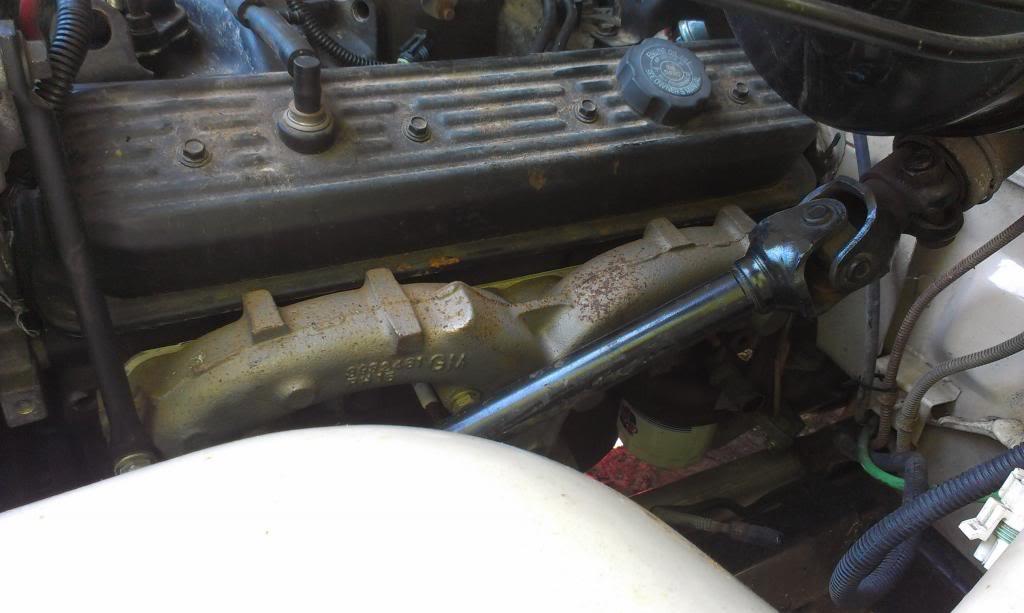
This is not a problem, but the oil fill is in a pain in the butt location. I can't just rotate each side 180 degrees because the retaining bolt holes wont line up. If I can, I am going to swap the covers side to side, so that the oil fill hole ends up on the passenger side cover, at the front of the engine.
My engine came with these "ram horn" style exhaust manifolds. They are supposed to be the good ones?? One issue with them, they lightly contact the valve covers. So, to pull the covers, I had to drop the exhaust, then loosen the manifolds. I will probably grind each manifold so that they will not contact the valve covers.
Curiosity got the best of me, so I pulled the covers.
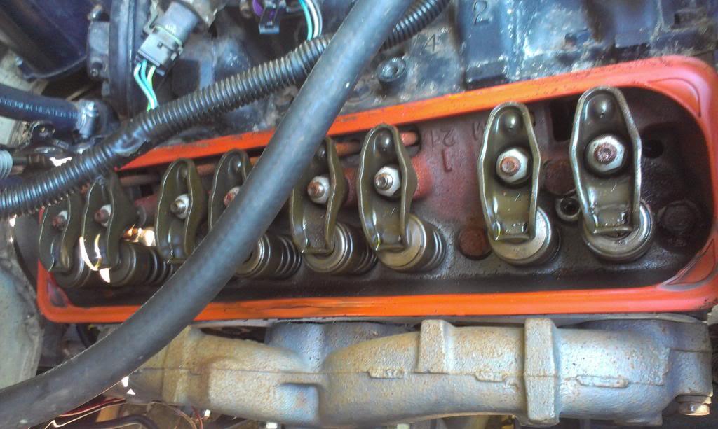
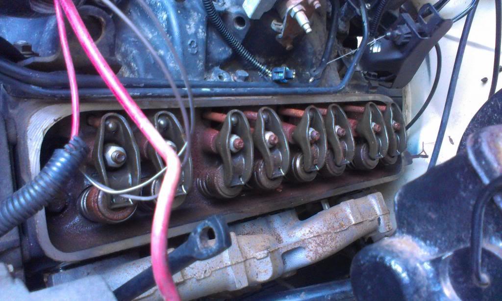
One of the gaskets tore, so I replaced them both. No sign of sludge, no sign of anything, except light surface rust, which concerns me. It is not enough rust to hurt anything, and I guess it will "disappear" once I start the engine up. Is this something I should be worried about?? I do not think this engine has turned over in a long, long, long, long time. The pan is full of "new looking" oil, and the crank will turn over with a ratchet, so it is not locked up. My plan is to start the engine with the oil it has, let it run about 20 minutes, then change the oil. Maybe do a few more quick oil/filter changes to catch any loose surface rust?? Maybe a quart of trans fluid with the oil to help "clean" it up??? I am going to disconnect the fuel/ignition the first few times I eventually initially turn it over, so that it has been "lubed".
The next few days will probably consist of more under hood wiring.
That's it for now.
Passenger side:
Driver side:
This is not a problem, but the oil fill is in a pain in the butt location. I can't just rotate each side 180 degrees because the retaining bolt holes wont line up. If I can, I am going to swap the covers side to side, so that the oil fill hole ends up on the passenger side cover, at the front of the engine.
My engine came with these "ram horn" style exhaust manifolds. They are supposed to be the good ones?? One issue with them, they lightly contact the valve covers. So, to pull the covers, I had to drop the exhaust, then loosen the manifolds. I will probably grind each manifold so that they will not contact the valve covers.
Curiosity got the best of me, so I pulled the covers.
One of the gaskets tore, so I replaced them both. No sign of sludge, no sign of anything, except light surface rust, which concerns me. It is not enough rust to hurt anything, and I guess it will "disappear" once I start the engine up. Is this something I should be worried about?? I do not think this engine has turned over in a long, long, long, long time. The pan is full of "new looking" oil, and the crank will turn over with a ratchet, so it is not locked up. My plan is to start the engine with the oil it has, let it run about 20 minutes, then change the oil. Maybe do a few more quick oil/filter changes to catch any loose surface rust?? Maybe a quart of trans fluid with the oil to help "clean" it up??? I am going to disconnect the fuel/ignition the first few times I eventually initially turn it over, so that it has been "lubed".
The next few days will probably consist of more under hood wiring.
That's it for now.

- City
- Gordonsville
- State
- VA
I'd pull the distributer and prime the engine with a drill!  I would take the chance of screwing up that engine before you ever get to run it.
I would take the chance of screwing up that engine before you ever get to run it.I am going to disconnect the fuel/ignition the first few times I eventually initially turn it over, so that it has been "lubed".
QUOTE]

- City
- Cobourg, Ontario, Cana
- State
- da
I'd pull the distributer and prime the engine with a drill!
I am going to disconnect the fuel/ignition the first few times I eventually initially turn it over, so that it has been "lubed".
QUOTE]
yup easy. if you dont want to buy the proper "luber" just get a long flat head screw driver and cut the handle off, insert in drill and youre good. works like a charm.

- City
- Dexter
- State
- MI
yup easy. if you dont want to buy the proper "luber" just get a long flat head screw driver and cut the handle off, insert in drill and youre good. works like a charm.
I cut up an old stock dizzy to use to prelube my 360, that way it had top and bottom bushings to keep things aligned. Shaft chucked right into my drill. Had the dizzy sitting there so it was a free tool that can't slip or otherwise screw anything up. There's a pretty good load on the tool once it starts pumping oil, so I was glad to have it.
- City
- Biloxi
- State
- MS
I'd pull the distributer and prime the engine with a drill!
I am going to disconnect the fuel/ignition the first few times I eventually initially turn it over, so that it has been "lubed".
QUOTE]
yup easy. if you dont want to buy the proper "luber" just get a long flat head screw driver and cut the handle off, insert in drill and youre good. works like a charm.
I cut up an old stock dizzy to use to prelube my 360, that way it had top and bottom bushings to keep things aligned. Shaft chucked right into my drill. Had the dizzy sitting there so it was a free tool that can't slip or otherwise screw anything up. There's a pretty good load on the tool once it starts pumping oil, so I was glad to have it.
Just making sure y'all were still awake
Yes, I think I will "pre-lube it", it looked pretty dry

- City
- Biloxi
- State
- MS
Some more under hood work. Not too exciting, but it needed to be done. Slowly crawling forward, still lots, and lots, and lots, and lots to do before this thing will run.
The "ram horn" style exhaust manifolds were smashed up against the valve cover flange. So, I pulled them off and ground down the four raised spots to prevent contact.
Showing the contact areas.
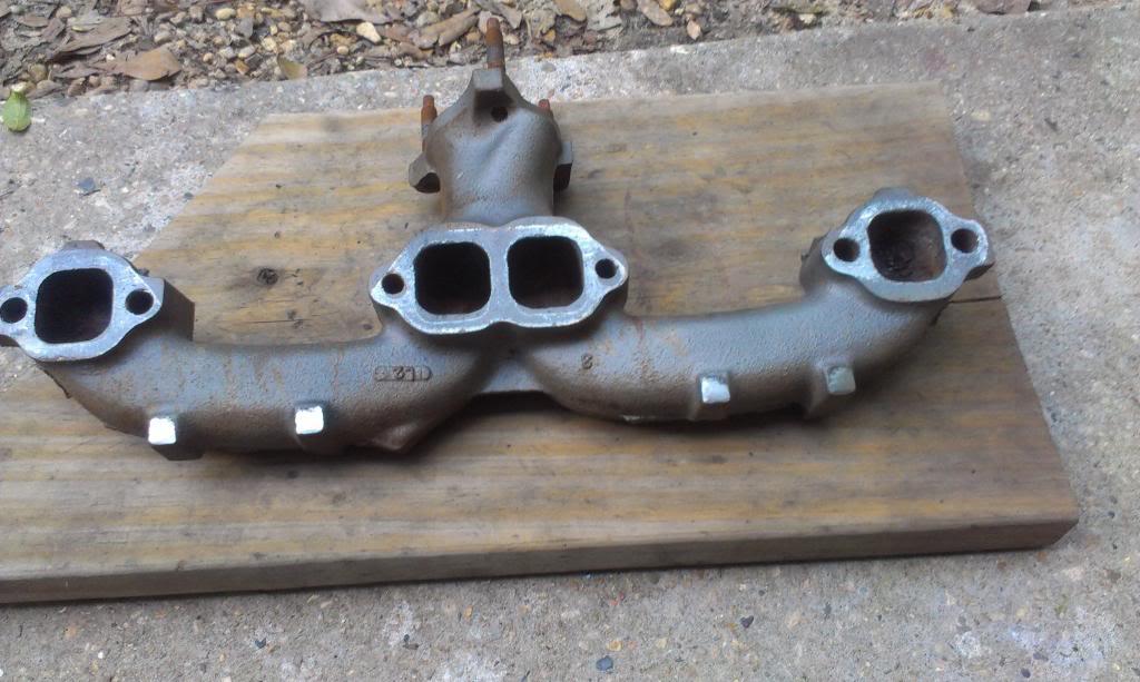
Test fit, not enough ground off yet.
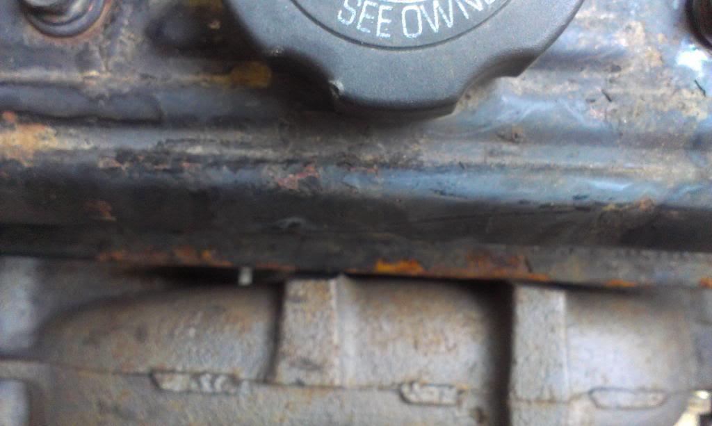
And done. The back yard lathe, aka angle grinder, made quick work of this.
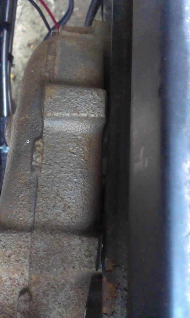
The passenger side was easy. On the driver side, bigger pain in the butt. This motor is offset to the driver side to enable maximum front driveshaft clearance. As a result, the manifold can not be removed easily. I had to remove the lower steering shaft coupler from the steering box, then remove the six bolts that retain the steering column to the firewall/dash bracket. Once that was done, I could remove the exhaust manifold. A bunch of work to get the manifold out, for a few minutes on the grinder.
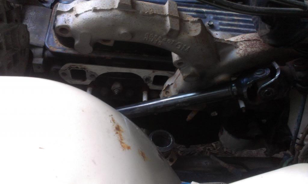
When I removed the driver side manifold, I found the temperature gauge sending unit. I will need to install my VDO temp sender gauge here. Easy enough. I read that this sender unit is usually in the passenger side head, but mine is on the driver side head. No big deal either way.
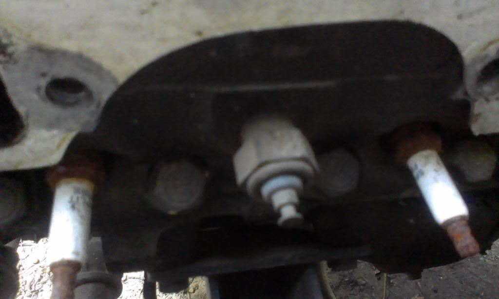
After the exhaust manifolds were torqued back down, I swapped the valve covers from side to side, front to back. Worked perfect. My oil fill cap is much more accessible now. A small/simple/bolt on modification, but it is much more convenient now.
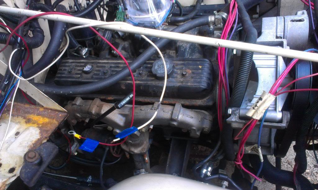
In order to swap the valve covers, I had to remove the alternator. I needed to do this anyway, to see what type of alternator I have, so I can hook it up correctly.
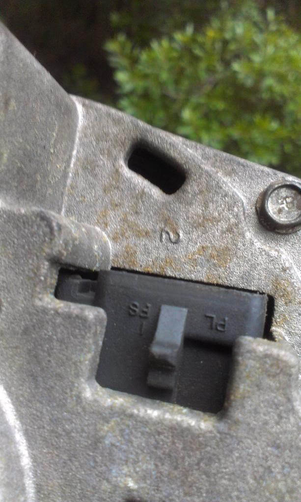
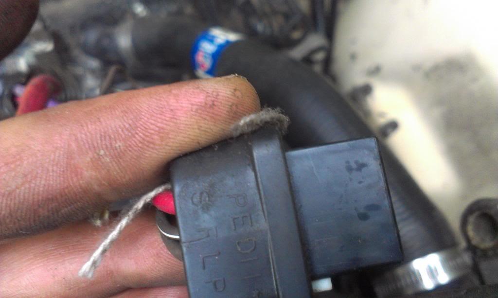
The only screwy thing with my alternator - I need to install a 50ohm resistor in the 12 volt ignition hot/excitor wire to function correctly. I will also need to hook up the "remote sensor" wire to a random, 12 volt hot on run wire in the harness, so that the alternator will know when/how much to charge. The big wire goes the alternator, and a smaller red wire jumps from the alternators "Batt" post to this plug. Should be easy enough.
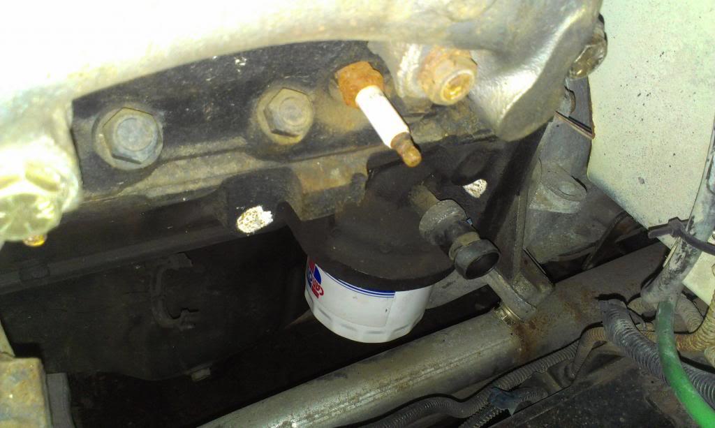
I don't know why I kept thinking/saying my oil pressure switch was in the block - it is not. It is on an extension coming off of the oil filter housing. I "might" need to swap this sensor for the "two-wire" type, not 100% sure yet.
I am going to work on a few more "mechanical" type problems under the hood before I jump back into the wiring side of things. I needed a break from wiring LOL.
That's it for now
The "ram horn" style exhaust manifolds were smashed up against the valve cover flange. So, I pulled them off and ground down the four raised spots to prevent contact.
Showing the contact areas.
Test fit, not enough ground off yet.
And done. The back yard lathe, aka angle grinder, made quick work of this.
The passenger side was easy. On the driver side, bigger pain in the butt. This motor is offset to the driver side to enable maximum front driveshaft clearance. As a result, the manifold can not be removed easily. I had to remove the lower steering shaft coupler from the steering box, then remove the six bolts that retain the steering column to the firewall/dash bracket. Once that was done, I could remove the exhaust manifold. A bunch of work to get the manifold out, for a few minutes on the grinder.
When I removed the driver side manifold, I found the temperature gauge sending unit. I will need to install my VDO temp sender gauge here. Easy enough. I read that this sender unit is usually in the passenger side head, but mine is on the driver side head. No big deal either way.
After the exhaust manifolds were torqued back down, I swapped the valve covers from side to side, front to back. Worked perfect. My oil fill cap is much more accessible now. A small/simple/bolt on modification, but it is much more convenient now.
In order to swap the valve covers, I had to remove the alternator. I needed to do this anyway, to see what type of alternator I have, so I can hook it up correctly.
The only screwy thing with my alternator - I need to install a 50ohm resistor in the 12 volt ignition hot/excitor wire to function correctly. I will also need to hook up the "remote sensor" wire to a random, 12 volt hot on run wire in the harness, so that the alternator will know when/how much to charge. The big wire goes the alternator, and a smaller red wire jumps from the alternators "Batt" post to this plug. Should be easy enough.
I don't know why I kept thinking/saying my oil pressure switch was in the block - it is not. It is on an extension coming off of the oil filter housing. I "might" need to swap this sensor for the "two-wire" type, not 100% sure yet.
I am going to work on a few more "mechanical" type problems under the hood before I jump back into the wiring side of things. I needed a break from wiring LOL.
That's it for now

- City
- Redmond
- State
- OR
Chevy can have oil pressure ports in both places- at the rear of the valley by the distributor, or above the oil filter, or both.
I prefer using the cut off distributor as a lube tool- it directs oil to all passages so the top end gets fully lubed.
I've got a spare if you need it.
I prefer using the cut off distributor as a lube tool- it directs oil to all passages so the top end gets fully lubed.
I've got a spare if you need it.
- City
- Biloxi
- State
- MS
Chevy can have oil pressure ports in both places- at the rear of the valley by the distributor, or above the oil filter, or both.
I prefer using the cut off distributor as a lube tool- it directs oil to all passages so the top end gets fully lubed.
I've got a spare if you need it.
Appreciate it Randy, but I got a buddy down the street who is a die hard Chevy fanatic, he should have something

Thanks for clearing up the oil pressure port issue
- City
- Biloxi
- State
- MS
Finally feel like I am making forward progress again. Most of these recent posts all show a bunch of "minor detail work", not big glamorous accomplishments. But, it is all of these little things that take the most time, and are necessary for this thing to eventually run. I hope some of this might be helpful to others. I am trying to do this stuff as clean/neat/easy/makes the most sense as possible.
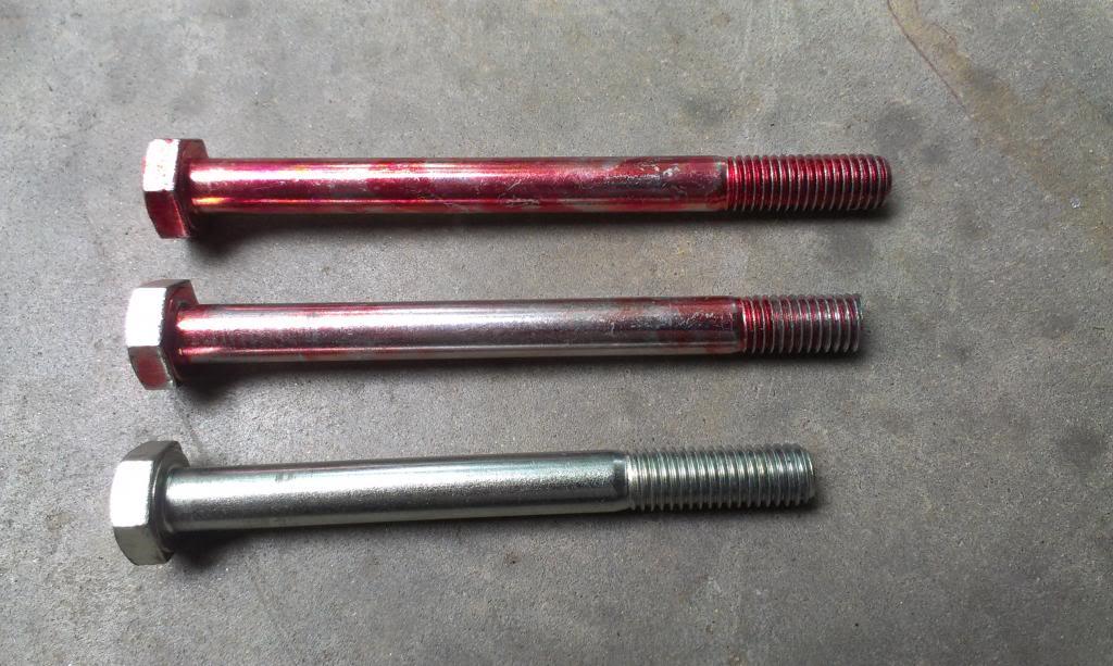
Quick picture of my new AC Delete bolts. I believe GM use 115mm long bolts, and none of the close by stores sell bolts that size. 120mm is too long (TOP), 100mm is too short (BOTTOM), a Dremel tool made the 120's just right(MIDDLE). Since AC compressors go fast at the junkyard, I could not find any bolts there. Quick and easy job.
And installed. I used two flat washers on the back, so I could have used slightly shorter bolts. But, I might use this "extra space at the bolt head end" to secure some cable clamps in the near future, so no big deal.
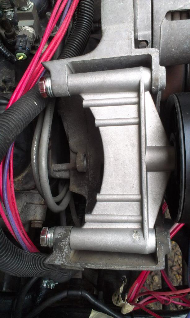
Note how too long of a bolt will hit the belt/pulley.

I then started working on mounting the last of the TBI sensors. I used a factory Chevy bracket to mount the ESCM. From the factory, the ESCM harness is longer then what came with my aftermarket harness. Stock, the ESCM plug faces forward. My harness was too short to reach this way. So, I simply spun the ESCM around backwards, slid it to the back of the bracket, drilled one new hole, and a pretty clean install.
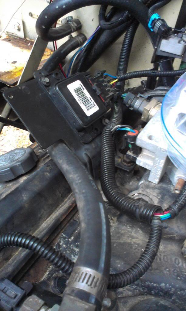
For my MAP sensor, I again used a factory Chevy bracket. It bolts on the intake using one of the factory installed studs. The aftermarket TBI harness reaches this location perfectly. I noticed some stock MAP sensors are bolted directly to this bracket. I used the stock bracket, couple with a stock plastic "MAP SENSOR HOLDER" thingy. It was a hair loose, so I used two cable ties to positively secure it. Probably over kill, but I figured the MAP sensor shouldn't be vibrating around. When using the plastic bracket, the harness plug/vacuum port face downwards.

I had one more sensor to mount, the EGR solenoid. But, I have 3 different sensors left over, but two came from the junk yard. After some research, I believe the below sensors are as follows, from left to right:
1) The vapor canister purge solenoid (my harness does not support this feature)
2) An "early" EGR solenoid
3) A "later" EGR solenoid

I decided to use the "later" EGR solenoid, since I found info on how it hooks up. One port goes to the TB, one goes to the EGR, and the third, non barbed port, with the bit of foam, is a breather.
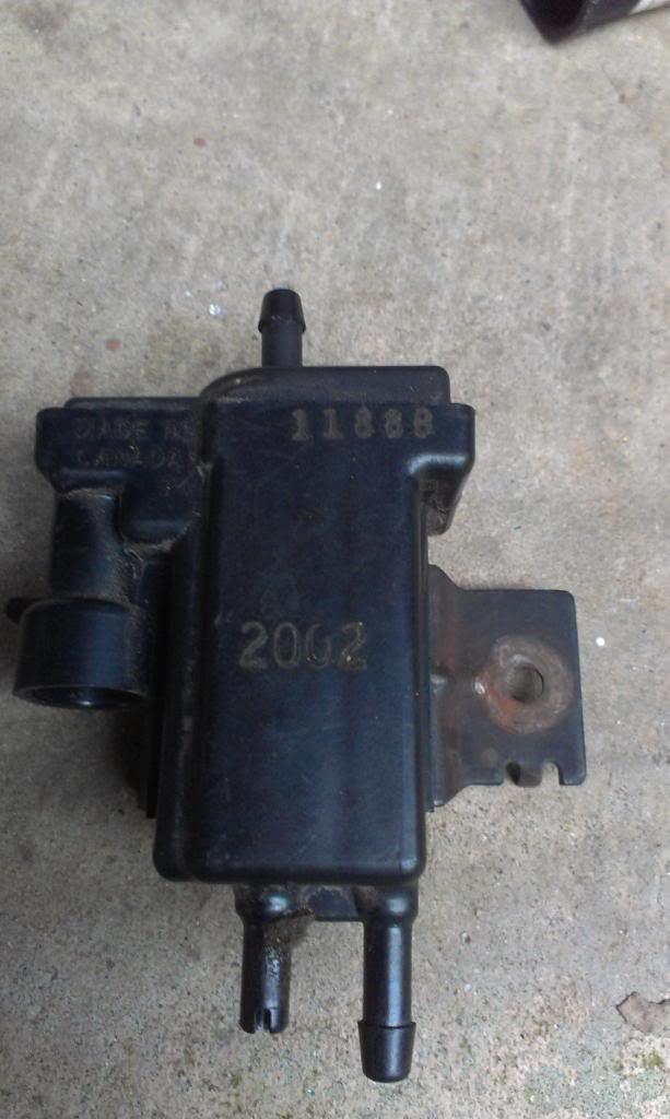
Due to my aftermarket harness length, and ease of mounting, I bolted this sensor on to the previously installed MAP sensor bracket. Super easy, no modifications necessary, it bolted right on, and the harness reaches perfectly. Pretty clean install.
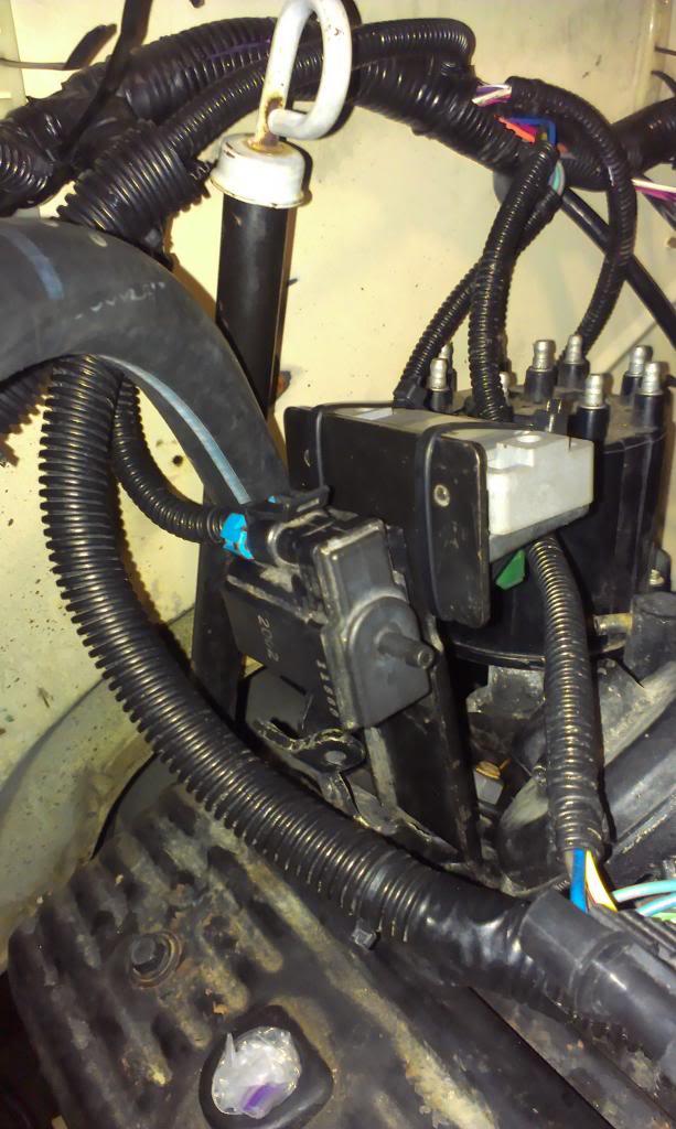
While I was at the junkyard, I noticed that some GM vehicles had all three sensors (EGR/MAP/ESCM) all mounted to the larger ESCM bracket I previously showed. I would have preferred to mount all 3 sensors to one bracket, but my harness wouldn't reach, and I don't have time to lengthen it right now. But, I think this works pretty well, too, and it will result in shorter vacuum lines to one EGR sensor port and the MAP sensor. But, it is getting crowded on the back of the intake.
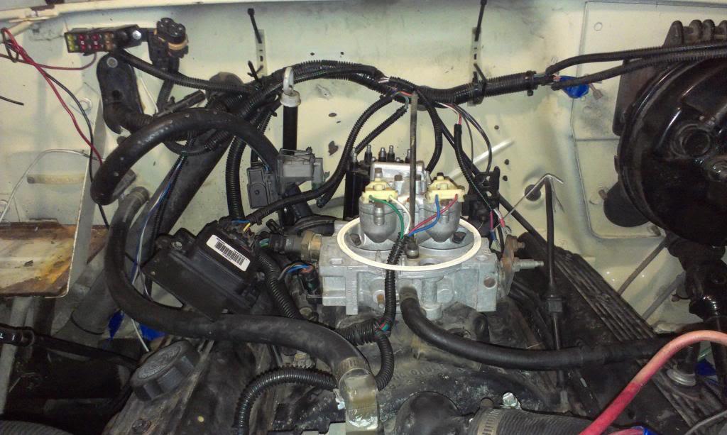
And a quick "current" shot. The TBI stuff has a bunch of wires, kind of hard to get it real "pretty". My install still has a bunch more "prettying up" to be done, so it will eventually look a bit better, maybe?? Only so much you can do with this many wires/sensors all being mounted to the intake/TBI unit. Not a lot of real estate for a bunch of stuff!!!
Quick picture of my new AC Delete bolts. I believe GM use 115mm long bolts, and none of the close by stores sell bolts that size. 120mm is too long (TOP), 100mm is too short (BOTTOM), a Dremel tool made the 120's just right(MIDDLE). Since AC compressors go fast at the junkyard, I could not find any bolts there. Quick and easy job.
And installed. I used two flat washers on the back, so I could have used slightly shorter bolts. But, I might use this "extra space at the bolt head end" to secure some cable clamps in the near future, so no big deal.
Note how too long of a bolt will hit the belt/pulley.
I then started working on mounting the last of the TBI sensors. I used a factory Chevy bracket to mount the ESCM. From the factory, the ESCM harness is longer then what came with my aftermarket harness. Stock, the ESCM plug faces forward. My harness was too short to reach this way. So, I simply spun the ESCM around backwards, slid it to the back of the bracket, drilled one new hole, and a pretty clean install.
For my MAP sensor, I again used a factory Chevy bracket. It bolts on the intake using one of the factory installed studs. The aftermarket TBI harness reaches this location perfectly. I noticed some stock MAP sensors are bolted directly to this bracket. I used the stock bracket, couple with a stock plastic "MAP SENSOR HOLDER" thingy. It was a hair loose, so I used two cable ties to positively secure it. Probably over kill, but I figured the MAP sensor shouldn't be vibrating around. When using the plastic bracket, the harness plug/vacuum port face downwards.
I had one more sensor to mount, the EGR solenoid. But, I have 3 different sensors left over, but two came from the junk yard. After some research, I believe the below sensors are as follows, from left to right:
1) The vapor canister purge solenoid (my harness does not support this feature)
2) An "early" EGR solenoid
3) A "later" EGR solenoid
I decided to use the "later" EGR solenoid, since I found info on how it hooks up. One port goes to the TB, one goes to the EGR, and the third, non barbed port, with the bit of foam, is a breather.
Due to my aftermarket harness length, and ease of mounting, I bolted this sensor on to the previously installed MAP sensor bracket. Super easy, no modifications necessary, it bolted right on, and the harness reaches perfectly. Pretty clean install.
While I was at the junkyard, I noticed that some GM vehicles had all three sensors (EGR/MAP/ESCM) all mounted to the larger ESCM bracket I previously showed. I would have preferred to mount all 3 sensors to one bracket, but my harness wouldn't reach, and I don't have time to lengthen it right now. But, I think this works pretty well, too, and it will result in shorter vacuum lines to one EGR sensor port and the MAP sensor. But, it is getting crowded on the back of the intake.
And a quick "current" shot. The TBI stuff has a bunch of wires, kind of hard to get it real "pretty". My install still has a bunch more "prettying up" to be done, so it will eventually look a bit better, maybe?? Only so much you can do with this many wires/sensors all being mounted to the intake/TBI unit. Not a lot of real estate for a bunch of stuff!!!
Last edited:
- City
- Biloxi
- State
- MS
The last TBI/ignition components I have to install are the coil and the fuel pump relay.
This aftermarket TBI harness was made to use an aftermarket, "can" style coil. I don't know why it wasn't made to use the factory style coil. That would have been a simple, bolt on install. So, I am just going to make a "flat plate" bracket that will bolt to the firewall using two of the "brake booster to firewall bolts" to secure it. I will then bolt on a universal "can clamp" mount to this plate. Harness length wise, this is the best place to mount it. The fire wall is too busy with wires already, and I don't want to needlessly drill holes through the firewall.

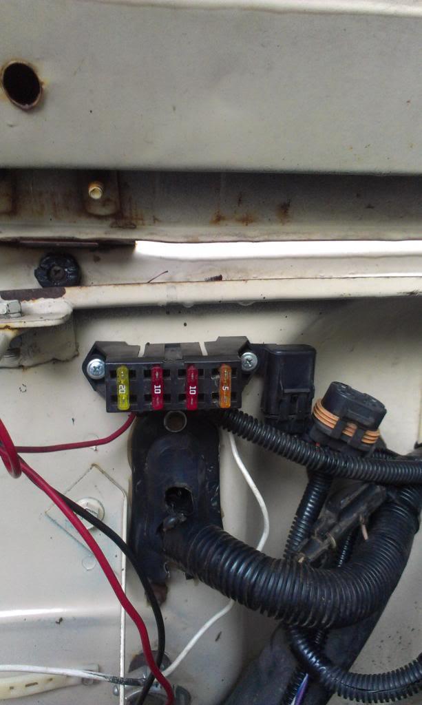
For the fuel pump relay mount, since the previous owner already drilled two holes through the firewall to mount the harness fuse panel, I will use these two holes. I am just going to bolt a metal strip to the firewall here, using the two previously drilled holes. I will then bolt the fuse panel, fuel pump fuse holder, and then the fuel pump relay to this strip, in this order. That way, everything will be together, neat, and easy to get too, with no additional firewall holes.
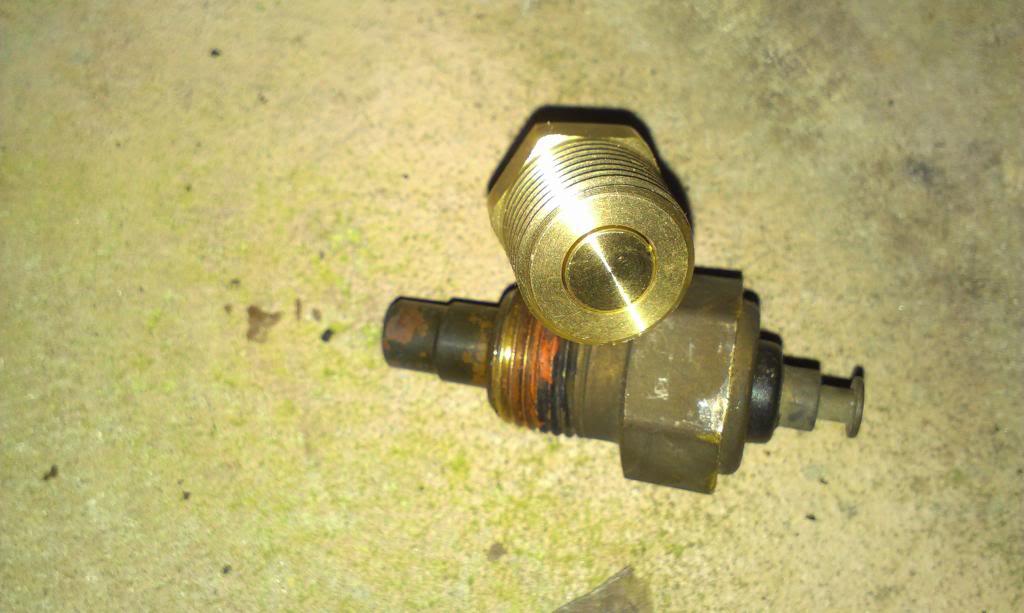
And I completed one more "easy task". I needed to install the VDO temperature gauge sender in the engine. I pulled the factory sender out of the head, and of course it is bigger. Quick trip to Lowes solved this problem.
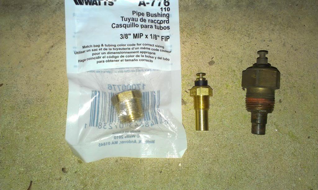
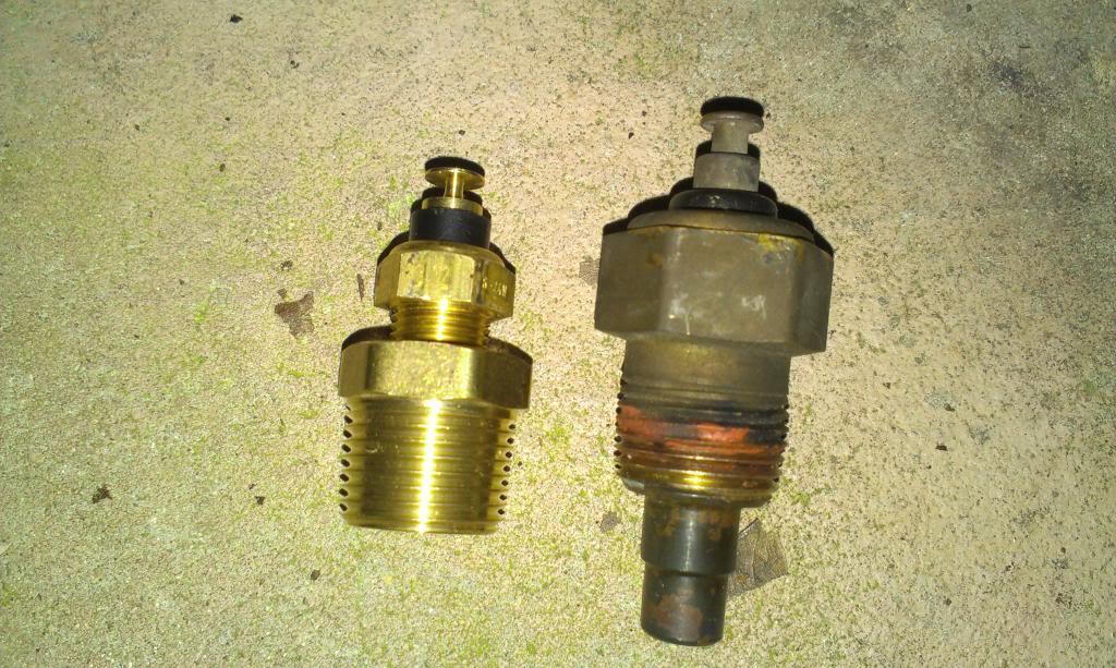
I noticed this when I was messing around with the "not yet installed" transmission temperature sending unit - the sender "probe" will not be sticking out into the coolant like the stock one does. I don't think this matters, the sender will still be in contact with the hot fluid, so probably doesn't matter??
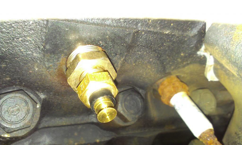
And installed, with no leaks!!!
I am going to start on the rest of the under hood wiring soon. I might drop the exhaust (to get O2 bung welded in) next, and while it is down, also drop the transmission pan to install the transmission temperature gauge sender.
I also want to drop the transmission pan to see exactly what kind of solenoids/wiring it has, so I know how to wire it up. Since I am using a stock computer, it should control the transmission through the harness supplied TCC plug. But, my harness also has a "Top Gear" wire coming out of it. Not sure if I need to hook this up?? I also have a VSS to install and wire up. And, if I am correct, I need to run the TCC power wire thought a brake pedal switch, or a "relay", so that it will unlock the torque convertor when the brakes are applied. I "think" I have all of the engine to Jeep wiring figured out, the transmission is a "new one" for me. I know you can hook them up "old shool" with just a manifold vaccum switch and the "top gear wire", so the torque convertor only locks up in 4th. But, I should also be able to hook it up the "newer way", where as the torque convertor will lock up in 2,3, and 4, if the computer tells it to. I do not want to wire up a "manual torque convertor lock up switch", I know I will forget to engage it. I would rather let the computer tell it what to do, it is smarter then me!!!!
Any transmission wiring tips will be appreciated
That's it for now
This aftermarket TBI harness was made to use an aftermarket, "can" style coil. I don't know why it wasn't made to use the factory style coil. That would have been a simple, bolt on install. So, I am just going to make a "flat plate" bracket that will bolt to the firewall using two of the "brake booster to firewall bolts" to secure it. I will then bolt on a universal "can clamp" mount to this plate. Harness length wise, this is the best place to mount it. The fire wall is too busy with wires already, and I don't want to needlessly drill holes through the firewall.
For the fuel pump relay mount, since the previous owner already drilled two holes through the firewall to mount the harness fuse panel, I will use these two holes. I am just going to bolt a metal strip to the firewall here, using the two previously drilled holes. I will then bolt the fuse panel, fuel pump fuse holder, and then the fuel pump relay to this strip, in this order. That way, everything will be together, neat, and easy to get too, with no additional firewall holes.
And I completed one more "easy task". I needed to install the VDO temperature gauge sender in the engine. I pulled the factory sender out of the head, and of course it is bigger. Quick trip to Lowes solved this problem.
I noticed this when I was messing around with the "not yet installed" transmission temperature sending unit - the sender "probe" will not be sticking out into the coolant like the stock one does. I don't think this matters, the sender will still be in contact with the hot fluid, so probably doesn't matter??
And installed, with no leaks!!!
I am going to start on the rest of the under hood wiring soon. I might drop the exhaust (to get O2 bung welded in) next, and while it is down, also drop the transmission pan to install the transmission temperature gauge sender.
I also want to drop the transmission pan to see exactly what kind of solenoids/wiring it has, so I know how to wire it up. Since I am using a stock computer, it should control the transmission through the harness supplied TCC plug. But, my harness also has a "Top Gear" wire coming out of it. Not sure if I need to hook this up?? I also have a VSS to install and wire up. And, if I am correct, I need to run the TCC power wire thought a brake pedal switch, or a "relay", so that it will unlock the torque convertor when the brakes are applied. I "think" I have all of the engine to Jeep wiring figured out, the transmission is a "new one" for me. I know you can hook them up "old shool" with just a manifold vaccum switch and the "top gear wire", so the torque convertor only locks up in 4th. But, I should also be able to hook it up the "newer way", where as the torque convertor will lock up in 2,3, and 4, if the computer tells it to. I do not want to wire up a "manual torque convertor lock up switch", I know I will forget to engage it. I would rather let the computer tell it what to do, it is smarter then me!!!!
Any transmission wiring tips will be appreciated
That's it for now
- City
- Redmond
- State
- OR
Get a 4 terminal switch off a later model Chev. It provides for both brake light control (contact made when pedal depressed), and TCC lockup (contact broken when pedal depressed). Makes wiring a lot easier than the relay thing.
My TBI harness did not have the "top gear" wire, so I never researched it. (Did this conversion in my 90 Waggy.)
My TBI harness did not have the "top gear" wire, so I never researched it. (Did this conversion in my 90 Waggy.)
- City
- Biloxi
- State
- MS
Get a 4 terminal switch off a later model Chev. It provides for both brake light control (contact made when pedal depressed), and TCC lockup (contact broken when pedal depressed). Makes wiring a lot easier than the relay thing.
My TBI harness did not have the "top gear" wire, so I never researched it. (Did this conversion in my 90 Waggy.)
Thanks Randy
I ordered the following brake light switch from NAPA this morning:
http://www.napaonline.com/Catalog/CatalogItemDetail.aspx/Stoplight-Switch/_/R-ECHSL186_0160673034
I believe it is for a'82 Monte Carlo with cruise control, fits a bunch of other stuff, too. The "internet" said to use this one, hopefully I can get it to work
I'm with you, the brake light switch seems easier then the relay
As for the top gear switch, supposedly when it shifts into fourth, a solenoid activates this switch. I "guess" it is to let the computer know that it is OK to lock up the torque convertor. But, some people say using this wire, the transmission locks the convertor as soon as it shifts into OD, and it is harsh/sluggish
On your Wagoneer, did the TC lock up in 2,3,4 or only 4?? Would the TC unlock in OD?? Did the TC lock up in 3-4 only??
Thanks for any information
- City
- Biloxi
- State
- MS
Quick update, more tinkering/work accomplished.
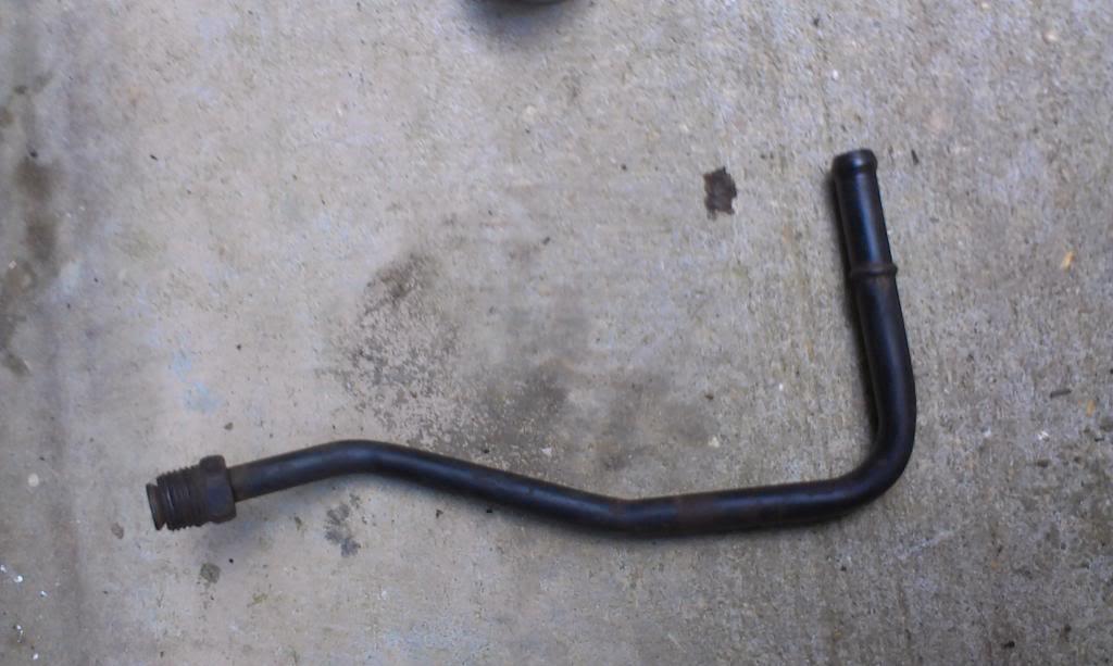
I was going to use this stock GM line to hook up my brake booster vacuum, but it wont work without a bunch of modifications.
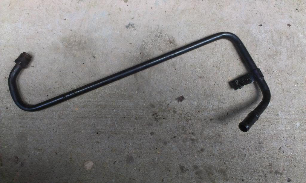
I need to buy an adapter for the throttle body, and this van unit will work. The tube size also matches the stock CJ rubber line size.
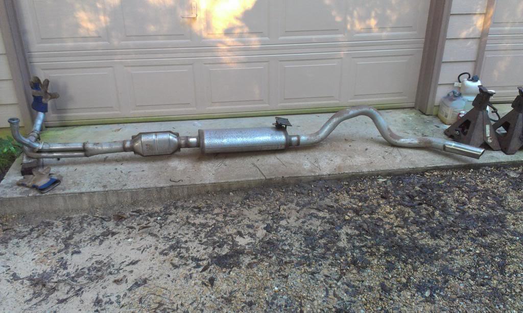
I also pulled the exhaust. It is all new, installed by the previous owner. Curious to what it will sound like??
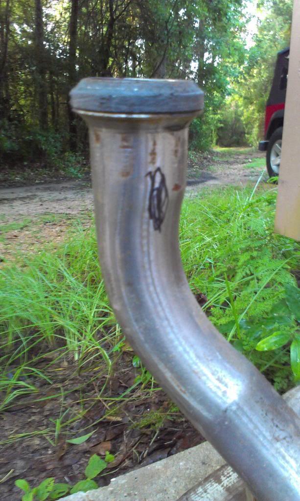
I am going to get an O2 sensor bung welded on the down pipe, driver side, should be convenient.
Pretty open over here.
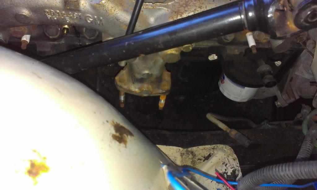
Finally started on the wiring. I pretty much knocked out the passenger side TBI/Start/Charge wiring.
First picture shows my starter. Big post is + battery side, little post is "start".
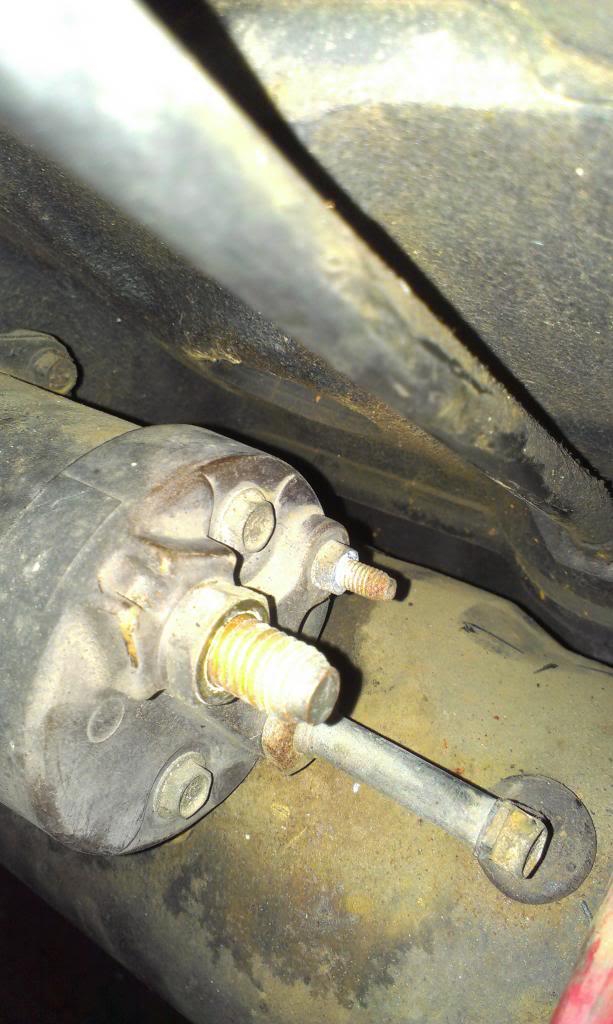
I am going to use the big + post on the starter as my main hot junction, for now. I will probably move my main hot lug to a remote location. Big + has charge wire from alternator, hot wires to fuse panel, and the alt remote sensing wire. On the "start" post, big purple wire is from Jeep to starter, little wire is from TBI harness, I presume for power on when starting.
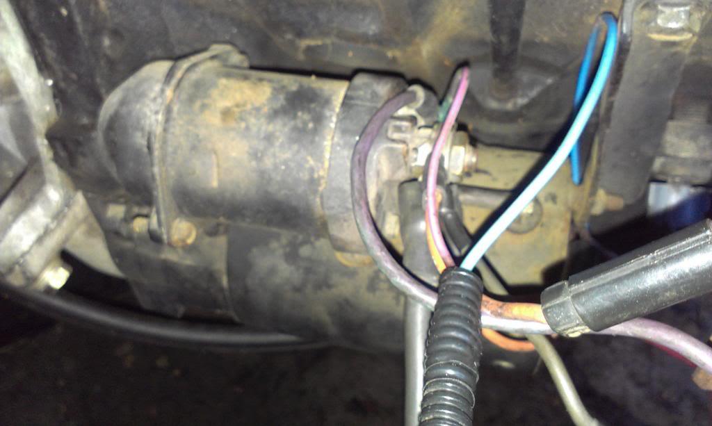
The knock sensor wire also goes through this area, blue wire.
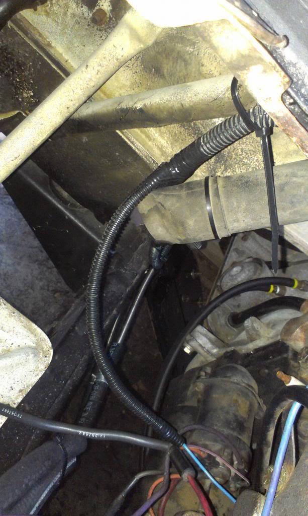
The fuel pump wires also go through the above harness. Does not look like much, and pictures are bad, but it took awhile to get it how I wanted it. It is fairly neat and orderly, with good, heat shrink crimps/connections where necessary.
The battery that came with the Scrambler still holds a perfect charge. It has sat at least 2 years since I have owned it. The smaller red wire is the harness constant hot, the small black is the fuel pump ground. I will connect them directly to the battery posts. The harness hot is fuse connected. The big purple goes to the Jeep harness "starter start" wire, the two reds are constant hots.
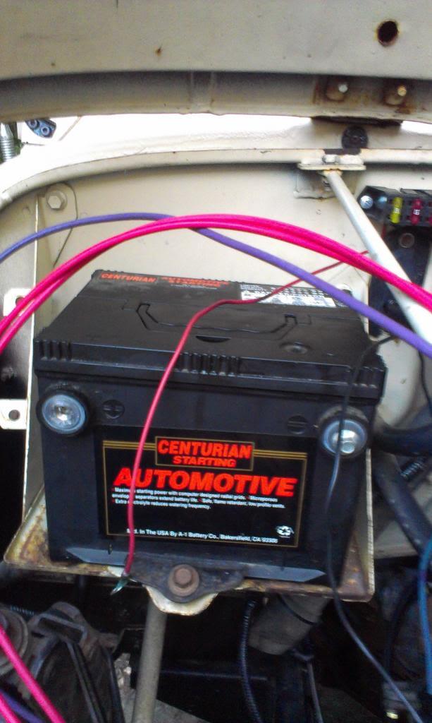
Slowly getting there........
That's it for now.
I was going to use this stock GM line to hook up my brake booster vacuum, but it wont work without a bunch of modifications.
I need to buy an adapter for the throttle body, and this van unit will work. The tube size also matches the stock CJ rubber line size.
I also pulled the exhaust. It is all new, installed by the previous owner. Curious to what it will sound like??
I am going to get an O2 sensor bung welded on the down pipe, driver side, should be convenient.
Pretty open over here.
Finally started on the wiring. I pretty much knocked out the passenger side TBI/Start/Charge wiring.
First picture shows my starter. Big post is + battery side, little post is "start".
I am going to use the big + post on the starter as my main hot junction, for now. I will probably move my main hot lug to a remote location. Big + has charge wire from alternator, hot wires to fuse panel, and the alt remote sensing wire. On the "start" post, big purple wire is from Jeep to starter, little wire is from TBI harness, I presume for power on when starting.
The knock sensor wire also goes through this area, blue wire.
The fuel pump wires also go through the above harness. Does not look like much, and pictures are bad, but it took awhile to get it how I wanted it. It is fairly neat and orderly, with good, heat shrink crimps/connections where necessary.
The battery that came with the Scrambler still holds a perfect charge. It has sat at least 2 years since I have owned it. The smaller red wire is the harness constant hot, the small black is the fuel pump ground. I will connect them directly to the battery posts. The harness hot is fuse connected. The big purple goes to the Jeep harness "starter start" wire, the two reds are constant hots.
Slowly getting there........
That's it for now.

SeeJayAte
CJ-8 Member
- City
- Greenfield
- State
- In
Slowly getting there........
You're getting there there a whole lot faster than I could Raymond!
 In the engines pics when you where working on the TBI, it looks like the HEI dist. sits fairly close to the firewall. If you have time, could you possibly measure from the back of the dist. cap to the firewall? I've currently got my old engine out and am trying to decide which engine mounts to use to get the new engine a couple of inches back towards the firewall. I measured before pulling the old engine and had just over 4 inches clearance. The front of the engine was pretty cramped even with a short water pump so I'd like to move everything back 2" or more if I can. Here's an old pic I took before pulling the engine:
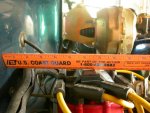 Thanks and keep up the great posts.
Last edited:
- City
- Biloxi
- State
- MS
You're getting there there a whole lot faster than I could Raymond!
No problem
I will take a picture tonight and post it up here tomorrow. My distributor sits close, I am running a "small cap", i.e. no coil in the cap. There is just enough room to pull the distributor out/spin the oil pump with a drill
- City
- Biloxi
- State
- MS
I had to work from Friday night, 7pm, until Saturday morning, 5:30am, plus rain Sunday, got some work done, still not running, though.
I kind of "jumped" around with regards to what I was working on, finishing up loose ends. So, the order of work might not make sense, but here goes.
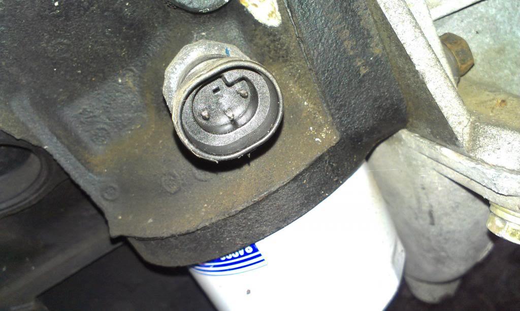
Quick picture of the oil pressure sensor. I wired it up as a two wire, did not use the idiot light wire. It works, more on that later.
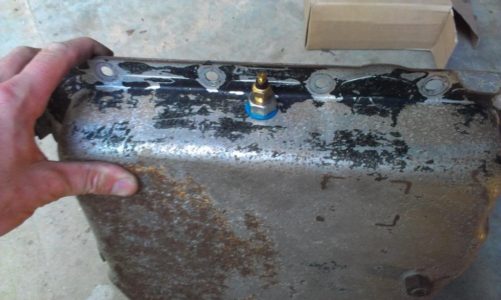
I dropped the transmission pan to install a temp sensor. I had to mount the sensor on the driver side. I could not mount it in the back, interference with internal components, and could not mount it on the passenger side, due to front driveshaft clearance issues. A few pictures.

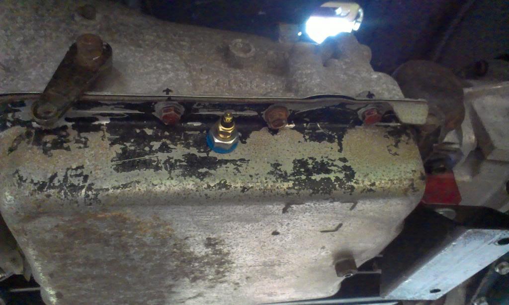
The transmission shifter stuff does mount on this side, but I think I can make this work.
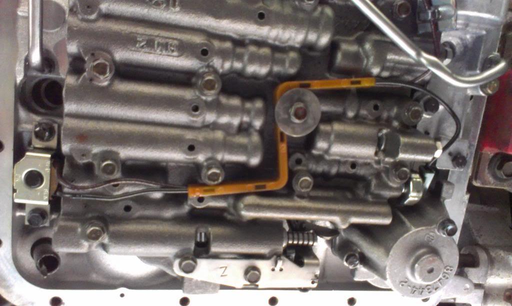
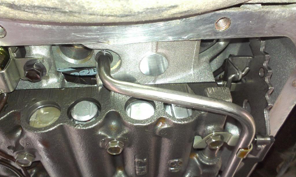
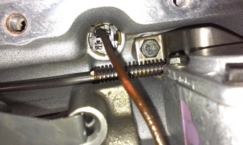
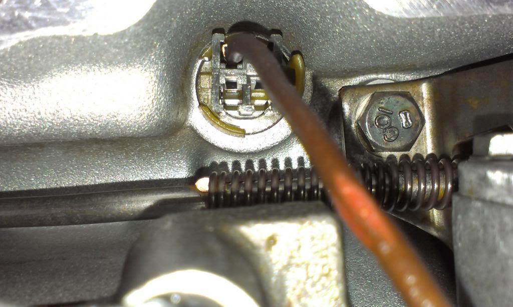
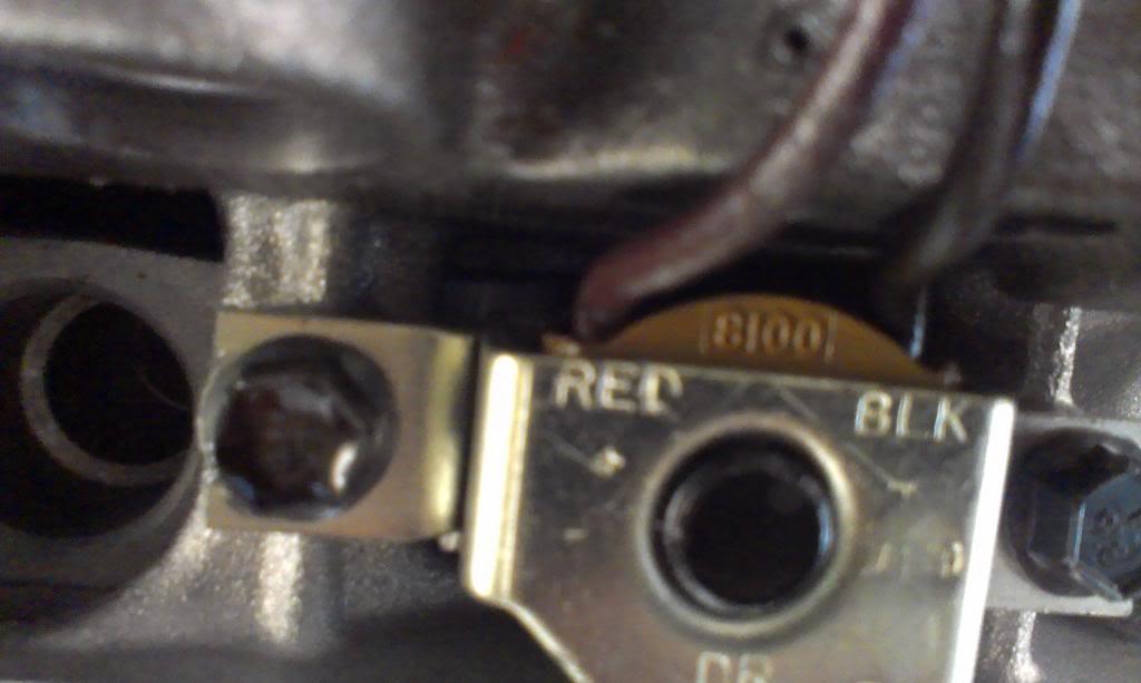
A few pictures of the transmission internals. I took these pictures so I can identify exactly what kind of set up I have. Even though the TCC has a 3 wire plug, only one wire is hooked up internally.
To help me figure out the automatic transmission stuff, I bought these two manuals:
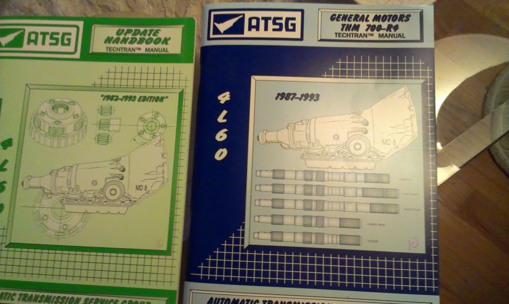
I briefly looked through these two books, lots of information. There are about 20 different ways these transmission came wired from the factory, including my one wire set up. According to the book, the one wire set up is correct for a CA truck model with a 5.7 engine. The best thing about it, though, IT IS WIRED LIKE A CANADIAN COP CAR, TOO, EHHHHHHHHHHHHHHHHHHHHHHHHHHHHHHHHHHHHHHHHHHH!!!!!!!!!!!!!!!!!!!!
I kind of "jumped" around with regards to what I was working on, finishing up loose ends. So, the order of work might not make sense, but here goes.
Quick picture of the oil pressure sensor. I wired it up as a two wire, did not use the idiot light wire. It works, more on that later.
I dropped the transmission pan to install a temp sensor. I had to mount the sensor on the driver side. I could not mount it in the back, interference with internal components, and could not mount it on the passenger side, due to front driveshaft clearance issues. A few pictures.
The transmission shifter stuff does mount on this side, but I think I can make this work.
A few pictures of the transmission internals. I took these pictures so I can identify exactly what kind of set up I have. Even though the TCC has a 3 wire plug, only one wire is hooked up internally.
To help me figure out the automatic transmission stuff, I bought these two manuals:
I briefly looked through these two books, lots of information. There are about 20 different ways these transmission came wired from the factory, including my one wire set up. According to the book, the one wire set up is correct for a CA truck model with a 5.7 engine. The best thing about it, though, IT IS WIRED LIKE A CANADIAN COP CAR, TOO, EHHHHHHHHHHHHHHHHHHHHHHHHHHHHHHHHHHHHHHHHHHH!!!!!!!!!!!!!!!!!!!!