• Notice for iPhone users: DO NOT use the image size reduction option when uploading photos to the forum. This causes portrait images to post as landscape. We have added a warning to the image insert pop-up as well.

Meet Rusty, 82 5.0 Build

That looks like it hangs down farther than I would have thought it would. Is that just because of how tall the M5 tranny is? Did you measure the tilt angle of the engine to tranny assembly? And, I can't remember... did you have a body lift at all?
No I did not measure it. I was waiting for my driveshaft to be done and when I was installing them I noticed the tranny was leaking from the adapter to the transfer case. Since I was going to remove it again, I decided to get a thicker skid plate. The transmission is currently sitting on the f150 trans mount bolted to the original skid plate. What angle should it be between the engine to transmission? And what is the recommended angle of each driveshafts. There is no body lift but it does have a 2.5 inch lift.

 
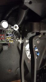
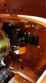
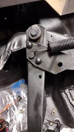
Installed the F150 hydraulic clutch reservoir. I drilled a 5/16 hole in the clutch pedal and used some plastic and nylon shims to keep it smooth.
 

Attachments

  • IMG_20211129_211929012.jpg
    IMG_20211129_211929012.jpg
    75 KB · Views: 26
  • IMG_20211129_212106463.jpg
    IMG_20211129_212106463.jpg
    86.6 KB · Views: 26
Here is the location of the hole that was drilled in the pedal.
 

Attachments

  • IMG_20211129_203007406.jpg
    IMG_20211129_203007406.jpg
    117.2 KB · Views: 11
No I did not measure it. I was waiting for my driveshaft to be done and when I was installing them I noticed the tranny was leaking from the adapter to the transfer case. Since I was going to remove it again, I decided to get a thicker skid plate. The transmission is currently sitting on the f150 trans mount bolted to the original skid plate. What angle should it be between the engine to transmission? And what is the recommended angle of each driveshafts. There is no body lift but it does have a 2.5 inch lift.

I set my engine/tranny at about 2 degrees (lower to the rear) when the frame rails were level. I'm not sure the angle here is critical (within reason, I'd say anywhere between 0 and 5 degrees). You just want to be sure you have proper clearance for everything around the motor (firewall, radiator, hood, exhaust, etc.).

For driveline angle, it looks like you have a standard 2-joint shaft. If that's correct, then you should be able to run angles up to about 15 degrees (although, if you are over 10 degrees, I'd consider switching to a CV shaft). The second part, for a 2-joint shaft, is that you want your rear t-case output and your rear pinion angle to be nearly parallel. When I ran a 2 joint shaft, I set my pinion to be about 1-3 degrees lower than the tranny so that, under load, they would be closer to parallel - this worked well for me.

Tom Woods (4xshaft.com) has some great tech articles relating to drivelines, if you are interested.
 
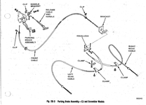
Anyone have a E brake diagram to share. I went to install mine and I don't think it should sag down so much.

I made the mistake when I bought the jeep to go out and buy what I thought was everything I needed.

All of these parts just sat in boxes for over a year. As I started opening boxes, that I cant return, did I realize I bought 2 of some parts, the wrong parts, parts I no longer need because I have gone in a different direction.
 
Never mind, I looked at my old passenger side e-brake cable and need to transfer the bracket over to the new cable.
 
Never mind, I looked at my old passenger side e-brake cable and need to transfer the bracket over to the new cable.
Is that the V shaped bracket that attaches to the underside of the tub? I'm going to try and tackle the e-brake installation this weekend and want to make sure I have the right brackets from the old trashed setup.
 
Found this...https://oljeep.com/gw/82_tsm/Part%202%20Section%20G.pdf

Here's the diagram from that in case that link ever breaks...
1639581774811.png
 
Is that the V shaped bracket that attaches to the underside of the tub? I'm going to try and tackle the e-brake installation this weekend and want to make sure I have the right brackets from the old trashed setup.
yes, once you run the rear cables thru the frame section you would then use that bracket to keep the passenger side cable from hitting the differential. You will need 4 clips total. Can send pics if needed.
 
yes, once you run the rear cables thru the frame section you would then use that bracket to keep the passenger side cable from hitting the differential. You will need 4 clips total. Can send pics if needed.
If you don't mind snapping a few that'd be great.
 
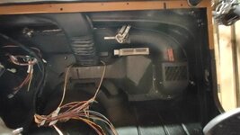
Finally got the heater rebuilt and installed. Went with the Blazer motor with fan and a new aluminum heater core. Also need to create a bracket to hold the computer for the front harness. Installing the gauges in the dash. Pics soon, just missing a few nuts.
 

Attachments

  • 1646022539965658003513757398798.jpg
    1646022539965658003513757398798.jpg
    83.3 KB · Views: 22
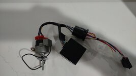
I added the intermittent wiper delay, but does anyone have a schematic of where the black box mounts?
 

Attachments

  • 16460233410677145096219745178994.jpg
    16460233410677145096219745178994.jpg
    45.4 KB · Views: 11
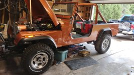
Finally put the Indy Mags on after 6 months in the box. Still working on wiring the fuel injection, dash and running the fuel lines. Very motivated to get it running again.
 

Attachments

  • IMG_20220625_144723504.jpg
    IMG_20220625_144723504.jpg
    144.1 KB · Views: 18
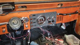
Added the tach but no clock. M5od trans and the wiring for the computer hanging in the far right.
 

Attachments

  • 16561911546935826024012544521168.jpg
    16561911546935826024012544521168.jpg
    144.4 KB · Views: 13
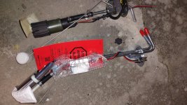
Wanted to share this in-tank fuel pump and sending unit setup I am using. It's a Delphi pump sender for a late 80's model Bronco. It has the same 2inch base. I just shortened the tube at the pump about 4.5 inches. The sending unit at the top was my pisspoor attempt at using an Omix unit and attaching a pump to the bottom.
 

Attachments

  • IMG_20220716_172041969.jpg
    IMG_20220716_172041969.jpg
    156.3 KB · Views: 18
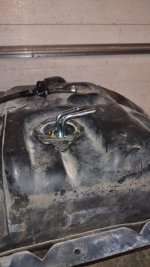
Now I can use quick connects from the engine to the tank.
 

Attachments

  • IMG_20220716_210259613.jpg
    IMG_20220716_210259613.jpg
    102.8 KB · Views: 16
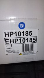
Part # Delphi unit.
 

Attachments

  • IMG_20220716_210310568.jpg
    IMG_20220716_210310568.jpg
    65.7 KB · Views: 6
That looks like a great option for a fuel pump. I suppose all it is missing is the little baffled area to hold fuel at angles. Probably not a big deal with that big poly tank.
 
What is the ohm range for the sending unit?

Jeep generally used the dodge sending units. I thought Ford was more in line with GM values.
 
Ok I am stumped, the fuel sending unit / electric pump is rated to 36 PSI but it is only putting out 7 PSI at the fuel rail. I have 5/16 nylon tubing running from the pump to the new filter to the engine with 5/16 as a return line as well. I really don't want to drop the tank but I don't think I have a choice. I can get the engine to run when I spray starter fluid down the throttle body. There are no kinked or squeezed lines. Again this is a sending unit from a 1989 full size bronco being used for a 95 Mustang GT.
 
Back
Top