• Notice for iPhone users: DO NOT use the image size reduction option when uploading photos to the forum. This causes portrait images to post as landscape. We have added a warning to the image insert pop-up as well.

Spankrjs' 1984 Long Term Project

Small update.

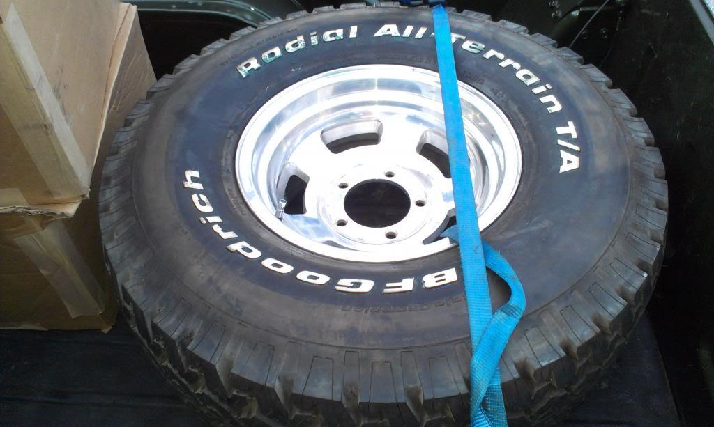
I was able to get the fourth wheel/tire assembled, and it is leak free:D I now have four tire/wheel assemblies ready to go, just need a spare tire now.

IMAG0683_zpsb328291a-1.jpg


I am going to try to clean/paint/inspect/ and hopefully just re-seal the transfer case this weekend. Once it is installed, I can install the tire/wheels, torque all the suspension bolts/u-bolts down, and then get started on the last big obstacle - engine wiring/plumbing.

That's it for now:wave:
 
I finally started on the transfer case disassembly/cleaning/inspection.

The first thing I did, trip to the steam cleaner. The case/parts cleaned up great.


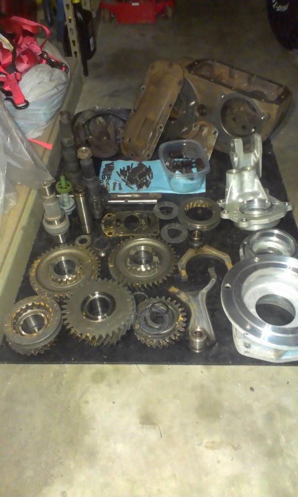
After the steam cleaning, I started taking the transfer case apart. The picture does not show it, but the front output housing, shift forks, shift rails, intermediate gear, front input, and the adapter housing all came off with no fuss.


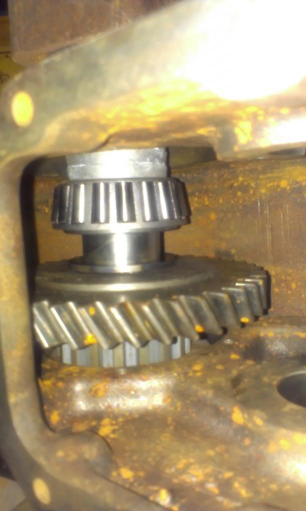
And now, for the problem. I have rebuilt three Dana 300 transfer cases, and have never ran into this problem. The rear output housing is stuck. I used a large, two jaw puller, and actually broke the aluminum flange. I tried to drive the shaft out, and all I managed to do was destroy the nut.


I have a spare rear housing, so no big deal. But, I still don't like breaking stuff. I am scared of pressing the shaft out, I do not think I can get something large enough around the "pressed on the rear output shaft" gear, to support the inside of the case, to allow me to press the shaft through. Right now, by hammering on the output shaft, I am actually driving the output shaft off of the pressed on gear fit, NOT loosening the inner bearing. The one thing I do not want to do is crack the case. So, since the aluminum rear output housing is already broke, I am going to cut it into pieces to remove it. Once I get it off, I can see what is going on inside. Maybe somebody installed the inner bearing backwards, not sure, but something is messed up obviously:shrug:

Worst case scenario, I will cut the output shaft in half. Then, time to upgrade to HD rear output. I do not want to have to do this, but I would rather sacrifice the rear output shaft before busting the case.

That's it for now.
 
That's a new one on me...

Yep, I have no idea:shrug:

Once/if I get it apart, the problem will hopefully be obvious. It is almost like they did not shim the output shaft, and the outer bearing is seized on the shaft, but for now that is pure speculation:shrug:
 
I finished tearing the transfer case to pieces, which ended up being an expensive process.

I was able to finally drive the rear output shaft out of the housing. Note the damage to the face of the nut/shaft.


I was unable to turn the nut back off, so I had to drill two holes in it, 180 degrees apart, then bust it in half with a chisel.


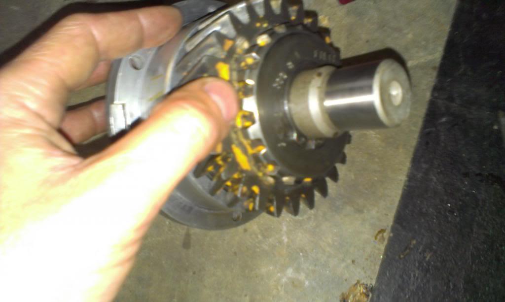
And this shaft is destroyed. Look at how the threaded end mushroomed.


I might be able to have the end of this shaft machined back down and re-threaded, maybe, but even then, I don't know how much I would trust it behind a V8.

Well, no since crying about it. Since I have a V8, 33's, and a rear locker, might as well upgrade!! I have broken a stock Dana 20 rear output with a V8/33's/Detroit Locker, no reason to think I wouldn't do the same with a stock Dana 300 output. I was going to order the JB Conversions HD output, but they are out of stock till August. So, i ordered an Advance Adapters HD rear output kit, plus a complete Dana 300 rebuild kit. Might as well go all the way. Hopefully the parts will arrive in time so I can rebuild the transfer case this weekend.

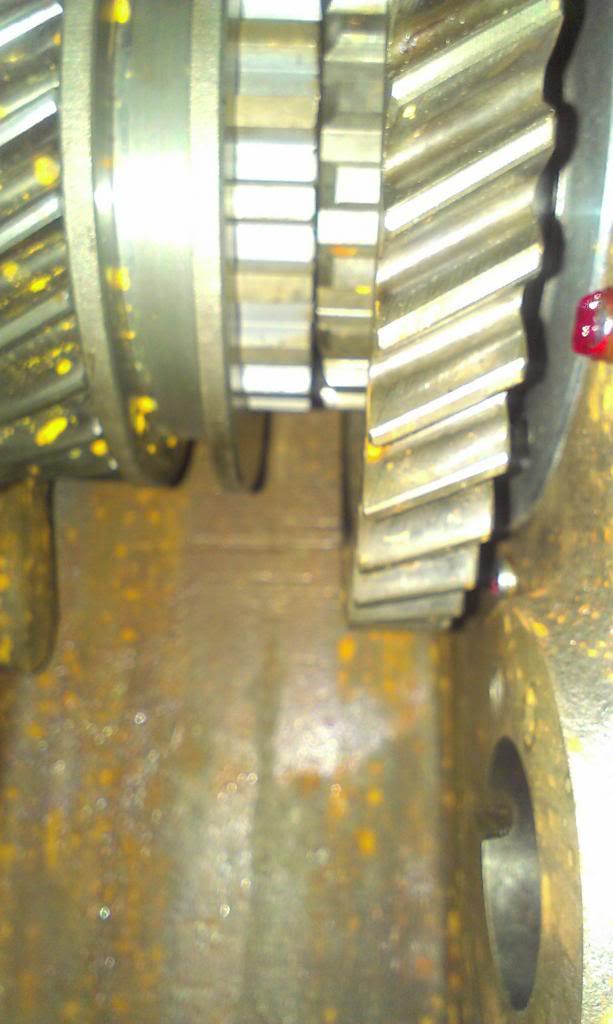
When I finally removed the stock rear output shaft, there were no shims present. The outer bearing was "froze" to the shaft. The two output shaft bearings are galled/binding/feel rough. The input shaft ball bearing also feels like crap. So, a full rebuild is a good idea. I would rather fix it now, then have it blow up on the highway some where.

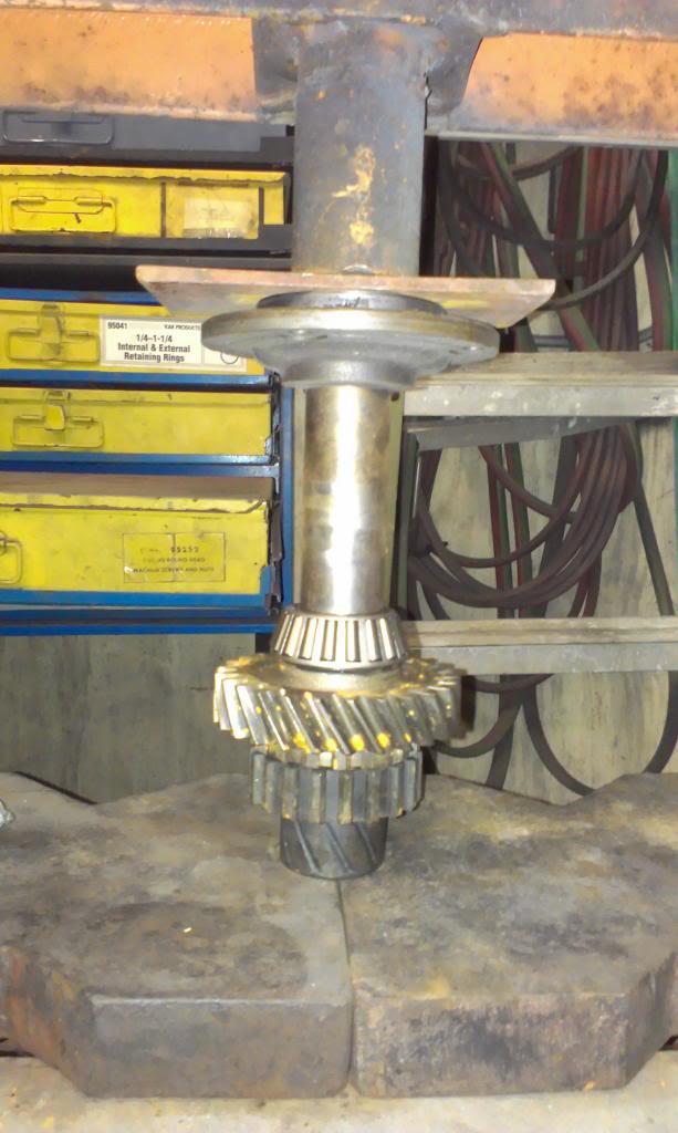
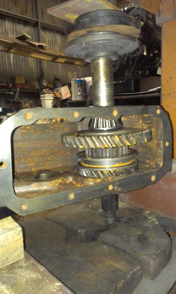
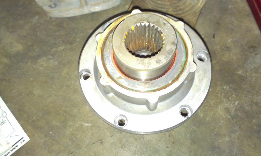
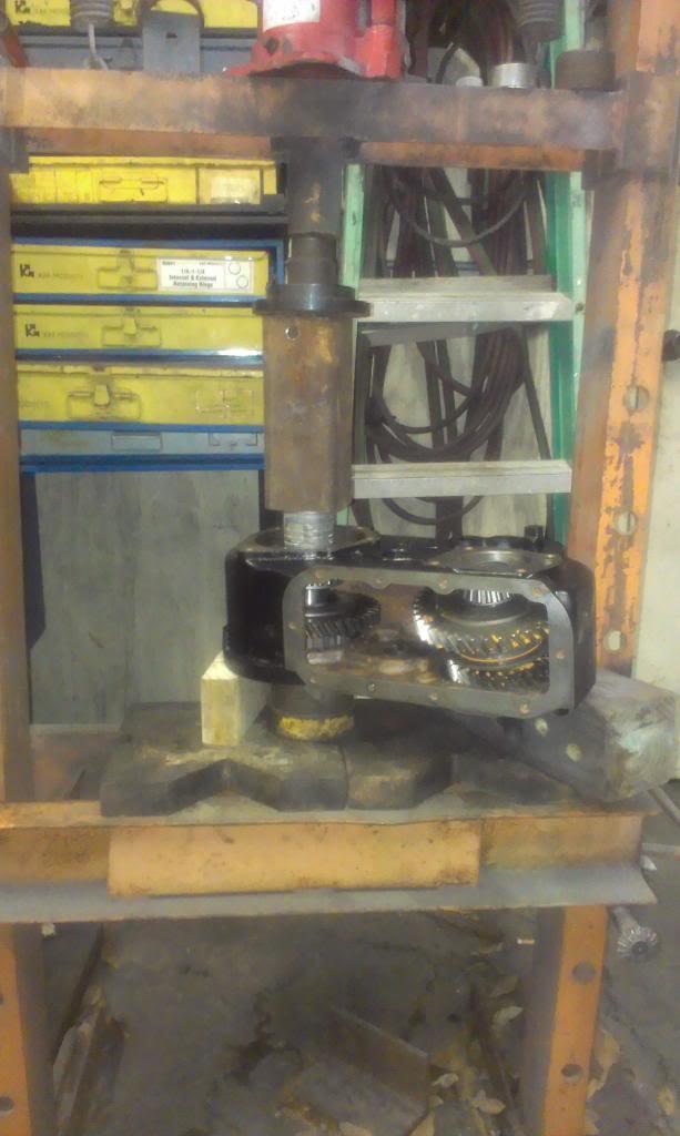
After licking my wounds, I took the case to the press and removed the rest of the parts. These are the parts that require a press to disassemble.


Input shaft and bearing.


Rear output shaft/gear/inner bearing.


And the front output/associated gears/bearings.


I plan on cleaning all the parts, and repainting the case in the next few days. If my parts make it here by Friday, I should be able to get this Dana 300 back together this weekend.

That's it for now.
 
I did some more transfer case work. I was able to clean all the parts up, and besides the rear output shaft/housing, which will be replaced, everything else looks fine.

IMAG0708_zpsb73acc76-1.jpg


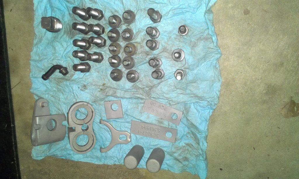
I also wire wheeled all the bolts clean, and my buddy sand blasted the other small parts.

IMAG0709_zps69d3dd1f-1.jpg


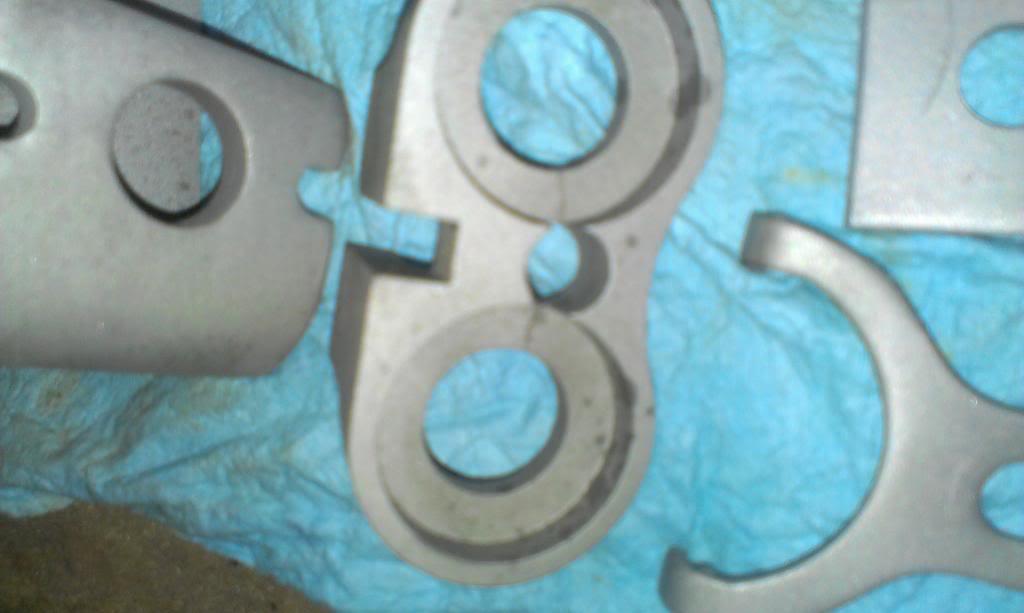
The only "damaged" part I found; the shift rail guide/seal protector has two small hairline cracks in it. I guess someone over tightened the retaining bolt?? It is not really an issue, should not cause any problems.

IMAG0710_zpsaff36275-1.jpg


I am going to try to get the case/parts painted tonight, and hopefully start reassembling Saturday, as long as my parts get here on Friday:fingerscrossed:

That's it for now:wave:
 
That shaft looks crazy!

Amazing what a 2 pound maul can do :eek::(

But, I still think I can get the "mushroomed" end turned back down, then re thread the shaft. The damage is only at the very end of the shaft, not the threaded part where the nut is actually tightened down to, should be OK for a spare shaft:shrug:

It will probably still be better then any of the crappy "replacement/made in China out of pot metal" shafts that are available :rotfl::thumbsup:
 
I might have a spare, but I'm leaving town for a week, so I wouldn't be able to get to it for a while.
 
Amazing what a 2 pound maul can do :eek::(

But, I still think I can get the "mushroomed" end turned back down, then re thread the shaft. The damage is only at the very end of the shaft, not the threaded part where the nut is actually tightened down to, should be OK for a spare shaft:shrug:

It will probably still be better then any of the crappy "replacement/made in China out of pot metal" shafts that are available :rotfl::thumbsup:

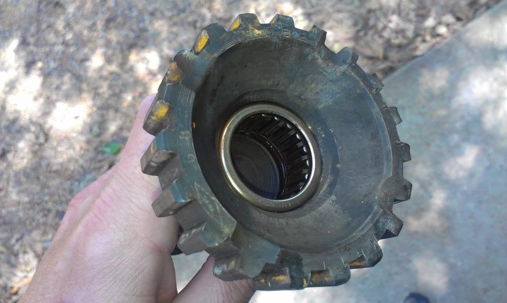
Am I seeing things or is the opposite end of the output shaft munched in that one picture? He edge with the fat teeth looks like large chunks are missing.
 
I appreciate it, but I just found a spare retainer in my "Dana 300 junk box":cheers::thumbsup:
 
Am I seeing things or is the opposite end of the output shaft munched in that one picture? He edge with the fat teeth looks like large chunks are missing.

The input shaft is 100% perfect. The inner portion of the output shaft does have some "machined notches":

IMAG0723_zpsfd8f8c42-1.jpg


Not sure if this is what you are referring to, but it was made this way, maybe "oiling slots":shrug:
 
My Advance Adapter rear output shaft DID NOT show up Friday, so I was not able to complete the Dana 300 reassembly.

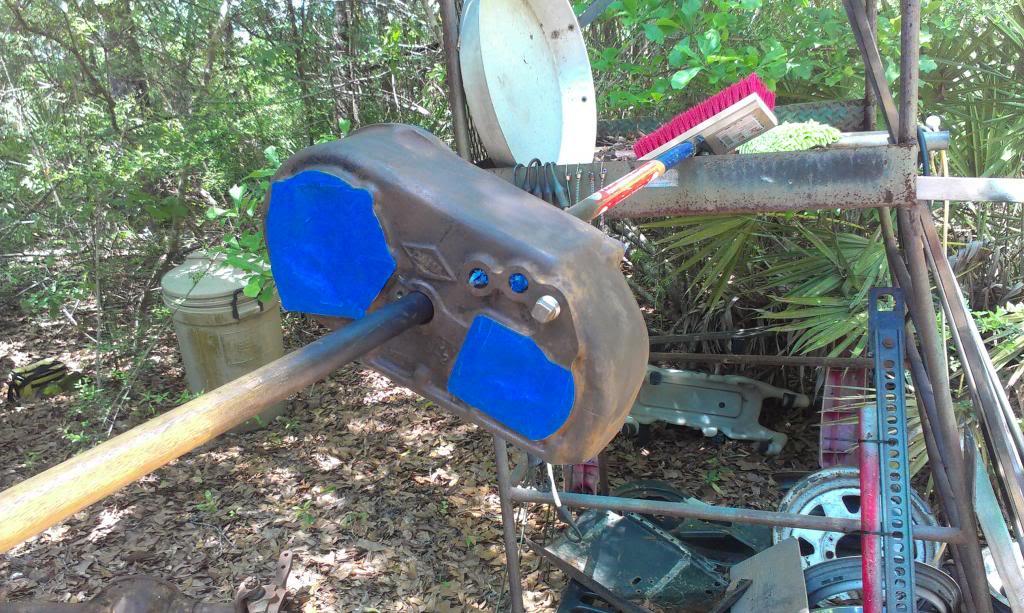
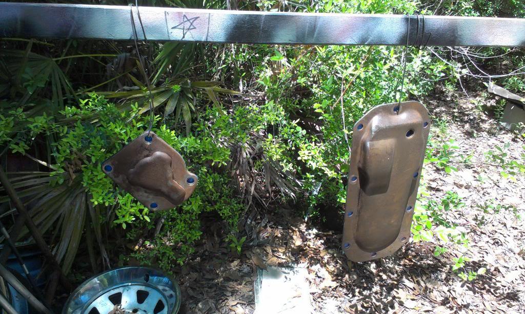
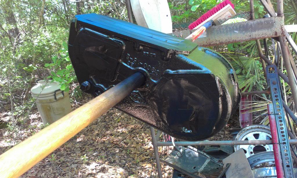
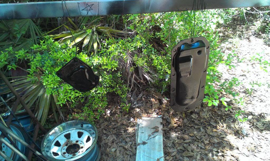
But, I was able to start on it. I prepped the case, front input shaft rear bearing retainer, and the inspection cover.

IMAG0712_zpsb8b30990-1.jpg


IMAG0713_zps98dc0ef1-1.jpg


I did not prime them, I applied some VHT Chassis and roll bar paint directly to the case/parts. This paint will adhere well to clean metal, and without a primer coat, it seems to be more chip resistant.

IMAG0714_zps7347a8fc-1.jpg


IMAG0715_zps087acc20-1.jpg


I also wiped down the previously sand blasted small parts before paint.

IMAG0716_zps88c6160f-1.jpg


IMAG0717_zps0db409a6-1.jpg


I found some left over silver spray paint, so I sprayed the above smaller parts with it.

IMAG0718_zpse11e9a3e-1.jpg


IMAG0719_zps1069cb40-1.jpg


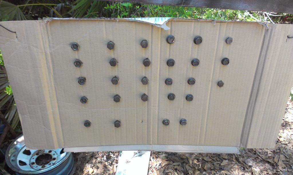
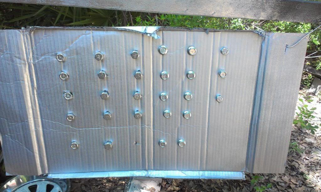
In keeping with my "bling-bling" silver spray paint theme, I decided to paint all the bolt heads, too. I applied the paint directly to the clean bolt heads, I guess I will find out if it survives the "wrench/socket" test???

IMAG0720_zpsb1129018-1.jpg


IMAG0721_zps20f742c0-1.jpg
 
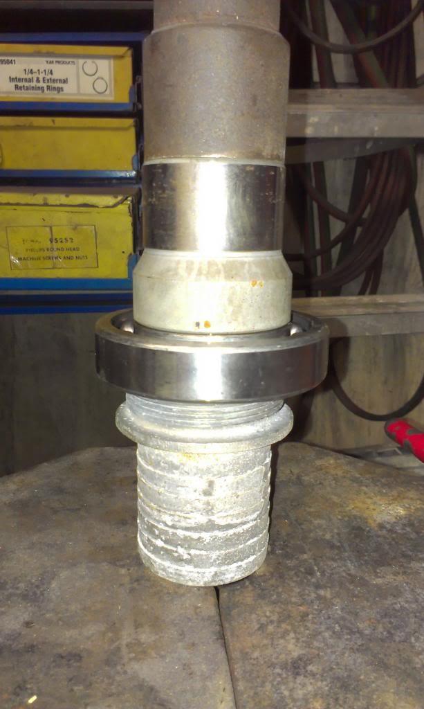
I also brought a few of the parts back to the shop at work to press on some bearings.

I used some type of random electrical conduit thingy to press on the input shaft bearing. You don't really have to use a press to put this bearing on, but it makes it easier. I ended up having to remove this bearing again, more on that later.

IMAG0724_zps7e9cab7e-1.jpg


Next, I found an old transmission input shaft bearing retainer that fit the front output shaft bearing perfectly, so I used it to press on the front bearing.

IMAG0725_zpse0e7b043-1.jpg


And this is the PIA one, the front output shaft rear bearing. You have to install the shaft/associated parts in the case before pressing this bearing on. A helper is useful for this step, but not necessary. I used the same transmission input shaft retainer to press this bearing on.

IMAG0726_zps66a410ab-1.jpg


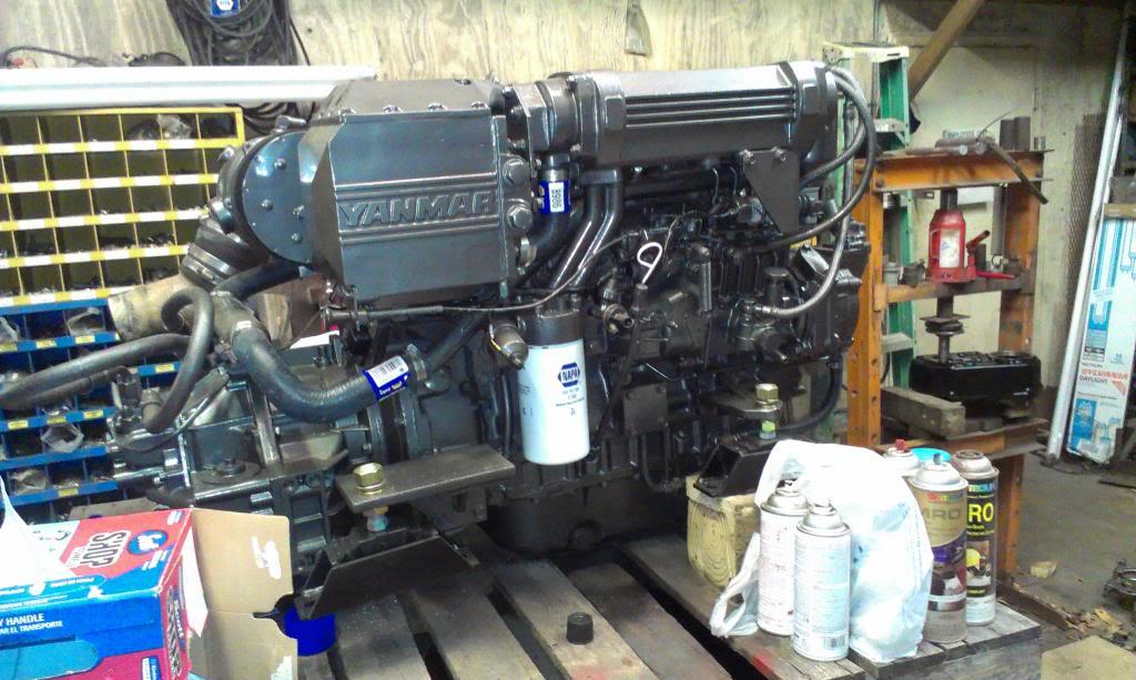
Next, I stripped off all the water cooling parts off this Yanmar Diesel, in preparation of swapping it in. Just kidding LOL.

IMAG0727_zpscb3f1867-1.jpg


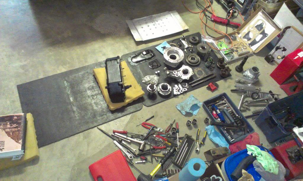
And back at home, lots of parts and tools thrown about, organized chaos LOL.

IMAG0728_zps3bf0c78f-1.jpg


Back to the input shaft bearing. When I got home, I assembled the input shaft/bearing assembly into its housing. When I checked the clearance between the input shaft gear and the retaining snap ring, it was way over the .003 MAXIMUM allowable clearance. So, I removed the bearing from the input shaft, installed some shims, and reassembled. I now have about .001 clearance, which should be great. As it was previously assembled, there was way too much play.

IMAG0729_zpsf010a8b5-1.jpg


One other interesting note. The FSM says to install the seal in the input shaft housing before installing the shaft. If you do it this way, it is about impossible to get the shaft through the seal without tearing it up. I assembled the shaft in the housing, then installed the seal. Seems to work better.

IMAG0730_zpsf12c0d09-1.jpg


I could have assembled the front output shaft side of the case on Sunday, but I slacked off instead.

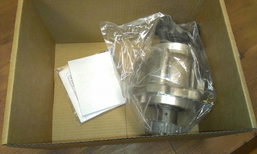
And today, the rear output shaft showed up.

IMAG0731_zpsefc8b81d-1.jpg


Hopefully, I can get this Dana 300 reassembled this week. This one step seems to really be kicking my butt/taking too much time.

That's it for now.
 
Took inspiration from your getting your 300 done. Installed the LoMax 4.1 kit. Glad I bought the Harbor Freight press last fall. Had similar issues with shims. Found this interesting. I miked all the new gears and the stock gears. None were the same. One of the kit gears was. 004 thicker than the one it replaced.

Also installed the Advanced Adapter for my 700r4. Now I have to figure out what I am going to install it in.

Thanks for the inspiration.
 
Took inspiration from your getting your 300 done. Installed the LoMax 4.1 kit. Glad I bought the Harbor Freight press last fall. Had similar issues with shims. Found this interesting. I miked all the new gears and the stock gears. None were the same. One of the kit gears was. 004 thicker than the one it replaced.

Also installed the Advanced Adapter for my 700r4. Now I have to figure out what I am going to install it in.

Thanks for the inspiration.


Glad I could help :thumbsup::cheers:
 
I finished up all the "press" work last night after work.

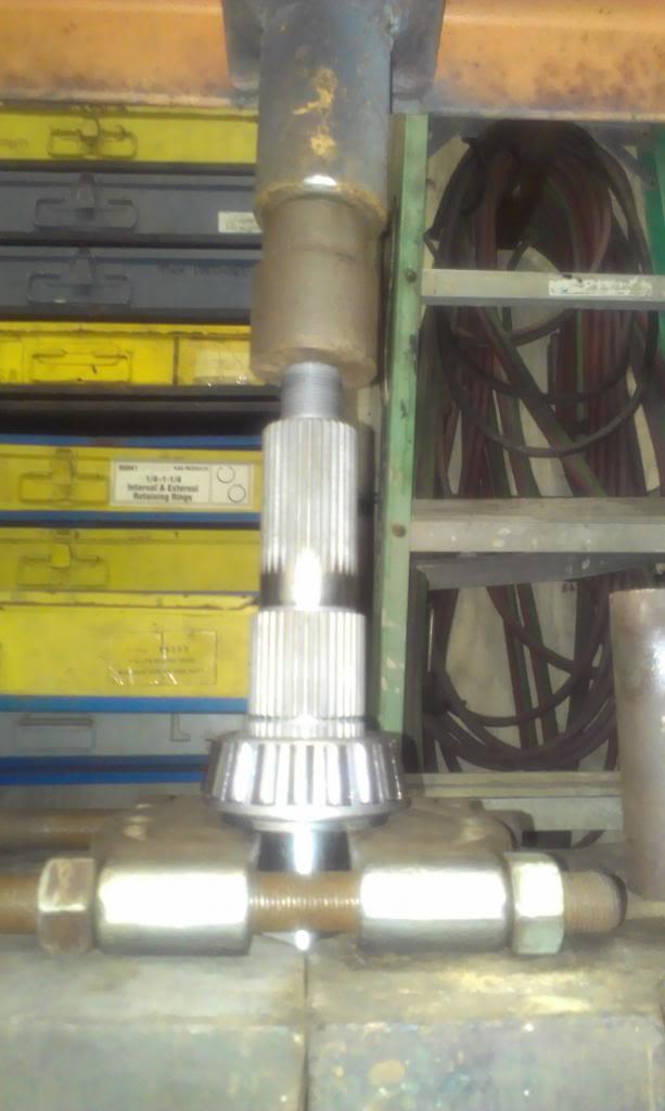
Pressing the new bearing off the new output shaft, in order to install the large gear.

IMAG0741_zpsddc172f6-1.jpg


The assembled rear output shaft/gear assembly, pressing the new bearing back on. Note the new thrust washer that must be used with this shaft, just below the bearing.

IMAG0744_zpsca7bcd69-1.jpg


IMAG0745_zps4a284fc4-1.jpg


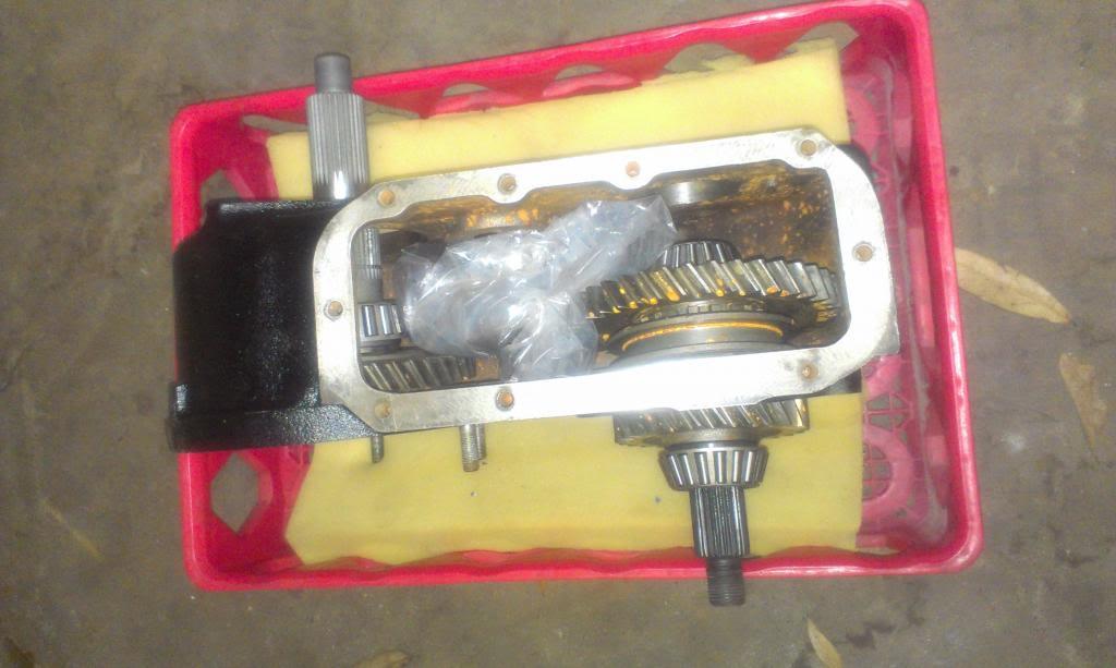
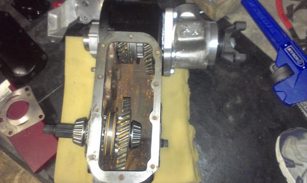
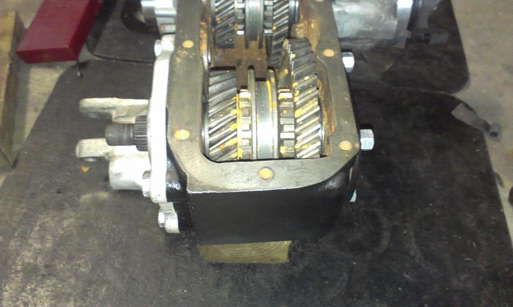
And the semi assembled transfer case. the balance of the parts left to install do not require any special tools, except for setting the end play on the front output shaft.

IMAG0746_zps07f3f0bf-1.jpg


That's it for now.
 
Still pecking away at the Dana 300 rebuild. I installed the AA HD rear output and the input shaft assembly. Funny thing is, I am using a Novak input shaft (700R4 adapter) with the Advance Adapter rear output shaft, but it all seems to work perfect.

A few "notes" from the install.

The speedo gear snap ring, speedo gear, and rear shim stack installed. The shim stack is actually a one piece machined washer. AA sets the end play before they send out the shaft, so no dial indicator needed. There is a slight chamfer on the shim stack, it must face the speedo gear.

IMAG0748_zps03a490f3-1.jpg


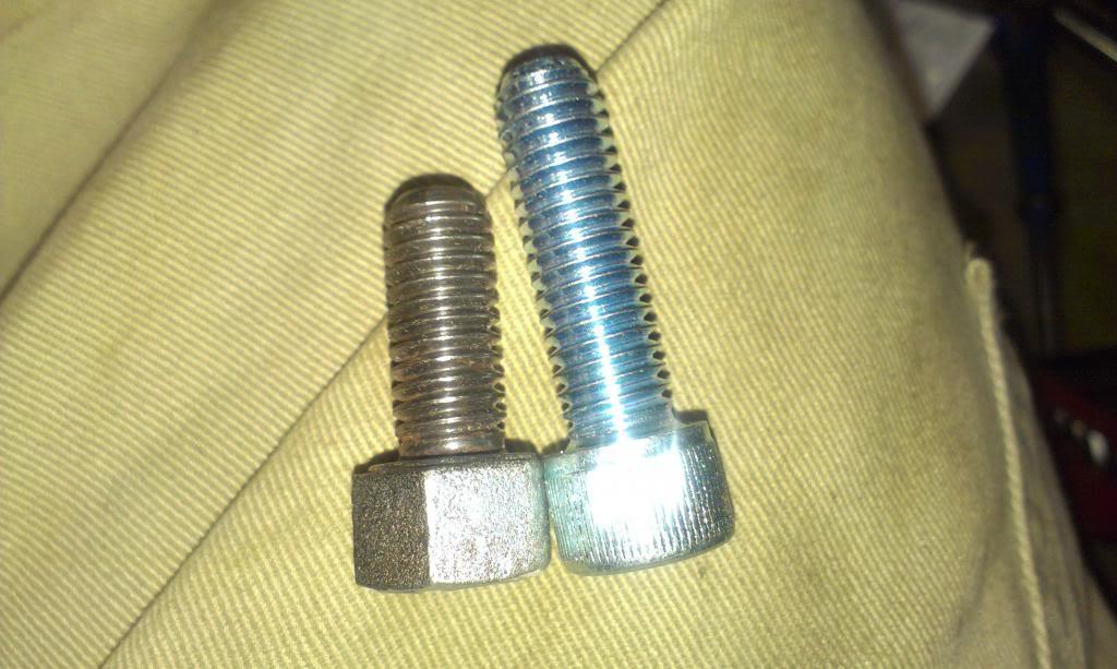
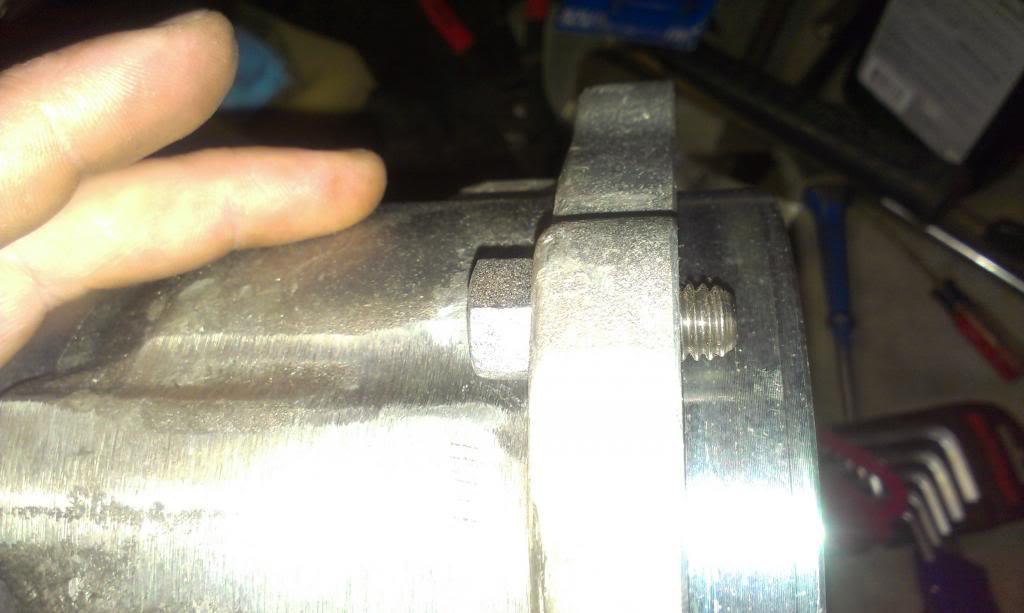
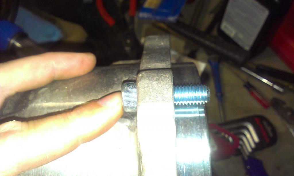
The output kit comes with new rear output shaft housing attaching bolts. The instructions say to reuse the stock ones, but the included longer bolts are needed.

IMAG0749_zpsa112a91b-1.jpg


IMAG0750_zpsf4f87e91-1.jpg


IMAG0751_zpsdcc1f212-1.jpg


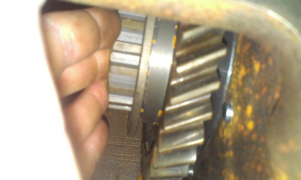
And a picture just to show that there is clearance between the longer bolts and the internal gear face, plenty of room.

IMAG0752_zps0e454d3a-1.jpg


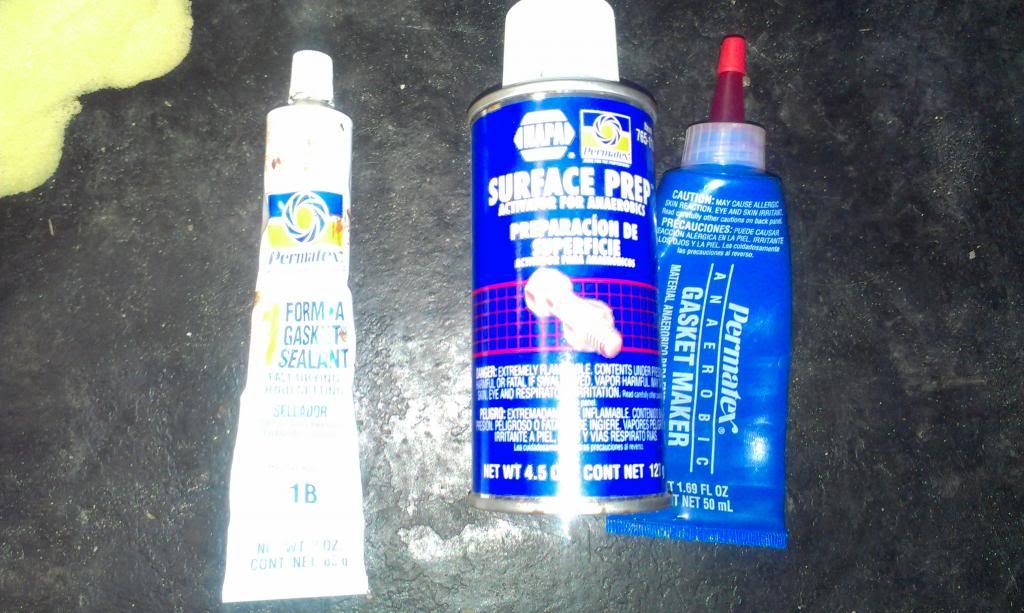
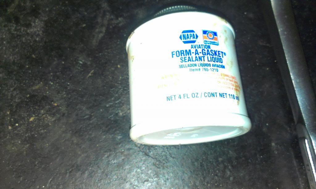
Quick picture of the sealants I am using. I use the stuff in the tube on the bolt threads. Since most of the threaded holes in the case go into the oil filled case, I always seal them to prevent seepage. This is a "hard" sealant, made for threaded connections. The stuff in the can is a primer for the anaerobic sealant in the tube. I use the anaerobic sealant to seal the aluminum housings to the cast iron case. I used the same products on my red Scrambler and Yard Scrambler, and so far, no leaks (knock on wood/fingers crossed).

IMAG0753_zps9f132fd4-1.jpg


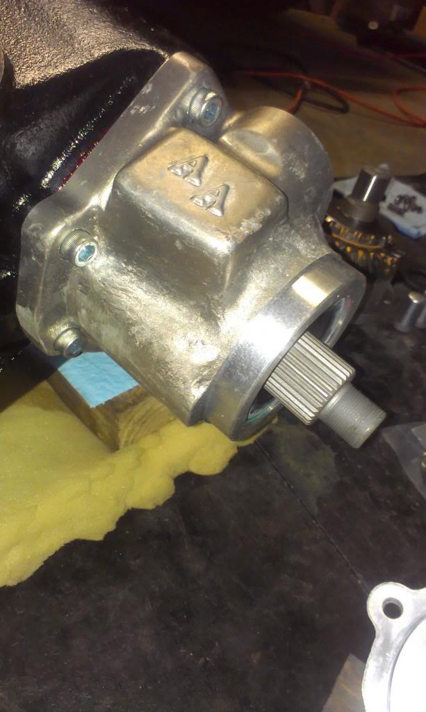
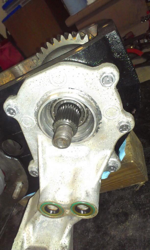
And the rear output shaft housing bolted on.

IMAG0754_zpsfa769205-1.jpg


Make sure you install the caged needle bearing inside the output shaft (factory installed by AA). Also, make sure you put on the shift collar before the next step.

IMAG0755_zps463a4272-1.jpg


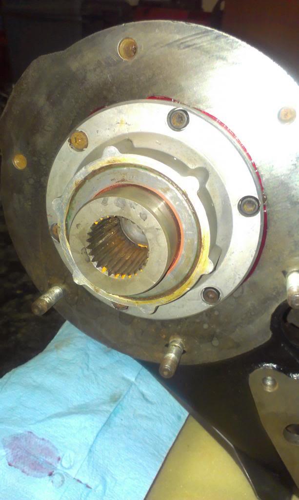
I bolted on the previously assembled front input shaft housing/shaft/bearing/gear next. You can see some of the anaerobic sealant that squeezed out around the edges, looks red.

IMAG0756_zps8ad5e084-1.jpg


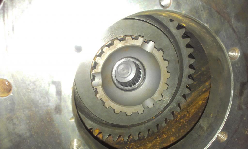
And what the assembled input shaft/rear output shaft look like on the inside. Note that the shift collar is in place, it is easy to leave this part out!!!!!!

IMAG0757_zps7b483705-1.jpg
 
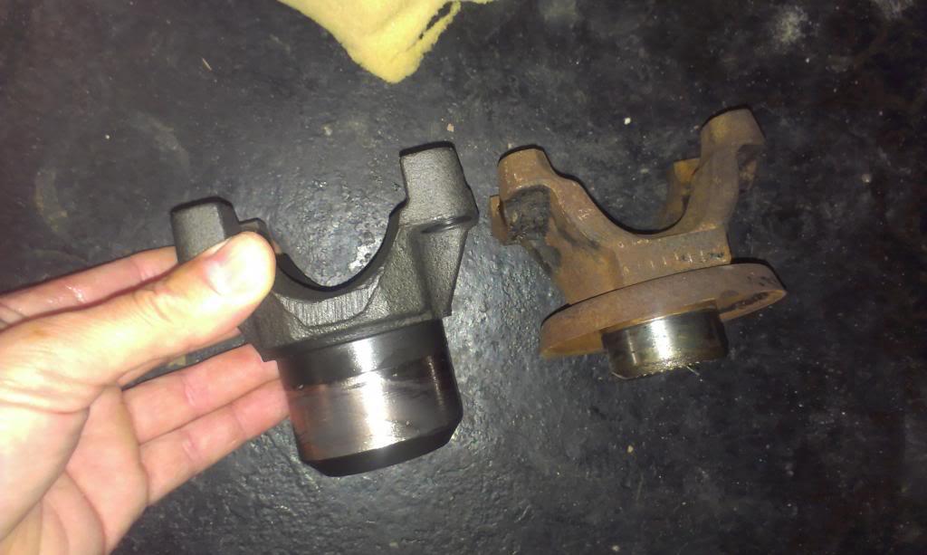
A quick picture showing the differences between the AA rear yoke and the stock one. The AA one seems way more beefy/stronger. I used the non-CV yoke, no need for a CV on this Scrambler.

IMAG0758_zps2ba80f74-1.jpg


Quick picture of the "yoke seal" included in the kit. This slides on inside the yoke, before installing the retaining nut. I usually apply some sealant to the output shaft splines before installing the yoke, but I am going to try this seal to see if it works.

IMAG0759_zps2573bc19-1.jpg


And the installed output shaft/input shaft assemblies.

IMAG0760_zpsab079608-1.jpg


So far, everything feels perfect. No "play" at the output, and everything turns nice and smooth.

Still to do:

install shift rails/associated parts in front output shaft bearing retainer
set front output shaft end play
install intermediate shaft
all the other little doo-dads

That's it for now.
 
I worked on the front output shaft last night, got a bit more done.

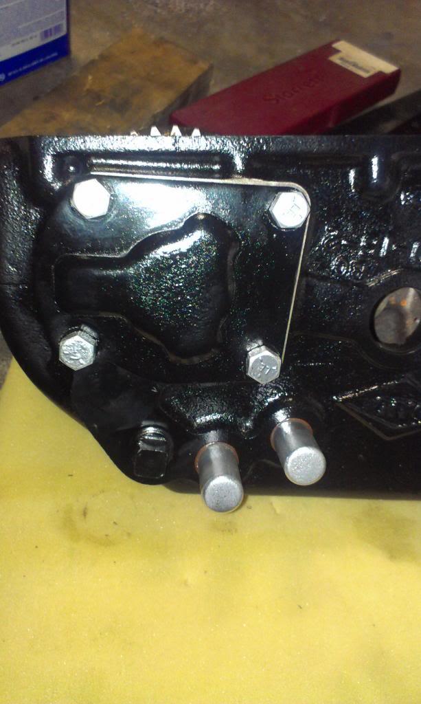
I installed the two shift rod thimbles, sealed them to the case with some of the hardening sealant. I also installed the rear bearing retainer plate with the original shim stack, as a starting point. Surprisingly, the paint I used on the bolt heads is holding up pretty good. I must have installed/removed these bolts about 20 times last night, while adjusting end play, and they still look pretty good.

IMAG0761_zpsd7adc89f-1.jpg


I then bolted on the front bearing retainer thing. I did not use any sealant at this time, on the front or the back, since I have to take things on and off to adjust the end play. I also did not have the front seal installed at this time.

IMAG0762_zpsd8dde373-1.jpg


Quick picture of what the assembled/bearing supported front output shaft looks like.

IMAG0763_zps46998686-1.jpg


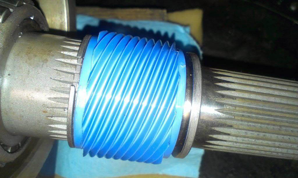
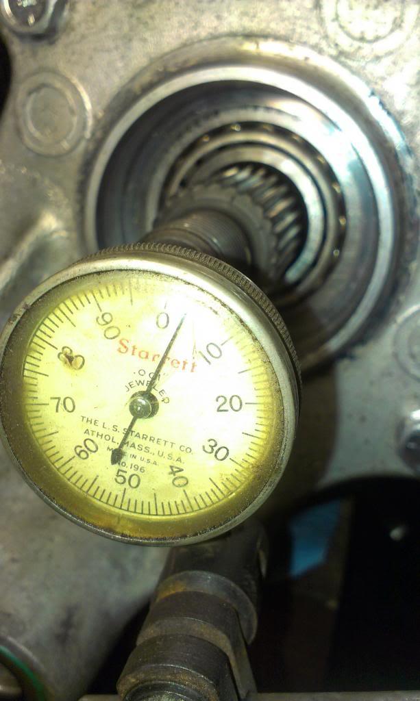
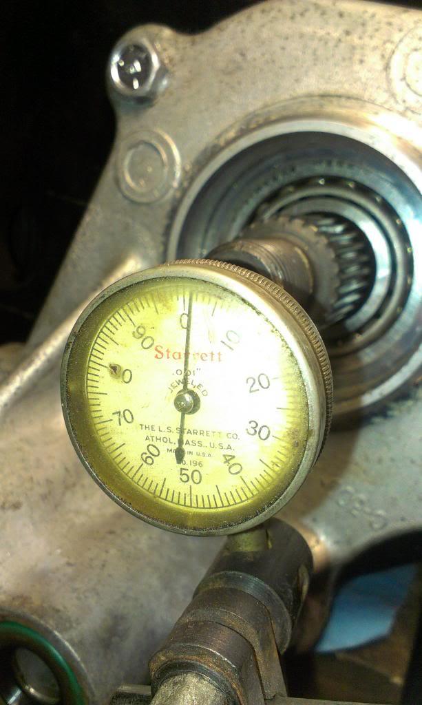
I added one super thin shim to the original shim stack, and had a reading of around .004-.005. This is within the factory recommended range of .001-.005, but it feels kind of loose with this much play IMO.

IMAG0766_zps1728c0dc-1.jpg


This is where it gets kind of tricky. The FSM, nor any other literature I have seen, ever recommends sealing the shim stacks together/to the case/to the bearing retainer plate. I always do, because I do not want leaks. So, this is what I do, don't know if it is "correct", but so far, it works for me.

First, I pulled out the super thin shim I added to the "presumed" factory shim stack.

IMAG0767_zpsbe6d04e7-1.jpg


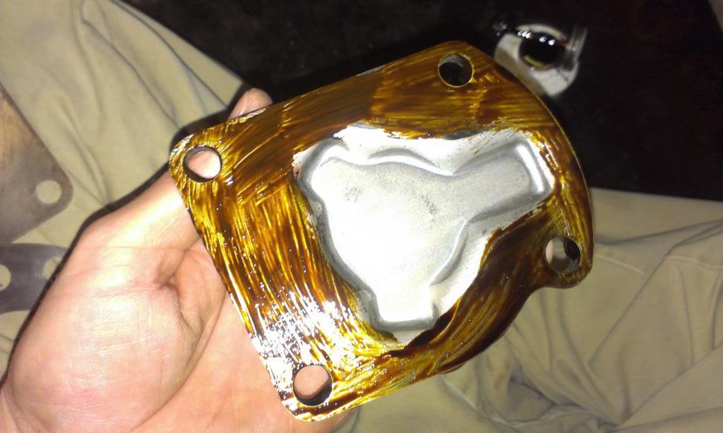
Next, I use the below pictured stuff to coat both sides of each shim, the face of the transfer case, and the face of the retaining plate. Basically, I "glue/seal" the shims, retaining plate, and transfer case together.

IMAG0770_zpscb3d4e29-1.jpg


IMAG0771_zps03ee978c-1.jpg


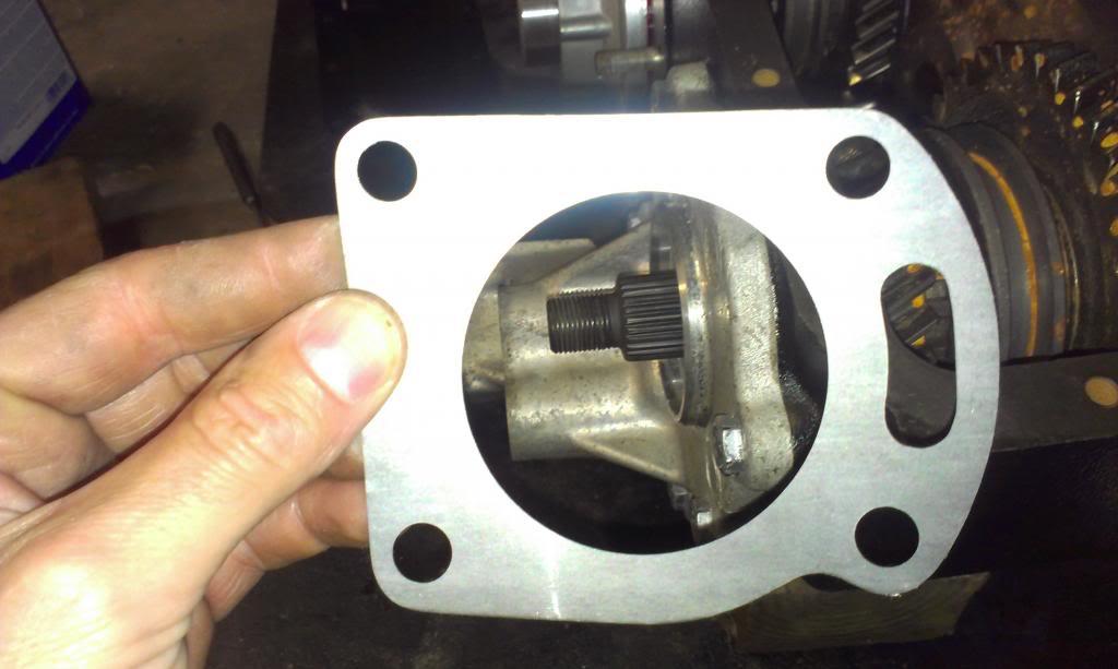
The pictures make this sealant look thick, and it does go on thick. But, when you bolt it all down, the excess will squeeze out. So, technically, by adding sealant, you are increasing the thickness of the shim stack by a little bit. Not much, but some. And since we are talking about .001's, a little is a lot. So, by removing the added thin shim (decreasing the overall end play), but then adding sealant (increasing the end play), it gets tricky. Basically, I want to start "tight" (around 0-.001" end play), then by adding sealant, get it a hair loose (.002-.003"). It takes a little trial and error, and the sealant does not set up instantly, so worse case scenario, you can pull it apart and play with the shims, if needed.

And after all of that, the assembled front output shaft end play is .001". This feels "good", and turns nice and smooth. I am happy with it.

IMAG0773_zpsd7108ff8-1.jpg


I still need to add the anaerobic sealant to seal the front plate to the case. Technically, this "could" increase the end play. But, that sealant is super thin, like razor thin once you bolt stuff together, so no worries.

But, before bolting the front down, I need to install the shift rails. I started to last night, and they kicked my butt, like usual.

That's it for now.

 
Back
Top